Takeuchi compact excavator TB125, TB135, TB145 / diesel TNE / diesel Yanmar. Service Manual - page 14
 

  Index      Manuals     Takeuchi compact excavator TB125 (12510003~), TB135 (13510004~), TB145 (14510004~) / diesel TNE / diesel Yanmar. Service Manual


Search            copyright infringement  


Content      ..     12      13      14      15     ..


Takeuchi compact excavator TB125, TB135, TB145 / diesel TNE / diesel Yanmar. Service Manual - page 14


III-144

TB125, 135, 145

System Operation

By law, all trucks have a heater/defroster as part of the standard equipment. When there
is a reason to add air conditioning, there are options to meet different needs. The available
space in the cab, operating environment, and owner preference can all play a part in the
type of AC unit selected. You will probably encounter roof-mounted and in-cab add on
systems, and even systems where the condenser is mounted on the roof and the
evaporator is attached to the back panel or mounted under the dash. In cooler climates
you may come across a cab with two heaters, the original and an auxiliary unit.

Air Conditioner—System Operation

We have described the movement of heat energy and basic HVAC system function in
Chapter 1. Now we will go into some detail on how an air conditioner operates. The
system is sealed to keep out air and moisture. To operate properly, the inside of the system
contains a measured amount of refrigerant and special refrigerant oil that keeps the
system lubricated. Figure 2-2 is an illustration of system components without the cab
outline, in-cab controls, component housing, and air ducts or vents. Please study it for
a moment. Note the information printed next to each component. Remember that the
components may be positioned and attached to the truck in various locations.

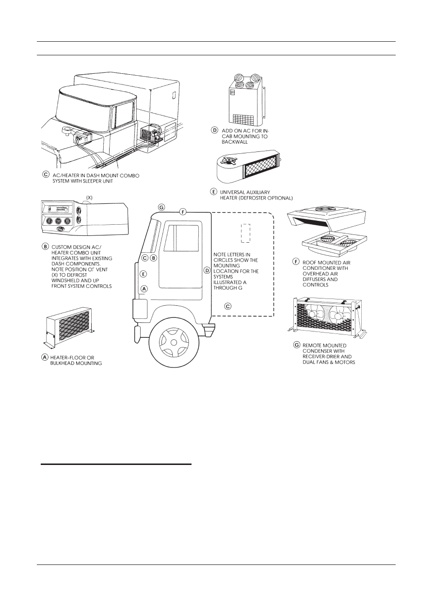
Figure 2-1

These illustrations show a
basic heater, HVAC system,
the combo system with
sleeper unit, add on AC roof
top and in cab units, roof
mounted condenser and
auxiliary units.

III-145

TB125, 135, 145

Air Conditioner—System Operation

The following AC components are discussed in detail in this section:

1.

Compressor/Clutch Assembly

2.

Condenser

3.

Receiver-Drier

4.

Expansion Valve

5.

Evaporator Coil

1. Compressor/Clutch Assembly

The compressor/clutch assembly is the heart of the system. When the clutch is
engaged, the compressor pumps refrigerant and oil around the system. It raises the
temperature and pressure of the refrigerant gas, and forces it to the condenser where
it changes state and becomes a liquid. The compressor also sucks the vaporized
refrigerant out of the evaporator and back inside itself in the form of gas. One way
valves inside the compressor separate the compressed gas (high pressure) side of the
system from the suction (low pressure) side. Figure 2-3 shows a cutaway view of a
compressor with the high and low pressure sides noted.

Figure 2-2

Air Conditioner components
are connected together to
illustrate system operation.
The components shown are
not to scale. The refrigerant
and refrigerant oil are clear
in color and not visible in
this drawing. The small
arrows inside the compo-
nents and connecting hoses
show the direction of
refrigerant flow (refrigerant
circuit).

III-146

TB125, 135, 145

System Operation

The clutch is mounted on the shaft of the compressor and is engaged by electromagnetic
action. Part of the clutch assembly is an electromagnetic wire coil. The coil is energized
through a thermostat that senses the temperature in the evaporator coil. If the evaporator
is too warm the electrical contacts close and allows power to flow to the clutch. The
compressor shaft is engaged and moves the refrigerant around inside the system. Figure
2-4 is a cutaway view of the clutch mounted on the compressor.

2. Condenser

The refrigerant gas leaves the compressor and moves through a high pressure hose to the
condenser. Inside the condenser the gas “changes state” and becomes a liquid. It is still
hot and under pressure. Remember in Chapter 1 when we talked about water at 212
degrees Fahrenheit? Heat energy was involved in the “change of state,” but the
temperature did not change. The same kind of action happens inside the AC system. The
refrigerant gas gives up a lot of heat energy to the outside air as it “changes state” in the
condenser. Figure 2-5 illustrates a condenser. Air moving through the condenser absorbs
heat from the refrigerant. The amount of air flow through the condenser is the major
factor in how well the condenser functions.

Figure 2-3

The compressor inlet is low
pressure and the outlet is
high pressure. The reed
valves are one way. They
open to allow refrigerant gas
to enter the compressor on
the down stroke and exit on
the upstroke. Note the open
valves in the illustrations.

Figure 2-4

The clutch shown here has
its electromagnetic coil
mounted on the compressor
body. When the coil is
energized, magnetic force
pulls the clutch drive plate
into the pulley. This action
locks the pulley to the
compressor drive shaft and
drives the compressor.

III-147

TB125, 135, 145

Air Conditioner—System Operation

3. Receiver-Drier

The liquid refrigerant continues to move inside the system, out of the condenser through
a tube or hose to the receiver-drier. The receiver-drier serves as a small storage tank and
filter for the refrigerant. It is also a good location to mount pressure switches and often
contains a sight glass (small window) used to view activity inside the system. The
receiver-drier, Figure 2-6, also separates gas (bubbles) from the liquid with a pick-up
tube as shown in this illustration. Some receiver-driers have a spring to preload the
desiccant pack.

Figure 2-5

As the refrigerant gas moves
through the tubing coil from
top to bottom, it condenses
(changes state) into a liquid.
For ease of installation,
condenser fittings are often
routed close together.

Figure 2-6

This cutaway view of a
receiver-drier shows the
filter elements, inlet, outlet
and refrigerant path. The
sight glass is a small
window into the system used
in diagnosis and when
adding refrigerant (charging
the system).

III-148

TB125, 135, 145

System Operation

4. Expansion Valve (Refrigerant Metering Device)

When refrigerant moves from the receiver-drier, it travels through another high pressure
hose to a metering device at the inlet of the evaporator coil. The metering device can be
an expansion valve, an expansion tube or a combination (multiple function) valve.
Between the compressor and this point inside the system, the pressure is high and can
range from 150 to 250 pounds per square inch. The expansion valve (TXV) is closely
connected to the evaporator. A diaphragm opens the valve by exerting pressure on the
spring. Pressure comes from gas inside the diaphragm housing on top of the valve and
in the sealed sensing bulb. The sensing tube is located in the outlet of the evaporator and
picks up heat from warm refrigerant leaving the evaporator. The gas in the valve
diaphragm housing and sensing tube expands when it gets warmer and forces the
expansion valve open at the metering orifice.

5. Evaporator Coil

The expansion valve or other type of metering device bleeds high pressure refrigerant
into the evaporator coil, where the pressure is low. The refrigerant expands rapidly in this
low pressure environment. When it expands it “changes state”. The sudden drop in
pressure brings the refrigerant temperature down quickly inside the evaporator coil.
Figure 2-8 shows an evaporator coil and thermostat. Refrigerant is sprayed into the
evaporator by the high side pressure when the expansion valve opens. The refrigerant
absorbs heat from the air when the blower forces the air through the fins. When the
thermostat probe senses the upper limit of the thermostat heat setting, a circuit closes.
The compressor clutch engages and the compressor operates and moves more refrigerant
to the high side of the system.

Figure 2-7

This block type expansion
valve cutaway view will
give you a better idea how
these valves work. Spring
pressure holds the valve
closed.

III-149

TB125, 135, 145

Air Conditioner—System Operation

Note:

Moisture in the air (humidity) condenses on the fins of the
evaporator as water droplets which drain out of the evaporator
through a drain hose. This action dehumidifies the air in the cab
as part of system operation, and contributes to operator comfort.

Cab air forced across the evaporator coil gives up heat energy to the cold
refrigerant inside the coil. The cooled air circulates in the cab for occupant
comfort. Refrigerant continues to expand and absorb heat energy in the
evaporator coil. Refrigerant changes from liquid to gas before it leaves the
evaporator on the way back to the compressor. The refrigerant gas moves to the
compressor through a low pressure (suction) hose. When the compressor is
operating, it sucks the refrigerant gas back inside, compressing and raising its
temperature and pressure.

Some of AC system operation is controlled by the operator, and some is automatic.
The operator can turn the system on and off, regulate the air velocity with the blower
control, and in some designs adjust the thermostat control. The system and compo-
nent operating range settings automatically cycle the clutch on and off. The operation
of the expansion valve or other refrigerant metering device at the inlet to the
evaporator is automatic.

Individual system features may differ, but the basic system function remains the

same. Variations in components and controls are described in Chapters 4 and 5. The
engine provides the power for both air conditioner and heater operation. It drives the
AC compressor and the cooling system water pump. Engine RPM affects the
efficiency of both the heater and air conditioner. The slower the engine RPM, the less
capacity a heater or AC system will have.

When an AC system is operating, the high pressure side
components, fittings and high pressure lines or hoses can be
hot enough to burn your skin if you touch them. This includes
the compressor, clutch, hoses, condenser, receiver-drier, and
any control devices or metal tubing. The low pressure side
will be cool to the touch. In operation the AC system is under
load and high side pressures normally range between 150 and
250 pounds per square inch for R-12 and higher for some
other refrigerants.

Figure 2-8

The evaporator coil as
shown is of fin and tube
construction. The thermostat
probe is positioned in
between the evaporator fins
and senses the temperature.

WARNING

III-150

TB125, 135, 145

Heater System Operation

Heater and air conditioner systems both have the same basic function of moving heat.
They take advantage of nature’s laws where heat energy always moves from a
warmer to a cooler area. In a heater system there is no “change of state” involved in
system operation. The system is sealed and operates under pressure, but the pressure
is low when compared to an air conditioner.

A heater system uses the engine coolant to carry excess heat energy to the cab air.

The heart of the system is the water pump. The water pump forces hot coolant through
a hose from the engine block and through the heater core. The coolant is returned to
the engine cooling system either at the suction side of the water pump or to the
radiator.

A control cable, attached to a water valve between the water pump and the heater

inlet, is used to control the flow of coolant to the heater. The heater fan or blower
forces cab air through the heater core where heat energy moves from the engine
coolant to the air in the cab. Figure 2-9 illustrates the main heater system compo-
nents. In-cab controls, component housing and air vents are not shown.

The following heater components are discussed in detail in this section:

1.

Heater Core

2.

Water Valves

3.

Defrosters and Ducts

4.

Blowers and Fans

Additional heater controls, ducts, air vents, blend-air doors, temperature regulating
devices and auxiliary heaters may be installed as part of a heater system. These may
be air, vacuum, electrical or mechanically operated.

System Operation

Figure 2-9

This view of a heater system
shows the main components
and how they are connected.

III-151

TB125, 135, 145

1. Heater Core

Heater cores are like small radiators. The fin and tube construction is designed
to route coolant flow for the best possible heat energy transfer from coolant to
cab air. Hoses from and to the engine are connected to the core with clamps. The
core outlet may be larger or the same size as the inlet.

2. Water Valves

Water valves may be cable, vacuum or air controlled. The valve can be either
open, closed or set part way open. Some valves have a bypass design to return
coolant to the engine. Most are manually controlled although electronic
systems are now being installed.

3. Defrosters and Ducts

Defrosting is accomplished by directing heated dry air through ducts to the
windshield. The heater system serves the dual purpose of defrosting and
heating. Controls are used to route the air flow to the windshield and occupant
areas by opening and closing duct doors. Controls may be manual, air or
vacuum.

Many vehicles use a “defrost interlock” system which utilizes the air

conditioner to dry the defrost air and clear the cab windows more quickly.

4. Blowers and Fans

Blowers or fans are used in the system to move cab air through the heater core
and evaporator. Air can be pushed or pulled through the core depending on
system design. Blower or fan speed is usually selected by the operator.

Environmental Effects on System Operation

The environment outside the cab involves more than the weather. It may be hot and
humid or cold and dry. That is only part of the condition the HVAC system must
handle to maintain an ideal comfort range. A truck can be at idle, in traffic or moving
along for hours on the Interstate at 65 M.P.H. The load condition on a trip can include
going out full, coming home empty, or driving across the Rockies or Kansas plains
during the day or night. The truck color and shape, the windows and angle of the sun
are all variables that can increase or decrease the “load” on the system. The following
are a few examples of environmental effect:

• A  black cab-over (COE) with a dark color interior will be more

difficult to cool than the same vehicle with white paint and a light
colored interior. The black cab picks up and holds the radiant heat
from the sun more easily than the white one.

• In Florida or Houston the humidity in mid summer can be very high

with the temperature in the high 90’s or low 100’s. The AC unit must
remove a lot of moisture from the air in the cab as the air moves
through the evaporator fins. The more moisture on the fins, the less
effective the transfer of heat is to the refrigerant inside the evaporator
coil.

Environmental Effects

III-152

TB125, 135, 145

• On a cold day the temperature can drop below zero. The engine may

run cooler so the engine coolant is cooler when it circulates through
the heater. The heat in the cab moves out of the cab faster (remember
heat always moves to a cooler area until both are the same tempera-
ture—nature’s law). To maintain cab comfort you have to increase the
flow of coolant through the heater, increase coolant temperature, and/
or move more air through the heater core.

• On a hot day, an off-road vehicle experiences cooling at a slower rate

than an on-road vehicle. This is a result of high sun-load, large window
area and often less insulation.

It is important for you to keep environmental effects in mind when you are servicing
or diagnosing heater or air conditioner systems. If you work in Denver the altitude will
affect system function and pressure. In Houston the heat and humidity may lower heat
transfer to the air at the condenser and increase system operating pressures.

Chapter Review

• HVAC systems range from simple cab heaters to multi-function

combination systems. The multi-function system can heat and cool
the cab and sleeper unit, and have separate auxiliary components and
controls for driver and passenger comfort.

• Both heater (engine) coolant and air conditioner refrigerant circulate

inside sealed, pressurized systems. The normal air conditioner oper-
ating pressure ranges from 150 to 250 pounds per square inch,
sometimes higher with a different refrigerant.

• Air conditioners have a high and a low pressure side within the system.

The compressor is the starting point of the high side. Pressure drops
at the expansion valve opening to the evaporator.

• The basic components of an AC system are the compressorclutch

assembly, high pressure lines, condenser, receiver-drier, expansion
valve, evaporator, thermostat, blower assembly, and suction lines.
There may be other controls installed for more complex systems.

• The basic components of a heater system are the inlet and outlet hoses,

a water valve and valve control, heater core and fan or blower
assembly. There may be other controls for more complex systems.

• An air conditioner system uses the “change of state” of refrigerant

inside the system to move heat from the cab air to the outside air.
Refrigerant changes from a gas to a liquid in the condenser, and back
to a gas in the evaporator.

• A heater system uses the heat from the engine, carried to the heater

core by the action of the water pump, to warm the air in the cab. There
is no change of state within the heater system.

• Environmental conditions affect how both heaters and air condition-

ers work. Weather, driving conditions, color of the vehicle are factors.
All contribute to heat gain or loss inside a cab and how much heat
energy must be moved to maintain occupant comfort.

System Operation

III-153

TB125, 135, 145

Inspection and Maintenance-
without gauges

• Discussion of Inspection & Maintenance Survey Results
• Visual Inspection - System Off
• Electrical System Inspection
• Performance Inspection - Engine Running
• Heater System Inspection
• Preventive Maintenance Worksheet
• Chapter Review

Discussion of Inspection & Maintenance Survey Results

There are three reasons for regular inspection and maintenance procedures:

1.

They save money in the long run by reducing down time and often
prevent more costly repairs.

2.

They help to insure driver comfort and safety.

3.

They add to your store of knowledge about these systems and maintain
your level of efficiency.

About half of all heavy duty vehicles have air conditioners. Surveys of AC system
owners find that over 30% of the systems are serviced every six months or less, and
another 62% are serviced at least once a year.

The survey also covered how often the different components required mainte-

nance. Figure 7.1 below shows survey finding percentages. Failure of any of the AC
components listed in the survey could cause a system to malfunction or stop cooling.

INSPECTION & MAINTENANCE SURVEY

Note:

The above survey results may not apply to your situation. Actual
operating conditions for the vehicles you service will determine
or influence maintenance frequency and requirements.

The following inspection procedures should take about 15 to 20 minutes, longer
if corrective steps, part replacement or adding refrigerant is necessary. There is a
“Preventive Maintenance Worksheet” you may use at the end of this chapter,
Figure 7-9

Click on any of these

subject headings to go

directly to the page

Figure 7-1

This chart shows mainte-
nance frequency, lists key
parts and how often they
require maintenance.

III-154

TB125, 135, 145

Visual Inspection - System Off

Your observations and the corrective measures you take may be different depending
on circumstances. The following inspection procedures are explained in more detail
below:

1.

Observe the System

2.

Inspect Parts

3.

Check Hoses and Fittings

4.

Check for Refrigerant Leaks

Use the following procedures as a general rule in performing a visual inspection with
the AC system off:

1. Observe the System

Your first inspection step is to answer the following question if you can:

Has the vehicle just come in off the road and has the HVAC system
been in use?

Did the operator or work order explain or describe any problems
about the system?

Did someone else work on the system yesterday, 700 miles down
the road? Your first inspection step is to answer these questions if
you can.

Even when someone has told you what is wrong with an
HVAC system, you should perform a visual inspection.
Always make a visual inspection before you hook up the
manifold gauge set. Never add refrigerant to a system until
you have made a complete visual and performance inspec-
tion.

2. Inspect Parts

Look at the system for what might come loose, leak, wear out or become dirty
and not function the way it should. The main points for visual inspection of the
system are emphasized in Figure 7-2.

Inspection & Maintenance

CAUTION

III-155

TB125, 135, 145

A. Condenser

 – Is it free of leaves, bugs, bird feathers or mud? The condenser

must be relatively clean to work well as a heat exchanger. How you clean the
condenser depends on where it is mounted. The condenser fin comb, air hose
and nozzle, or soap and water may be used. Where possible, check condenser
mounting bolts or screws and tighten them if necessary.

Condenser failure often results from loose hoses. Hose movement will cause

fatigue failure of condenser tubing adjacent to the fittings. Make sure the hoses
are securely clamped.

While inspecting the condenser check the receiver-drier sight glass and

connections. Look to see if the sight glass has a moisture indicator that is
showing moisture in the system.

B. Components Under the Hood

 – Tip the cab or raise the hood. Look at the

compressor mounting bracket, compressor clutch assembly, drive belt and
pulley alignment. The mounting bracket, compressor, clutch and drive pulley
should be fastened securely, and a clutch groove (there may be two groves)
should be in line with the drive pulley. Tighten all bolts shown in Figure 7-3,
as you inspect.

Visual Inspection

Figure 7-3

Engine and compressor
vibration can work mounting
bolts loose. Tighten all
mounting bolts as you
inspect the system. Slots in
the mounting bracket are
used to move the compres-
sor clutch assembly in order
to adjust belt tension or
alignment.

Figure 7-2

This system illustration
notes the main points for
visual inspection.

III-156

TB125, 135, 145

C. Drive Belt

 – The drive belt should be tight and in good condition. Use a belt

tension gauge to check tension (120 pounds maximum). With experience, you
can feel belt tension by twisting the belt. Try feeling belt tension after using the
gauge, when you know the tension is correct. Replace belts if they are frayed
or look worn.

If the clutch pulley/belt alignment is obviously off, you need to loosen the

compressor or mounting bracket, or both—and use the alignment bar to line up
the clutch pulley with the drive pulley. Tighten compressor mounting bolts
first, then the bolts holding the bracket. The mounting bracket should have slots
or other means of adjustment to allow you to adjust the tension of the drive belt.
When you use a pry bar to apply tension, be sure you do not pry against the
compressor. Pry against the mounting bracket.

3. Check Hoses and Fittings

Check all hoses and fittings. Look for places where hoses flex when the cab is tilted.
Any places the hoses or fittings are fastened, clamped, connected, bent or secured are
potential wear points. This also applies to places where hoses are not clamped or
supported but should be (often near the condenser). All of these spots are potential
leak or damage points. Tighten, re-fasten, add, or replace as indicated by your
inspection.

4. Check for Refrigerant Leaks

System refrigerant leaks can be anywhere but there are obvious places. You can spot
some by looking for signs of refrigerant oil forced out with refrigerant leakage. One
location leaks frequently occur is the compressor shaft seal. The shaft and seal are
hidden behind the clutch assembly, but centrifugal force will throw the oil off the
shaft and against the engine, bracket or whatever is close. Check these points when
you examine the compressor clutch and mounting bracket. A solution of soap and
water applied around potential leak points works well for detecting leaks. A leak in
the evaporator may be indicated if you feel around the condensate drain hole and find
oil present.

Note:

You can add inexpensive dry nitrogen gas to the system instead of R-
12 if system pressures are low. Dispense the gas at no more than 200-
250 PSI as this is sufficient pressure to cause or indicate a leak point
in the AC system. AC service procedures for complete system
recovering of refrigerant, evacuating, and recharging are covered
and illustrated in 

Chapter 9.

Note:

A leaking heater core could also result in coolant at the condensate
drain.

Inspection & Maintenance

III-157

TB125, 135, 145

You can feel for oil at the bottom of all connections (see Figure 7-4) if the
system is not too hot. Of course, a few minutes with an electronic leak detector
is the best way to check for leaks. Keep in mind that pressure is different in a
system at rest, so small leaks may be hard to find. Pressure in a system at rest,
will equalize at from 60 to 95 PSI, depending on outside air temperature. This
means there is more pressure in the low side of the system at rest than during
normal system operation. Just the opposite is true of the high side; at rest, high
side pressure is lower. You may want to use the detector to check for leaks in
the high side when the air conditioner is operating, if you suspect a leak and
can’t find it when the system is at rest.

Electrical System Inspection

The two stages of an electrical inspection are explained in more detail below:

1.

Inspect Electrical Connections

2.

Check Electrical Current Flow and Device Functions

Use the following procedures to perform an electrical system inspection:

1. Inspect Electrical Connections

First, while you are making your visual inspection under the hood (cab) and/or
at the roof top condenser, take a moment and check all electrical connections
visually and by feel. Look for any corrosion on leads or connectors and clean
them. Make sure all leads and wires are properly supported and securely
connected.

2. Check Electrical Current Flow and Device Functions

Perform the following steps to check current flow and electrical device
functions:

A. Turn the Ignition On

 – To check current flow the ignition must be on.

Electrical System Inspection

Figure 7-4

This illustration shows a
potential refrigerant leak
point at the condenser
fitting.

III-158

TB125, 135, 145

B. Turn the AC System On 

– This will power the thermostat and clutch.

If it does not come on, use the AC mode switch to check the leads to the
switch. You should be able to hear a “click” from the thermostat and hear
the clutch drive plate “snap” against the clutch pulley. You can not check
thermostat cycling on and off until you do the performance inspection.
Figure 7-5 illustrates a typical AC electrical system and the places you
should inspect.

C. Check Fuses

  – If there is a failure and you have made sure all

connections are clean and tight, you need to check fuses—in-cab as well
as in-line.

D. Check Clutch Engagement

 – Since you can’t see and may not hear the

clutch engage, get out and look at the clutch. If it’s engaged, you will see
that the drive plate is against the pulley and not slightly spaced from it. If
you are not sure the clutch is engaged, look for the lead wire connector near
the clutch. Break and close that connection. The clutch will disengage and
engage again.

E. Test Blower Speed Operation

 – Some systems have a common switch

that turns on the air conditioner and powers the blower motor. Test blower
speed operation by adjusting this or the separate blower control switch.
Feeling the air flow from the ducts or note blower sound (speed) changes.

F. Inspect Roof Mounted Condensers

 – Don’t forget to inspect roof

mounted condensers and AC systems for dirt and debris. Be sure the
condenser fan(s) are working properly and all parts and electrical connec-
tions are securely fastened. The roof mounted condenser fans may come
on when the system is turned on. Like the thermostat and most clutches,
the normal on-off cycling action can not be observed until the engine is
running with the AC system on.

Inspection & Maintenance

Figure 7-5

The electrical system
inspection points are noted
with check marks (

) on

this wiring diagram
(electrical schematic).

III-159

TB125, 135, 145

Performance Inspection – Engine Running

The purpose of visual and electrical inspection is to detect obvious problems and
assure AC system function for an accurate performance inspection. If you do the
performance inspection first, you could be mislead. Problem areas discovered during
the performance inspection can give you false clues or symptoms, and result in repair
errors and come-backs. The following performance inspection procedures are
explained in more detail below:

1.

Inspect System Component Cycling and

Cab Temperature Levels

2.

Check Clutch Cycling Under Load

3.

Check Sight Glass

The performance inspection does not cover pressure and temperature sensitive
safety devices (cutout switches, fan control, Trinary etc.). Testing these devices
requires the use of the manifold gauge set for observation of internal system
pressures during tests. These are explained in 

Chapter 8.

Use the following procedures as a general rule in a performance inspection:

1. Inspect System Component Cycling and Cab

Temperature Levels

A. Turn On the Engine and Air Conditioner

  – Inspect for system

component cycling and cab temperature levels.

Note:

System performance testing will be much faster if all doors
and windows in the cab are closed.

The cab air must cool down to thermostat control setting levels
before system components will cycle on and off, indicating
correct function. This is called ‘stabilizing the system’ and takes
about five minutes of operation. In very hot weather the system
may not cycle.

B. Check Thermometer Readings

  – In the cab you can use your

thermometer to measure air temperature at the vents. When the evaporator
is easy to reach with a thermometer probe without removing some of the
dash or duct work, use the probe to measure evaporator temperature.
When the AC unit is on and working correctly, you can see the thermom-
eter dial needle move down to about 32 degrees, then rise six to ten degrees
and move back down again. The movement up and down indicates that the
cycling clutch and thermostat, or orifice tube and accumulator pressure
switch (to the clutch) are functioning correctly. In systems with a non-
cycling clutch, this movement indicates correct function of the refrigerant
metering device.

The needle movement is called “temperature swing.” When you can

adjust the thermostat setting, the range of swing should change. For
example, from full cooling (cold) to moderate (between cold and warm),
the swing may change from 32-38 to 32-42 degrees.

Electrical System Inspection


Content      ..     12      13      14      15     ..