Physics For Scientists And Engineers 6E - part 307
 

  Index      Production     Physics For Scientists And Engineers 6E


Search            


Content   ..  305  306  307  308   ..


Physics For Scientists And Engineers 6E - part 307


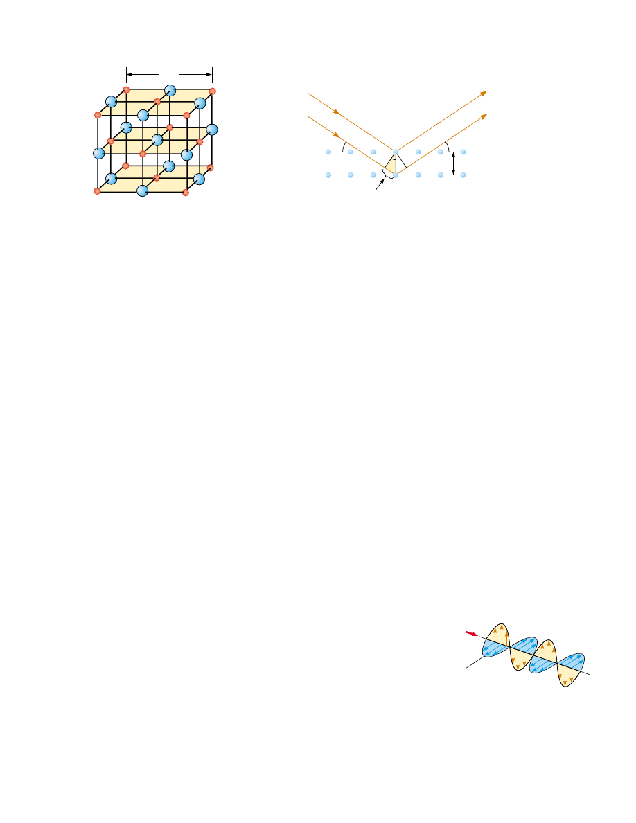
the beam reflected from the lower plane travels farther than the beam reflected from
the upper plane. The effective path difference is 2sin !. The two beams reinforce
each  other  (constructive  interference)  when  this  path  difference  equals  some
integer  multiple  of  %.  The  same  is  true  for  reflection  from  the  entire  family  of
parallel  planes.  Hence,  the  condition  for  constructive interference  (maxima  in  the
reflected beam) is

(38.13)

This  condition  is  known  as 

Bragg’s  law, after  W.  L.  Bragg  (1890–1971),  who  first

derived the relationship. If the wavelength and diffraction angle are measured, Equa-
tion 38.13 can be used to calculate the spacing between atomic planes.

38.6 Polarization of Light Waves

In  Chapter  34  we  described  the  transverse  nature  of  light  and  all  other  electromag-
netic  waves.  Polarization,  discussed  in  this  section,  is  firm  evidence  of  this  transverse
nature.

An ordinary beam of light consists of a large number of waves emitted by the atoms

of  the  light  source.  Each  atom  produces  a  wave  having  some  particular  orientation
of the electric field vector 

E, corresponding to the direction of atomic vibration. The

direction of polarization of each individual wave is defined to be the direction in which
the electric field is vibrating. In Figure 38.28, this direction happens to lie along the y
axis.  However,  an  individual  electromagnetic  wave  could  have  its 

E vector  in  the  yz

plane,  making  any  possible  angle  with  the  axis.  Because  all  directions  of  vibration
from a wave source are possible, the resultant electromagnetic wave is a superposition
of  waves  vibrating  in  many  different  directions.  The  result  is  an 

unpolarized light

beam, represented in Figure 38.29a. The direction of wave propagation in this figure is
perpendicular  to  the  page.  The  arrows  show  a  few  possible  directions  of  the  electric
field vectors for the individual waves making up the resultant beam. At any given point
and at some instant of time, all these individual electric field vectors add to give one re-
sultant electric field vector.

As  noted  in  Section  34.2,  a  wave  is  said  to  be 

linearly  polarized if  the  resultant

electric field 

E vibrates in the same direction at all times at a particular point, as shown

in  Figure  38.29b.  (Sometimes,  such  a  wave  is  described  as  plane-polarized, or  simply
polarized.) The plane formed by 

E and the direction of propagation is called the plane

" 1, 2, 3,

  $  $  $

2d sin ! " m


%

S E C T I O N   3 8 . 6 •  Polarizaion of Light Waves

1225

Bragg’s law

a

Figure 38.26 Crystalline structure of

sodium chloride (NaCl). The blue spheres

represent Cl

'

ions, and the red spheres

represent Na

,

ions. The length of the cube

edge is " 0.562 737 nm.

PITFALL PREVENTION 

38.4 Different Angles

Notice  in  Figure  38.27  that  the
angle  ! is  measured  from  the
reflecting  surface,  rather  than
from the normal, as in the case of
the  law  of  reflection  in  Chapter
35.  With  slits  and  diffraction
gratings,  we  also  measured  the
angle  ! from  the  normal  to  the
array of slits. Because of historical
tradition,  the  angle  is  measured
differently  in  Bragg  diffraction,
so  interpret  Equation  38.13  with
care.

θ

Incident

beam

Reflected

beam

Upper plane

Lower plane

d

θ

θ

sin

θ

Figure 38.27 A two-dimensional description of the

reflection of an x-ray beam from two parallel crystalline

planes separated by a distance d. The beam reflected from

the lower plane travels farther than the one reflected from

the upper plane by a distance 2sin 

!

.

z

y

E

c

B

x

Figure 38.28 Schematic diagram

of an electromagnetic wave

propagating at velocity 

c in the x

direction. The electric field vibrates

in the xy plane, and the magnetic

field vibrates in the xz plane.

of  polarization  of  the  wave.  If  the  wave  in  Figure  38.28  represents  the  resultant  of  all
individual waves, the plane of polarization is the xy plane.

It  is  possible  to  obtain  a  linearly  polarized  beam  from  an  unpolarized  beam  by

removing all waves from the beam except those whose electric field vectors oscillate in
a single plane. We now discuss four processes for producing polarized light from unpo-
larized light.

Polarization by Selective Absorption

The  most  common  technique  for  producing  polarized  light  is  to  use  a  material  that
transmits  waves  whose  electric  fields  vibrate  in  a  plane  parallel  to  a  certain  direction
and that absorbs waves whose electric fields vibrate in all other directions.

In  1938,  E.  H.  Land  (1909–1991)  discovered  a  material,  which  he  called  polaroid,

that polarizes light through selective absorption by oriented molecules. This material is
fabricated in thin sheets of long-chain hydrocarbons. The sheets are stretched during
manufacture so that the long-chain molecules align. After a sheet is dipped into a solu-
tion  containing  iodine,  the  molecules  become  good  electrical  conductors.  However,
conduction takes place primarily along the hydrocarbon chains because electrons can
move easily only along the chains. As a result, the molecules readily absorb light whose
electric  field  vector  is  parallel  to  their  length  and  allow  light  through  whose  electric
field vector is perpendicular to their length.

It is common to refer to the direction perpendicular to the molecular chains as

the  transmission  axis. In an ideal polarizer,  all  light with 

E parallel to the transmis-

sion axis is transmitted, and all light with 

E perpendicular to the transmission axis is

absorbed.

Figure 38.30 represents an unpolarized light beam incident on a first polarizing

sheet,  called  the  polarizer. Because  the  transmission  axis  is  oriented  vertically  in
the figure, the light transmitted through this sheet is polarized vertically. A second
polarizing  sheet,  called  the  analyzer, intercepts  the  beam.  In  Figure  38.30,  the
analyzer  transmission  axis  is  set  at  an  angle  ! to  the  polarizer  axis.  We  call  the
electric field vector of the first transmitted beam 

E

0

. The component of 

E

0

perpen-

dicular to the analyzer axis is completely absorbed. The component of 

E

0

parallel to

the  analyzer  axis,  which  is  allowed  through  by  the  analyzer,  is E

0

cos!.  Because

the intensity  of  the  transmitted  beam  varies  as  the  square  of  its  magnitude,  we
conclude  that  the  intensity  of  the  (polarized)  beam  transmitted  through  the
analyzer varies as

(38.14)

I


max

 cos

2

 !

1226

C H A P T E R   3 8 •  Diffraction Patterns and Polarization

E

(a)

E

(b)

Figure 38.29 (a) A representation

of an unpolarized light beam viewed

along the direction of propagation

(perpendicular to the page). The

transverse electric field can vibrate

in any direction in the plane of

the page with equal probability.

(b) A linearly polarized light beam

with the electric field vibrating in

the vertical direction.

Analyzer

Unpolarized

light

Transmission

axis

Polarized

light

E

0


cos

E

0

Polarizer

θ

θ

Active Figure 38.30 Two polarizing sheets whose transmission axes make an angle 

!

with each other. Only a fraction of the polarized light incident on the analyzer is trans-

mitted through it.

Rotate the analyzer at 

the Active Figures link at

http://www.pse6.com, to see the

effect on the transmitted light.

Malus’s law

where  I

max

is  the  intensity  of  the  polarized  beam  incident  on  the  analyzer.  This

expression,  known  as 

Malus’s  law,

2

applies  to  any  two  polarizing  materials

whose transmission  axes  are  at  an  angle  ! to  each  other.  From  this  expression,  we
see  that  the  intensity  of  the  transmitted  beam  is  maximum  when  the  transmission
axes  are  parallel  (! " 0  or  180°)  and  that  it  is  zero  (complete  absorption  by  the
analyzer)  when  the  transmission  axes  are  perpendicular  to  each  other.  This
variation in transmitted intensity through a pair of polarizing sheets is illustrated in
Figure 38.31.

Polarization by Reflection

When an unpolarized light beam is reflected from a surface, the reflected light may be
completely  polarized,  partially  polarized,  or  unpolarized,  depending  on  the  angle  of
incidence. If the angle of incidence is 0°, the reflected beam is unpolarized. For other
angles of incidence, the reflected light is polarized to some extent, and for one partic-
ular angle of incidence, the reflected light is completely polarized. Let us now investi-
gate reflection at that special angle.

Suppose  that  an  unpolarized  light  beam  is  incident  on  a  surface,  as  in  Figure

38.32a. Each individual electric field vector can be resolved into two components: one
parallel to the surface (and perpendicular to the page in Fig. 38.32, represented by the
dots), and the other (represented by the brown arrows) perpendicular both to the first
component and to the direction of propagation. Thus, the polarization of the entire
beam can be described by two electric field components in these directions. It is found
that  the  parallel  component  reflects  more  strongly  than  the  perpendicular  compo-
nent,  and  this  results  in  a  partially  polarized  reflected  beam.  Furthermore,  the
refracted beam is also partially polarized.

Now suppose that the angle of incidence !

1

is varied until the angle between the

reflected  and  refracted  beams  is  90°,  as  in  Figure  38.32b.  At  this  particular  angle
of incidence,  the  reflected  beam  is  completely  polarized  (with  its  electric  field
vector  parallel  to  the  surface),  and  the  refracted  beam  is  still  only  partially
polarized.  The  angle  of  incidence  at  which  this  polarization  occurs  is  called  the
polarizing angle !

p

.

S E C T I O N   3 8 . 6 •  Polarizaion of Light Waves

1227

2

Named  after  its  discoverer,  E.  L.  Malus  (1775–1812).  Malus  discovered  that  reflected  light  was

polarized by viewing it through a calcite (CaCO

3

) crystal.

Figure 38.31 The intensity of light transmitted through two polarizers depends on the

relative orientation of their transmission axes. (a) The transmitted light has maximum

intensity when the transmission axes are aligned with each other. (b) The transmitted

light has lesser intensity when the transmission axes are at an angle of 451 with each

other. (c) The transmitted light intensity is a minimum when the transmission axes are

perpendicular to each other.

Henry Leap and Jim Lehman

(a)

(b)

(c)

We can obtain an expression relating the polarizing angle to the index of refrac-

tion of the reflecting substance by using Figure 38.32b. From this figure, we see that
!

p

,

90° , !

2

"

180°;  thus  !

2

"

90° ' !

p

Using  Snell’s  law  of  refraction  (Eq.  35.8)

and taking n

1

"

1.00 for air and n

2

"

n, we have

Because  sin!

2

"

sin(90° ' !

p

) " cos!

p

,  we  can  write  this  expression  for  as 

" sin!

p

/cos!

p

, which means that

(38.15)

This  expression  is  called 

Brewster’s  law, and  the  polarizing  angle  !

p

is  sometimes

called 

Brewster’s angle, after its discoverer, David Brewster (1781–1868). Because n

varies  with  wavelength  for  a  given  substance,  Brewster’s  angle  is  also  a  function  of
wavelength.

We  can  understand  polarization  by  reflection  by  imagining  that  the  electric  field

in the incident light sets electrons at the surface of the material in Figure 38.32b into
oscillation.  The  component  directions  of  oscillation  are  (1)  parallel  to  the  arrows
shown on the refracted beam of light and (2) perpendicular to the page. The oscillat-
ing  electrons  act  as  antennas  radiating  light  with  a  polarization  parallel  to  the  direc-
tion of  oscillation.  For  the  oscillations  in  direction  (1),  there  is  no  radiation  in  the
perpendicular  direction,  which  is  along  the  reflected  ray  (see  the  ! " 90° direction
in Figure  34.11).  For  oscillations  in  direction  (2),  the  electrons  radiate  light  with  a
polarization perpendicular to the page (the ! " 0 direction in Figure 34.11). Thus, the
light  reflected  from  the  surface  at  this  angle  is  completely  polarized  parallel  to  the
surface.

Polarization  by  reflection  is  a  common  phenomenon.  Sunlight  reflected  from

water,  glass,  and  snow  is  partially  polarized.  If  the  surface  is  horizontal,  the  electric

" tan!

p

"

sin!

1

sin!


2

"

sin!

p

sin!


2

1228

C H A P T E R   3 8 •  Diffraction Patterns and Polarization

1

θ

Refracted

beam

Refracted

beam

(a)

(b)

n

1

Incident

beam

Reflected

beam

n

2

90

°

Incident

beam

Reflected

beam

n

1

n

2

1

θ

2

θ

p

θ

p

θ

2

θ

Figure 38.32 (a) When unpolarized light is incident on a reflecting surface, the

reflected and refracted beams are partially polarized. (b) The reflected beam is

completely polarized when the angle of incidence equals the polarizing angle 

!

p

, which

satisfies the equation " tan

!

p

. At this incident angle, the reflected and refracted rays

are perpendicular to each other.

Brewster’s law


Content   ..  305  306  307  308   ..