Physics For Scientists And Engineers 6E - part 299
 

  Index      Production     Physics For Scientists And Engineers 6E


Search            


Content   ..  297  298  299  300   ..


Physics For Scientists And Engineers 6E - part 299


S E C T I O N   37. 6 •  Interference in Thin Films

1193

A thin, wedge-shaped film of index of refraction is illumi-
nated  with  monochromatic  light  of  wavelength  &,  as  illus-
trated  in  Figure  37.21a.  Describe  the  interference  pattern
observed for this case.

Solution The interference pattern, because it is created by
a thin film of variable thickness surrounded by air, is a series
of alternating bright and dark parallel fringes. A dark fringe
corresponding  to  destructive  interference  appears  at  point
O, the apex, because here the upper reflected ray undergoes
a  180° phase  change  while  the  lower  one  undergoes  no
phase change.

According to Equation 37.17, other dark minima appear

when 2nt m&; thus, t

1

#

&

/2nt

2

#

&

/nt

3

#

3&/2n, and

so  on.  Similarly,  the  bright  maxima  appear  at  locations 
where  satisfies  Equation  37.16, 

,  cor-

responding to thicknesses of &/4n, 3&/4n, 5&/4n, and so on.

If  white  light  is  used,  bands  of  different  colors  are

observed at different points, corresponding to the different
wavelengths  of  light  (see  Fig.  37.21b).  This  is  why  we  see
different  colors  in  soap  bubbles  and  other  films  of  varying
thickness.

2nt # ((

1

2

)&

Example 37.5 Interference in a Wedge-Shaped Film

Si

180

° phase

change

1

2

SiO

Air

= 3.5

= 1.45

= 1

180

° phase

change

(a)

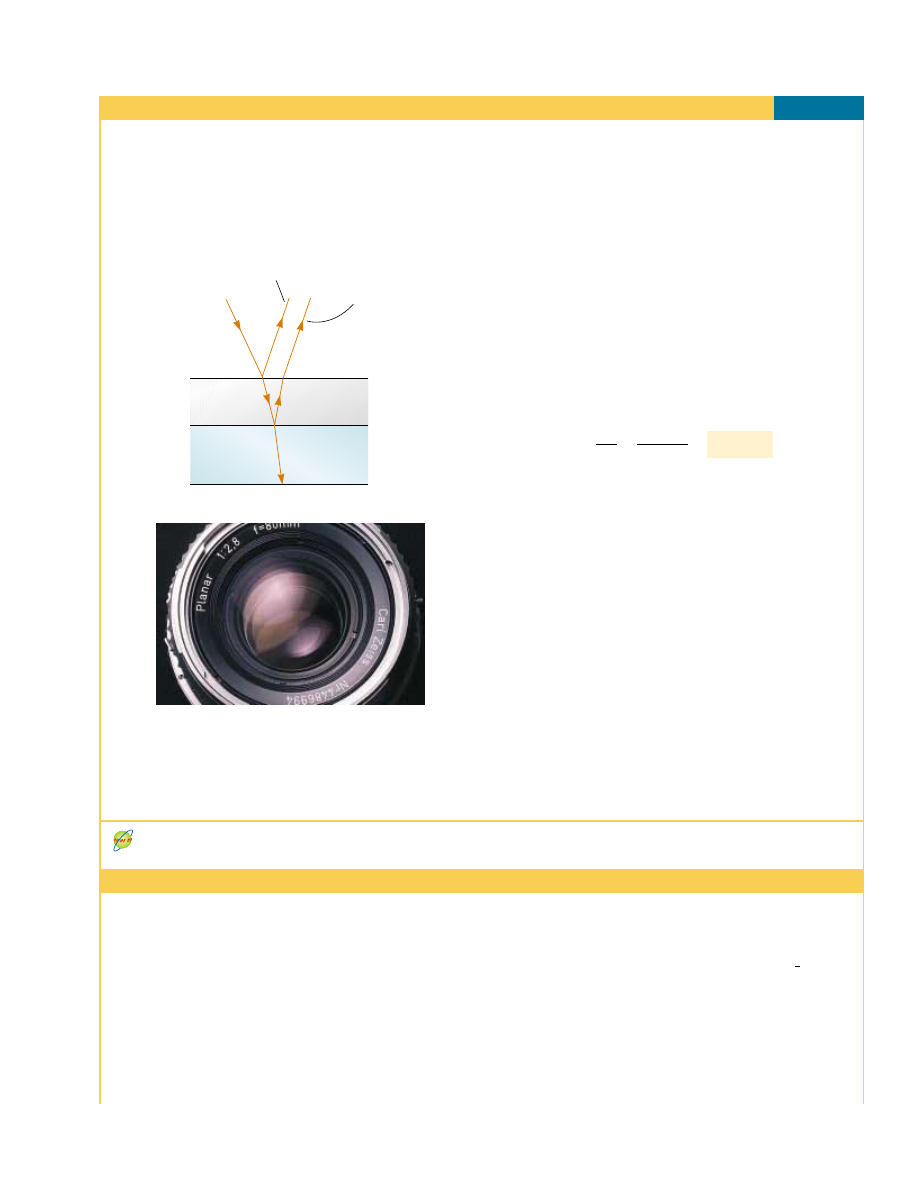
Figure 37.20 (Example 37.4) (a) Reflective losses from a

silicon solar cell are minimized by coating the surface of the

cell with a thin film of silicon monoxide. (b) The reflected

light from a coated camera lens often has a reddish-violet

appearance.

Kristen Brochmann/Fundamental Photographs

Investigate the interference for various film properties at the Interactive Worked Example link at http://www.pse6.com.

Example 37.4 Nonreflective Coatings for Solar Cells

Interactive

Solar cells—devices that generate electricity when exposed to
sunlight—are  often  coated  with  a  transparent,  thin  film  of
silicon monoxide (SiO, # 1.45) to minimize reflective losses
from the surface. Suppose that a silicon solar cell (# 3.5) is
coated with a thin film of silicon monoxide for this purpose
(Fig.  37.20).  Determine  the  minimum  film thickness  that

produces the least reflection at a wavelength of 550 nm, near
the center of the visible spectrum.

Solution Figure 37.20a helps us conceptualize the path of
the  rays  in  the  SiO  film  that  result  in  interference  in  the
reflected  light.  Based  on  the  geometry  of  the  SiO  layer,
we categorize  this  as  a  thin-film  interference  problem.  To
analyze  the  problem,  note  that  the  reflected  light  is  a
minimum when rays 1 and 2 in Figure 37.20a meet the con-
dition of destructive interference. In this situation, both rays
undergo a 180° phase change upon reflection—ray 1 from
the upper SiO surface and ray 2 from the lower SiO surface.
The net change in phase due to reflection is therefore zero,
and the condition for a reflection minimum requires a path
difference of &

n

/2, where &

n

is the wavelength of the light in

SiO. Hence 2# &/2n, where & is the wavelength in air and
is the index of refraction of SiO. The required thickness is

To finalize the problem, we can investigate the losses in

typical solar cells. A typical uncoated solar cell has reflective
losses as high as 30%; a SiO coating can reduce this value to
about  10%.  This  significant  decrease  in  reflective  losses
increases  the  cell’s  efficiency  because  less  reflection  means
that  more  sunlight  enters  the  silicon  to  create  charge
carriers  in  the  cell.  No  coating  can  ever  be  made  perfectly
nonreflecting because the required thickness is wavelength-
dependent  and  the  incident  light  covers  a  wide  range  of
wavelengths.

Glass lenses used in cameras and other optical instru-

ments  are  usually  coated  with  a  transparent  thin  film  to
reduce or eliminate unwanted reflection and enhance the
transmission of light through the lenses. The camera lens
in  Figure  37.20b  has  several  coatings  (of  different  thick-
nesses) to minimize reflection of light waves having wave-
lengths  near  the  center  of  the  visible  spectrum.  As  a
result,  the  little  light  that  is  reflected  by  the  lens  has  a
greater  proportion  of  the  far  ends  of  the  spectrum  and
often appears reddish-violet.

94.8 nm

#

&

4n

#

550 nm

4(1.45)

#

(b)

1194

C H A P T E R   37 •  Interference of Light Waves

t

1

O

t

2

t

3

Incident

light

(a)

n

Figure 37.21 (Example 37.5) (a) Inter-

ference bands in reflected light can be

observed by illuminating a wedge-

shaped film with monochromatic light.

The darker areas correspond to regions

where rays tend to cancel each other

because of interference effects. (b) Inter-

ference in a vertical film of variable

thickness. The top of the film appears

darkest where the film is thinnest.

Active Figure 37.22 Diagram of

the Michelson interferometer. A

single ray of light is split into two

rays by mirror M

0

, which is called a

beam splitter. The path difference

between the two rays is varied with

the adjustable mirror M

1

. As M

1

is

moved, an interference pattern

changes in the field of view.

At the Active Figures link at

http://www.pse6.com, move

the mirror to see the effect

on the interference pattern and

use the interferometer to

measure the wavelength of light.

Richard Megna/Fundamental Photographs 

37.7 The Michelson Interferometer

The 

interferometer, invented  by  the  American  physicist  A.  A.  Michelson

(1852–1931),  splits  a  light  beam  into  two  parts  and  then  recombines  the  parts  to
form  an  interference  pattern.  The  device  can  be  used  to  measure  wavelengths  or
other lengths with great precision because a large and precisely measurable displace-
ment of one of the mirrors is related to an exactly countable number of wavelengths
of light.

A  schematic  diagram  of  the  interferometer  is  shown  in  Figure  37.22.  A  ray

of light  from  a  monochromatic  source  is  split  into  two  rays  by  mirror  M

0

,  which

is inclined  at  45° to  the  incident  light  beam.  Mirror  M

0

,  called  a  beam  splitter,

transmits  half  the  light  incident  on  it  and  reflects  the  rest.  One  ray  is  reflected
from M

0

vertically  upward  toward  mirror  M

1

,  and  the  second  ray  is  transmitted

horizontally  through  M

0

toward  mirror  M

2

.  Hence,  the  two  rays  travel  separate

paths  L

1

and  L

2

.  After  reflecting  from  M

1

and  M

2

,  the  two  rays  eventually

recombine at M

0

to produce an interference pattern, which can be viewed through

a telescope.

The interference condition for the two rays is determined by their path length dif-

ferences. When the two mirrors are exactly perpendicular to each other, the interfer-
ence pattern is a target pattern of bright and dark circular fringes, similar to Newton’s
rings.  As  M

1

is  moved,  the  fringe  pattern  collapses  or  expands,  depending  on  the

direction in which M

1

is moved. For example, if a dark circle appears at the center of

the target pattern (corresponding to destructive interference) and M

1

is then moved a

distance &/4 toward M

0

, the path difference changes by &/2. What was a dark circle at

the  center  now  becomes  a  bright  circle.  As  M

1

is  moved  an  additional  distance  &/4

toward  M

0

,  the  bright  circle  becomes  a  dark  circle  again.  Thus,  the  fringe  pattern

shifts by one-half fringe each time M

1

is moved a distance &/4. The wavelength of light

is then measured by counting the number of fringe shifts for a given displacement of
M

1

. If the wavelength is accurately known, mirror displacements can be measured to

within a fraction of the wavelength.

We  will  see  an  important  historical  use  of  the  Michelson  interferometer  in  our

discussion  of  relativity  in  Chapter  39.  Modern  uses  include  the  following  two
applications.

Telescope

M

1

M

2

M

0

L

2

L

1

Light

source

(b)

S E C T I O N   37. 7 •  The Michelson Interferometer

1195

Fourier Transform Infrared Spectroscopy (FTIR)

Spectroscopy is the study of the wavelength distribution of radiation from a sample
that can be used to identify the characteristics of atoms or molecules in the sample.
Infrared  spectroscopy  is  particularly  important  to  organic  chemists  in  analyzing
organic molecules. Traditional spectroscopy involves the use of an optical element,
such as a prism (Section 35.7) or a diffraction grating (Section 38.4), which spreads
out various wavelengths in a complex optical signal from the sample into different
angles. In this way, the various wavelengths of radiation and their intensities in the
signal can be determined. These types of devices are limited in their resolution and
effectiveness because they must be scanned through the various angular deviations
of the radiation.

The  technique  of  Fourier  Transform  Infrared  Spectroscopy (FTIR)  is  used  to  create  a

higher-resolution  spectrum  in  a  time  interval  of  one  second  that  may  have  required
30 minutes with a standard spectrometer. In this technique, the radiation from a sam-
ple enters a Michelson interferometer. The movable mirror is swept through the zero-
path-difference  condition  and  the  intensity  of  radiation  at  the  viewing  position  is
recorded.  The  result  is  a  complex  set  of  data  relating  light  intensity  as  a  function  of
mirror position, called an interferogram. Because there is a relationship between mirror
position  and  light  intensity  for  a  given  wavelength,  the  interferogram  contains  infor-
mation about all wavelengths in the signal.

In  Section  18.8,  we  discussed  Fourier  analysis  of  a  waveform.  The  waveform  is  a

function that contains information about all of the individual frequency components
that  make  up  the  waveform.

3

Equation  18.16  shows  how  the  waveform  is  generated

from  the  individual  frequency  components.  Similarily,  the  interferogram  can  be
analyzed  by  computer,  in  a  process  called  a  Fourier  transform,  to  provide  all  of  the
wavelength  components.  This  is  the  same  information  generated  by  traditional
spectroscopy, but the resolution of FTIR is much higher.

Laser Interferometer Gravitational-Wave Observatory (LIGO)

Einstein’s general theory of relativity (Section 39.10) predicts the existence of gravi-
tational waves
. These waves propagate from the site of any gravitational disturbance,
which  could  be  periodic  and  predictable,  such  as  the  rotation  of  a  double  star
around  a  center  of  mass,  or  unpredictable,  such  as  the  supernova  explosion  of  a
massive star.

In Einstein’s theory, gravitation is equivalent to a distortion of space. Thus, a gravi-

tational disturbance causes an additional distortion that propagates through space in a
manner  similar  to  mechanical  or  electromagnetic  waves.  When  gravitational  waves
from  a  disturbance  pass  by  the  Earth,  they  create  a  distortion  of  the  local  space.
The LIGO  apparatus  is  designed  to  detect  this  distortion.  The  apparatus  employs  a
Michelson interferometer that uses laser beams with an effective path length of several
kilometers.  At  the  end  of  an  arm  of  the  interferometer,  a  mirror  is  mounted  on  a
massive  pendulum.  When  a  gravitational  wave  passes  by,  the  pendulum  and  the
attached mirror move, and the interference pattern due to the laser beams from the
two arms changes.

Two sites have been developed in the United States for interferometers in order to

allow  coincidence  studies  of  gravitational  waves.  These  sites  are  located  in  Richland,
Washington, and Livingston, Louisiana. Figure 37.23 shows the Washington site. The
two arms of the Michelson interferometer are evident in the photograph. Test runs are
being performed as of the printing of this book. Cooperation with other gravitational
wave  detectors,  such  as  VIRGO  in  Cascina,  Italy,  will  allow  detailed  studies  of
gravitational waves.

3

In  acoustics,  it  is  common  to  talk  about  the  components  of  a  complex  signal  in  terms  of

frequency. In optics, it is more common to identify the components by wavelength.

1196

C H A P T E R   37 •  Interference of Light Waves

Figure 37.23 The Laser Interferometer Gravitational-Wave Observatory (LIGO) near

Richland, Washington. Note the two perpendicular arms of the Michelson interferometer.

LIGO Hanford Observatory

Interference in  light  waves  occurs  whenever  two  or  more  waves  overlap  at  a  given
point. An interference pattern is observed if (1) the sources are coherent and (2) the
sources have identical wavelengths.

In Young’s double-slit experiment, two slits S

1

and S

2

separated by a distance are

illuminated by a single-wavelength light source. An interference pattern consisting of
bright  and  dark  fringes  is  observed  on  a  viewing  screen.  The  condition  for  bright
fringes 

(constructive interference) is

" #

sin!

bright

#

m&

(37.2)

The condition for dark fringes 

(destructive interference) is

(37.3)

The number is called the 

order number of the fringe.

The 

intensity at a point in the double-slit interference pattern is

(37.12)

where I

max

is the maximum intensity on the screen and the expression represents the

time average.

A  wave  traveling  from  a  medium  of  index  of  refraction  n

1

toward  a  medium  of

index of refraction n

2

undergoes a 180° phase change upon reflection when n

2

'

n

1

and undergoes no phase change when n

2

2

n

1

.

The condition for constructive interference in a film of thickness and index of re-

fraction surrounded by air is

(37.16)

where & is the wavelength of the light in free space.

Similarly,  the  condition  for  destructive  interference  in  a  thin  film  surrounded  by

air is

2nt m&

(37.17)

(# 0, 1, 2,

  )  )  ))

2nt # ((

1

2

)&


(# 0, 1, 2,

  )  )  ))

I


max

 cos

2


"

/

d sin


!

&

#

d sin!

dark

#

((

1

2

)&


(# 0, %1, %2,

  )  )  ))

(# 0, %1, %2,

  )  )  ))

S U M M A R Y

Take a practice test for

this chapter by clicking on
the Practice Test link at
http://www.pse6.com.


Content   ..  297  298  299  300   ..