Physics For Scientists And Engineers 6E - part 291
 

  Index      Production     Physics For Scientists And Engineers 6E


Search            


Content   ..  289  290  291  292   ..


Physics For Scientists And Engineers 6E - part 291


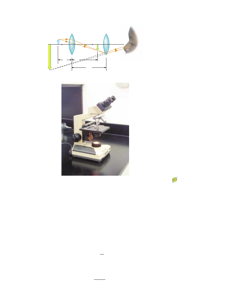
centimeters.  The  two  lenses  are  separated  by  a  distance  that  is  much  greater  than
either  f

o

or  f

e

.  The  object,  which  is  placed  just  outside  the  focal  point  of  the  objec-

tive, forms  a  real,  inverted  image  at  I

1

,  and  this  image  is  located  at  or  close  to  the

focal point  of  the  eyepiece.  The  eyepiece,  which  serves  as  a  simple  magnifier,
produces at  I

2

a  virtual,  enlarged  image  of  I

1

.  The  lateral  magnification  M

1

of  the

first image  is  $ q

1

/p

1

.  Note  from  Figure  36.44a  that  q

1

is  approximately  equal  to  L

and that the object is very close to the focal point of the objective: p

1

f

o

Thus, the

lateral magnification by the objective is

The angular magnification by the eyepiece for an object (corresponding to the image
at I

1

) placed at the focal point of the eyepiece is, from Equation 36.23,

m

e

"

25 cm

f

e

M

o

# $

L
f

o

S E C T I O N   3 6 . 9 •  The Compound Microscope

1161

Objective

Eyepiece

L

(a)

I

2

O

F

o

f

o

p

1

q

1

F

e

I

l

f

e

Active Figure 36.44 (a) Diagram of a compound microscope, which consists of an

objective lens and an eyepiece lens. (b) A compound microscope. The three-objective

turret allows the user to choose from several powers of magnification. Combinations of

eyepieces with different focal lengths and different objectives can produce a wide range

of magnifications.

At the Active Figures link

at http://www.pse6.com, you

can adjust the focal lengths of

the objective and eyepiece

lenses to see the effect on the

final image.

©

Tony 

Freeman/Photo 

Edit

(b)

The overall magnification of the image formed by a compound microscope is defined
as the product of the lateral and angular magnifications:

(36.24)

The negative sign indicates that the image is inverted.

The microscope has extended human vision to the point where we can view previ-

ously unknown details of incredibly small objects. The capabilities of this instrument
have  steadily  increased  with  improved  techniques  for  precision  grinding  of  lenses.  A
question often asked about microscopes is: “If one were extremely patient and careful,
would it be possible to construct a microscope that would enable the human eye to see
an  atom?”  The  answer  is  no,  as  long  as  light  is  used  to  illuminate  the  object.  The
reason is that, for an object under an optical microscope (one that uses visible light) to
be  seen,  the  object  must  be  at  least  as  large  as  a  wavelength  of  light.  Because  the
diameter of any atom is many times smaller than the wavelengths of visible light, the
mysteries of the atom must be probed using other types of “microscopes.”

The ability to use other types of waves to “see” objects also depends on wavelength.

We can illustrate this with water waves in a bathtub. Suppose you vibrate your hand in
the  water  until  waves  having  a  wavelength  of  about  15 cm  are  moving  along  the
surface. If you hold a small object, such as a toothpick, so that it lies in the path of the
waves, it does not appreciably disturb the waves; they continue along their path “oblivi-
ous” to it. Now suppose you hold a larger object, such as a toy sailboat, in the path of
the  15-cm  waves.  In  this  case,  the  waves  are  considerably  disturbed  by  the  object.
Because the toothpick is smaller than the wavelength of the waves, the waves do not
“see” it. (The intensity of the scattered waves is low.) Because it is about the same size
as the wavelength of the waves, however, the boat creates a disturbance. In other words,
the object acts as the source of scattered waves that appear to come from it.

Light waves behave in this same general way. The ability of an optical microscope to

view an object depends on the size of the object relative to the wavelength of the light
used  to  observe  it.  Hence,  we  can  never  observe  atoms  with  an  optical  microscope

2

because their dimensions are small (* 0.1 nm) relative to the wavelength of the light
(* 500 nm). 

36.10 The Telescope

Two  fundamentally  different  types  of 

telescopes exist;  both  are  designed  to  aid  in

viewing distant objects, such as the planets in our Solar System. The 

refracting tele-

scope uses a combination of lenses to form an image, and the reflecting telescope
uses a curved mirror and a lens.

The  lens  combination  shown  in  Figure  36.45a  is  that  of  a  refracting  telescope.

Like the compound microscope, this telescope has an objective and an eyepiece. The
two lenses are arranged so that the objective forms a real, inverted image of a distant
object  very  near  the  focal  point  of  the  eyepiece.  Because  the  object  is  essentially  at
infinity, this point at which I

1

forms is the focal point of the objective. The eyepiece

then forms, at I

2

, an enlarged, inverted image of the image at I

1

. In order to provide

the largest possible magnification, the image distance for the eyepiece is infinite. This
means  that  the  light  rays  exit  the  eyepiece  lens  parallel  to  the  principal  axis,  and
the image of the objective lens must form at the focal point of the eyepiece. Hence,
the two lenses are separated by a distance f

o

&

f

e

, which corresponds to the length of

the telescope tube.

M

o

m

e

" $

L
f

o


$

25 cm

f

e

%

1162

C H A P T E R   3 6 •  Image Formation

2

Single-molecule  near-field  optic  studies  are  routinely  performed  with  visible  light  having  wave-

lengths  of  about  500 nm.  The  technique  uses  very  small  apertures  to  produce  images  having  resolu-
tions as small as 10 nm.

The angular magnification of the telescope is given by #/#

o

, where #

o

is the angle

subtended  by  the  object  at  the  objective  and  # is  the  angle  subtended  by  the  final
image at the viewer’s eye. Consider Figure 36.45a, in which the object is a very great
distance to the left of the figure. The angle #

o

(to the left of the objective) subtended by

the  object  at  the  objective  is  the  same  as  the  angle  (to  the  right  of  the  objective)
subtended by the first image at the objective. Thus,

where the negative sign indicates that the image is inverted.

tan #

o

# #

o

# $

h!

f

o

S E C T I O N   3 6 . 10 •  The Telescope

1163

Objective lens

Eyepiece lens

f

o

f

e

f

e

F

e

F

o

I

1

F

e

'

θ

h'

(a)

I

2

o

θ

o

θ

At the Active Figures link

at http://www.pse6.com, you

can adjust the focal lengths of

the objective and eyepiece

lenses to see the effect on the

final image.

Active Figure 36.45 (a) Lens arrangement in a refracting telescope, with the object at

infinity. (b) A refracting telescope.

©

Tony 

Freeman/Photo 

Edit

(b)

The angle # subtended by the final image at the eye is the same as the angle that a

ray coming from the tip of I

1

and traveling parallel to the principal axis makes with the

principal axis after it passes through the lens. Thus,

We  have  not  used  a  negative  sign  in  this  equation  because  the  final  image  is  not
inverted; the object creating this final image I

2

is I

1

, and both it and I

2

point in the

same direction. Hence, the angular magnification of the telescope can be expressed as

(36.25)

and we see that the angular magnification of a telescope equals the ratio of the objec-
tive  focal  length  to  the  eyepiece  focal  length.  The  negative  sign  indicates  that  the
image is inverted.

When  we  look  through  a  telescope  at  such  relatively  nearby  objects  as  the  Moon

and the planets, magnification is important. However, individual stars in our galaxy are
so  far  away  that  they  always  appear  as  small  points  of  light  no  matter  how  great  the
magnification. A large research telescope that is used to study very distant objects must
have a great diameter to gather as much light as possible. It is difficult and expensive
to  manufacture  large  lenses  for  refracting  telescopes.  Another  difficulty  with  large
lenses is that their weight leads to sagging, which is an additional source of aberration.
These  problems  can  be  partially  overcome  by  replacing  the  objective  with  a  concave
mirror,  which  results  in  a  reflecting  telescope.  Because  light  is  reflected  from  the
mirror  and  does  not  pass  through  a  lens,  the  mirror  can  have  rigid  supports  on  the
back side. Such supports eliminate the problem of sagging.

Figure  36.46a  shows  the  design  for  a  typical  reflecting  telescope.  Incoming  light

rays pass down the barrel of the telescope and are reflected by a parabolic mirror at
the base. These rays converge toward point in the figure, where an image would be
formed. However, before this image is formed, a small, flat mirror M reflects the light
toward an opening in the side of the tube that passes into an eyepiece. This particular
design is said to have a Newtonian focus because Newton developed it. Figure 36.46b

"

#

#

o

"

h!/f

e

$

h!/f

o

" $

f

o

f

e

tan #

# # #

h!

f

e

1164

C H A P T E R   3 6 •  Image Formation

Eyepiece

M

A

Parabolic

mirror

Figure 36.46 (a) A Newtonian-focus reflecting telescope. (b) A reflecting telescope.

This type of telescope is shorter than that in Figure 36.45b.

Orion 

® 

Sky V

iew Pro

(a)

(b)


Content   ..  289  290  291  292   ..