Physics For Scientists And Engineers 6E - part 284


  Index      Production     Physics For Scientists And Engineers 6E


Search            


Content   ..  282  283  284  285   ..


Physics For Scientists And Engineers 6E - part 284


in this figure because the source is assumed to be very far from the mirror. We call
the  image  point  in  this  special  case  the 

focal  point and  the  image  distance  the

focal length f, where

(36.5)

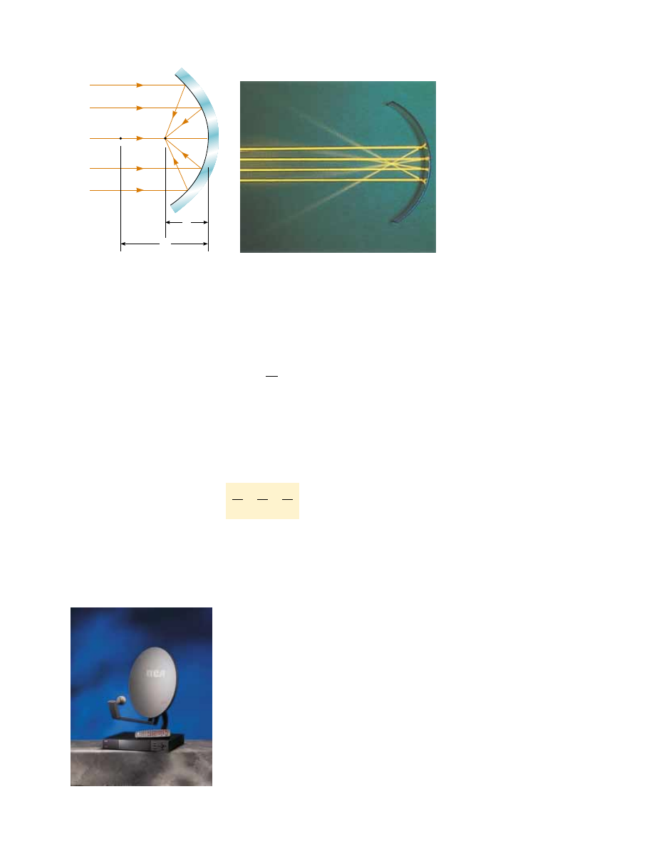
In Figure 36.8, the colored beams are traveling parallel to the principal axis and the
mirror reflects all three beams to the focal point. Notice that the point at which the
three beams intersect and the colors add is white. 

Focal length is a parameter particular to a given mirror and therefore can be used

to compare one mirror with another. The mirror equation can be expressed in terms
of the focal length:

(36.6)

Notice that the focal length of a mirror depends only on the curvature of the mirror
and not on the material from which the mirror is made. This is because the formation
of the image results from rays reflected from the surface of the material. The situation
is different for lenses; in that case the light actually passes through the material and
the focal length depends on the type of material from which the lens is made.

1
p

&

1

q

"

1
f

"

R

2

S E C T I O N   3 6 . 2 •  Images Formed by Spherical Mirrors

1133

C

F

R

f

(a)

Henry Leap and Jim Lehman

Figure 36.12 (a) Light rays from a distant object (: ') reflect from a concave

mirror through the focal point F. In this case, the image distance q

R/2 " f, where

is the focal length of the mirror. (b) Reflection of parallel rays from a concave mirror.

PITFALL PREVENTION 

36.2 The Focal Point Is

Not the Focus Point

The  focal  point  is  usually  not the
point at which the light rays focus
to  form  an  image.  The  focal
point is determined solely by the
curvature  of  the  mirror—it  does
not  depend  on  the  location  of
the  object  at  all.  In  general,  an
image  forms  at  a  point  different
from  the  focal  point  of  a  mirror
(or a lens). The only exception is
when  the  object  is  located  infi-
nitely far away from the mirror. 

A satellite-dish antenna is a concave reflector for televi-

sion signals from a satellite in orbit around the Earth. The

signals are carried by microwaves that, because the

satellite is so far away, are parallel when they arrive at the

dish. These waves reflect from the dish and are focused

on the receiver at the focal point of the dish.

Focal length

Mirror equation in terms of focal

length

Courtesy of Thomson Consumer Electronics

(b)

Convex Mirrors

Figure  36.13  shows  the  formation  of  an  image  by  a 

convex  mirror—that  is,  one

silvered  so  that  light  is  reflected  from  the  outer,  convex  surface.  This  is  sometimes
called a 

diverging mirror because the rays from any point on an object diverge after

reflection as though they were coming from some point behind the mirror. The image
in  Figure  36.13  is  virtual  because  the  reflected  rays  only  appear  to  originate  at  the
image point, as indicated by the dashed lines. Furthermore, the image is always upright
and  smaller  than  the  object.  This  type  of  mirror  is  often  used  in  stores  to  foil
shoplifters. A single mirror can be used to survey a large field of view because it forms a
smaller image of the interior of the store.

We do not derive any equations for convex spherical mirrors because we can use

Equations  36.2,  36.4,  and  36.6  for  either  concave  or  convex  mirrors  if  we  adhere  to
the following procedure. Let us refer to the region in which light rays move toward the
mirror as the front side of the mirror, and the other side as the back side. For example, in
Figures 36.11 and 36.13, the side to the left of the mirrors is the front side, and the
side to the right of the mirrors is the back side. Figure 36.14 states the sign conventions
for object and image distances, and Table 36.1 summarizes the sign conventions for all
quantities.

Ray Diagrams for Mirrors

The  positions  and  sizes  of  images  formed  by  mirrors  can  be  conveniently  deter-
mined  with  ray  diagrams. These  graphical  constructions  reveal  the  nature  of  the
image and can be used to check results calculated from the mirror and magnifica-
tion equations. To draw a ray diagram, we need to know the position of the object
and the locations of the mirror’s focal point and center of curvature. We then draw
three principal rays to locate the image, as shown by the examples in Figure 36.15.

1134

C H A P T E R   3 6 •  Image Formation

Front

Back

O

I

F

C

p

q

Figure 36.13 Formation of an image by a spherical convex mirror. The image formed

by the real object is virtual and upright.

Front, or

real, side

Reflected light

Back, or

virtual, side

p and q negative

No light

p and q positive

Incident light

Convex or

concave mirror

Figure 36.14 Signs of and for

convex and concave mirrors.

PITFALL PREVENTION 

36.3 Watch Your Signs

Success  in  working  mirror
problems  (as  well  as  problems
involving  refracting  surfaces  and
thin lenses) is largely determined
by  proper  sign  choices  when
substituting  into  the  equations.
The best way to become adept at
this  is  to  work  a  multitude  of
problems on your own. Watching
your  instructor  or  reading 
the  example  problems  is  no
substitute for practice.

Quantity

Positive When

Negative When

Object location (p)

Object is in front of 

Object is in back

mirror (real object)

of mirror (virtual object)

Image location (q)

Image is in front of 

Image is in back of

mirror (real image)

mirror (virtual image)

Image height (h!)

Image is upright

Image is inverted

Focal length ()  

Mirror is concave

Mirror is convex

and radius (R)

Magnification (M)

Image is upright

Image is inverted

Sign Conventions for Mirrors

Table 36.1

S E C T I O N   3 6 . 2 •  Images Formed by Spherical Mirrors

1135

(a)

1

2

3

C

F

O

Front

Back

I

Principal axis

(b)

1

2

3

C

F

O

I

Front

Back

(c)

C

F

O

I

1

2

3

Front

Back

Active Figure 36.15 Ray diagrams for spherical mirrors, along with corresponding

photographs of the images of candles. (a) When the object is located so that the center

of curvature lies between the object and a concave mirror surface, the image is real,

inverted, and reduced in size. (b) When the object is located between the focal point

and a concave mirror surface, the image is virtual, upright, and enlarged. (c) When the

object is in front of a convex mirror, the image is virtual, upright, and reduced in size.

Photos courtesy David Rogers

At the Active Figures link

at http://www.pse6.com, you

can move the objects and

change the focal length of the

mirrors to see the effect on the

images.

These  rays  all  start  from  the  same  object  point  and  are  drawn  as  follows.  We  may
choose any point on the object; here, we choose the top of the object for simplicity.
For  concave  mirrors  (see  Figs.  36.15a  and  36.15b),  we  draw  the  following  three
principal rays:

1136

C H A P T E R   3 6 •  Image Formation

• Ray  1  is  drawn  from  the  top  of  the  object  parallel  to  the  principal  axis  and  is

reflected through the focal point F.

• Ray 2 is drawn from the top of the object through the focal point and is reflected

parallel to the principal axis.

• Ray 3 is drawn from the top of the object through the center of curvature and is

reflected back on itself.

• Ray  1  is  drawn  from  the  top  of  the  object  parallel  to  the  principal  axis  and  is

reflected away from the focal point F.

• Ray 2 is drawn from the top of the object toward the focal point on the back side

of the mirror and is reflected parallel to the principal axis.

• Ray 3 is drawn from the top of the object toward the center of curvature on the

back side of the mirror and is reflected back on itself.

The intersection of any two of these rays locates the image. The third ray serves as

a  check  of  the  construction.  The  image  point  obtained  in  this  fashion  must  always
agree with the value of calculated from the mirror equation. With concave mirrors,
note  what  happens  as  the  object  is  moved  closer  to  the  mirror.  The  real,  inverted
image  in  Figure  36.15a  moves  to  the  left  as  the  object  approaches  the  focal  point.
When the object is at the focal point, the image is infinitely far to the left. However,
when  the  object  lies  between  the  focal  point  and  the  mirror  surface,  as  shown  in
Figure 36.15b, the image is virtual, upright, and enlarged. This latter situation applies
when you use a shaving mirror or a makeup mirror, both of which are concave. Your
face  is  closer  to  the  mirror  than  the  focal  point,  and  you  see  an  upright,  enlarged
image of your face.

For  convex  mirrors  (see  Fig.  36.15c),  we  draw  the  following  three  principal 

rays:

Quick  Quiz  36.3

You  wish  to  reflect  sunlight  from  a  mirror  onto  some

paper under a pile of wood in order to start a fire. Which would be the best choice for
the type of mirror? (a) flat (b) concave (c) convex.

Quick Quiz 36.4

Consider the image in the mirror in Figure 36.16. Based

on the appearance of this image, you would conclude that (a) the mirror is concave
and  the  image  is  real.  (b)  the  mirror  is  concave  and  the  image  is  virtual.  (c)  the
mirror  is  convex  and  the  image  is  real.  (d)  the  mirror  is  convex  and  the  image  is
virtual.

Figure 36.16 (Quick Quiz 36.4)

What type of mirror is this?

In a convex mirror, the image of an object is always virtual, upright, and reduced in

size as shown in Figure 36.15c. In this case, as the object distance decreases, the virtual
image increases in size and moves away from the focal point toward the mirror as the
object approaches the mirror. You should construct other diagrams to verify how image
position varies with object position.

PITFALL PREVENTION 

36.4 We Are Choosing a

Small Number of
Rays

huge number of light rays leave
each  point  on  an  object  (and
pass  through  each  point  on  an
image).  In  a  principal-ray  dia-
gram,  which  displays  the  charac-
teristics  of  the  image,  we  choose
only a few rays that follow simply
stated  rules.  Locating  the  image
by  calculation  complements  the
diagram.

NASA


Content   ..  282  283  284  285   ..