Physics For Scientists And Engineers 6E - part 266
 

  Index      Production     Physics For Scientists And Engineers 6E


Search            


Content   ..  264  265  266  267   ..


Physics For Scientists And Engineers 6E - part 266


Problems

1061

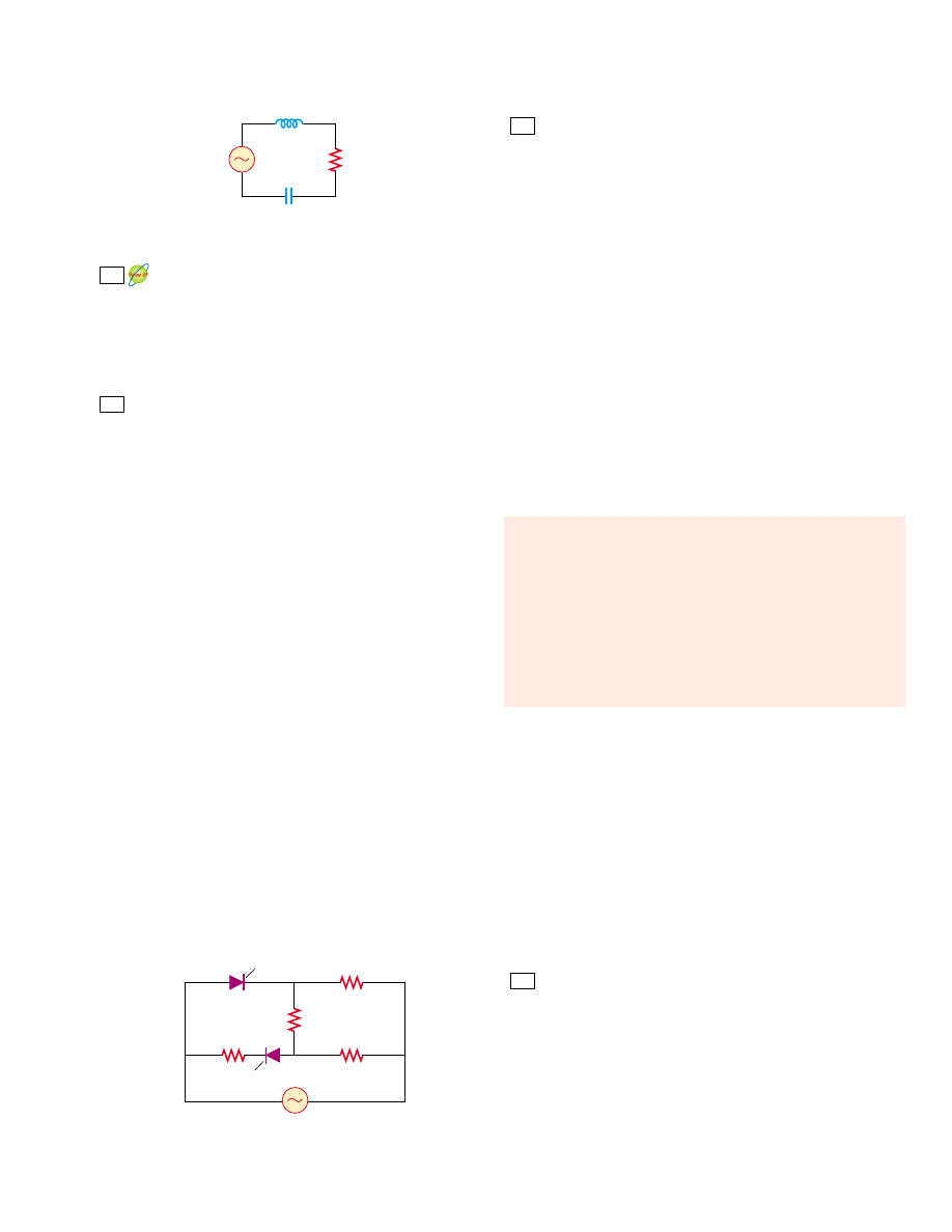
Figure P33.30

Figure P33.36

An AC voltage of the form !" (100 V) sin(1 000t)

is applied to a series RLC circuit. Assume the resistance is
400 (,  the  capacitance  is  5.00 ,F,  and  the  inductance  is
0.500 H.  Find  the  average  power  delivered  to  the  circuit.

32. A  series  RLC circuit  has  a  resistance  of  45.0 ( and  an

impedance of 75.0 (. What average power is delivered to
this circuit when !V

rms

"

210 V?

In  a  certain  series  RLC circuit,  I

rms

"

9.00  A,  !V

rms

"

180 V, and the current leads the voltage by 37.0°. (a) What
is  the  total  resistance  of  the  circuit?  (b)  Calculate  the
reactance of the circuit (X

L

*

X

C

).

34.

Suppose  you  manage  a  factory  that  uses  many  electric
motors.  The  motors  create  a  large  inductive  load  to  the
electric power line, as well as a resistive load. The electric
company  builds  an  extra-heavy  distribution  line  to  supply
you with a component of current that is 90° out of phase
with the voltage, as well as with current in phase with the
voltage. The electric company charges you an extra fee for
“reactive volt-amps,” in addition to the amount you pay for
the  energy  you  use.  You  can  avoid  the  extra  fee  by
installing  a  capacitor  between  the  power  line  and  your
factory. The following problem models this solution.

In  an  RL circuit,  a  120-V  (rms),  60.0-Hz  source  is  in

series with a 25.0-mH inductor and a 20.0-( resistor. What
are  (a)  the  rms  current  and  (b)  the  power  factor?
(c) What  capacitor  must  be  added  in  series  to  make  the
power  factor  1?  (d)  To  what  value  can  the  supply  voltage
be  reduced,  if  the  power  supplied  is  to  be  the  same  as
before the capacitor was installed?

35.

Suppose power ! is to be transmitted over a distance at a
voltage !with only 1.00% loss. Copper wire of what diam-
eter should be used for each of the two conductors of the
transmission line? Assume the current density in the con-
ductors is uniform.

36.

A diode is a device that allows current to be carried in only
one direction (the direction indicated by the arrowhead in
its circuit symbol). Find in terms of !and the average
power delivered to the diode circuit of Figure P33.36.

33.

31.

Section 33.7 Resonance in a Series RLC Circuit

An  RLC circuit  is  used  in  a  radio  to  tune  into  an  FM
station  broadcasting  at  99.7 MHz.  The  resistance  in  the
circuit  is  12.0 (,  and  the  inductance  is  1.40 ,H.  What
capacitance should be used?

38. The tuning circuit of an AM radio contains an LC combi-

nation. The inductance is 0.200 mH, and the capacitor is
variable, so that the circuit can resonate at any frequency
between 550 kHz and 1 650 kHz. Find the range of values
required for C.

39.

A  radar  transmitter  contains  an  LC  circuit  oscillating  at
1.00 + 10

10

Hz. (a) What capacitance will resonate with a

one-turn  loop  of  inductance  400 pH  at  this  frequency?
(b) If the capacitor has square parallel plates separated by
1.00 mm of air, what should the edge length of the plates
be?  (c)  What  is  the  common  reactance  of  the  loop  and
capacitor at resonance?

40. A series RLC circuit has components with following values:

" 20.0 mH, " 100 nF, " 20.0 (, and !V

max "

100 V,

with  !" !V

max

sin  #t. Find  (a)  the  resonant  frequency,

(b)  the  amplitude  of  the  current  at  the  resonant
frequency, (c) the of the circuit, and (d) the amplitude
of the voltage across the inductor at resonance.

41.

A 10.0-( resistor, 10.0-mH inductor, and 100-,F capacitor
are  connected  in  series  to  a  50.0-V  (rms)  source  having
variable frequency. Find the energy that is delivered to the
circuit  during  one  period  if  the  operating  frequency  is
twice the resonance frequency.

42.

A resistor R, inductor L, and capacitor are connected in
series  to  an  AC  source  of  rms  voltage  !and  variable
frequency. Find the energy that is delivered to the circuit
during one period if the operating frequency is twice the
resonance frequency.

43.

Compute  the  quality  factor  for  the  circuits  described
in Problems  22  and  23.  Which  circuit  has  the  sharper
resonance?

Section 33.8 The Transformer and Power

Transmission 

44. A  step-down  transformer  is  used  for  recharging  the

batteries  of  portable  devices  such  as  tape  players.  The
turns ratio inside the transformer is 13:1 and it is used with
120-V  (rms)  household  service.  If  a  particular  ideal
transformer  draws  0.350 A  from  the  house  outlet,  what
are (a) the voltage and (b) the current supplied to a tape
player  from  the  transformer?  (c)  How  much  power  is
delivered?
A transformer has N

1

"

350 turns and N

2

"

2 000 turns. If

the  input  voltage  is  !v(t) " (170  V)  cos  #t, what  rms
voltage is developed across the secondary coil?

46. A step-up transformer is designed to have an output voltage

of  2 200 V  (rms)  when  the  primary  is  connected  across
a 110-V  (rms)  source.  (a)  If  the  primary  winding  has
80 turns, how many turns are required on the secondary?
(b) If a load resistor across the secondary draws a current
of  1.50  A,  what  is  the  current  in  the  primary,  assuming 
ideal  conditions?  (c)  What  If?  If  the  transformer  actually

45.

37.

50.0 mH

V

40.0 

50.0


µ

F

µ

R

R

R

2R

V

Diode

Diode

1062

C H A P T E R   3 3 •  Alternating Current Circuits

has  an  efficiency  of  95.0%,  what  is  the  current  in  the  pri-
mary when the secondary current is 1.20 A?

47.

In  the  transformer  shown  in  Figure  P33.47,  the  load
resistor  is  50.0 (.  The  turns  ratio  N

1

:N

2

is  5:2,  and  the

source voltage is 80.0 V (rms). If a voltmeter across the load
measures 25.0 V (rms), what is the source resistance R

s

?

voltage is

(b) What value does this ratio approach as the frequency
decreases  toward  zero?  What  value  does  this  ratio
approach as the frequency increases without limit? (c) At
what frequency is the ratio equal to one half?

The  RC high-pass  filter  shown  in  Figure  33.25  has

a resistance  " 0.500 (.  (a)  What  capacitance  gives  an
output signal that has half the amplitude of a 300-Hz input
signal?  (b)  What  is  the  ratio  (!V

out

/!V

in

)  for  a  600-Hz

signal? You may use the result of Problem 51.

54. The  RC low-pass  filter  shown  in  Figure  33.26  has  a

resistance  " 90.0 ( and  a  capacitance  " 8.00 nF.
Calculate the ratio (!V

out

/!V

in

) for an input frequency of

(a) 600 Hz  and  (b)  600 kHz.  You  may  use  the  result  of
Problem 52.

55.

The  resistor  in  Figure  P33.55  represents  the  midrange
speaker  in  a  three-speaker  system.  Assume  its  resistance  to
be  constant  at  8.00 (.  The  source  represents  an  audio
amplifier  producing  signals  of  uniform  amplitude  !V

in

"

10.0 V at all audio frequencies. The inductor and capacitor
are to function as a bandpass filter with !V

out

/!V

in

"

1/2

at  200 Hz  and  at  4 000 Hz.  (a)  Determine  the  required
values of and C. (b) Find the maximum value of the ratio
!

V

out

/!V

in

.  (c)  Find  the  frequency  f

0

at  which  the  ratio

has  its  maximum  value.  (d) Find  the  phase  shift  between
!

V

in

and !V

out

at 200 Hz, at f

0

, and at 4 000 Hz. (e) Find

the  average  power  transferred  to  the  speaker  at  200 Hz,
at f

0

, and at 4 000 Hz. (f) Treating the filter as a resonant

circuit, find its quality factor.

53.

V


out

V


in

"

1/#C

R


2

$

"

1

#

C

#

2

Figure P33.47

Figure P33.56

Figure P33.55

N

2

N

1

R

L

V

s

R

s

R

V

in

L

C

V

out

V

max

t

v

+

V

max

48.

The  secondary  voltage  of  an  ignition  transformer  in  a
furnace  is  10.0 kV.  When  the  primary  operates  at  an  rms
voltage of 120 V, the primary impedance is 24.0 ( and the
transformer  is  90.0%  efficient.  (a)  What  turns  ratio  is
required? What are (b) the current in the secondary and
(c) the impedance in the secondary?

49.

A transmission line that has a resistance per unit length of
4.50 + 10

*

4

(

/m is to be used to transmit 5.00 MW over

400  miles  (6.44 + 10

5

m).  The  output  voltage  of  the

generator  is  4.50 kV.  (a)  What  is  the  line  loss  if  a  trans-
former is used to step up the voltage to 500 kV? (b) What
fraction of the input power is lost to the line under these
circumstances?  (c)  What  If?  What  difficulties  would  be
encountered in attempting to transmit the 5.00 MW at the
generator voltage of 4.50 kV?

Section 33.9 Rectifiers and Filters
50. 
One  particular  plug-in  power  supply  for  a  radio  looks

similar to the one shown in Figure 33.23 and is marked
with  the  following  information:  Input  120 V  AC  8 W
Output  9 V  DC  300 mA.  Assume  that  these  values  are
accurate  to  two  digits.  (a)  Find  the  energy  efficiency  of
the device when the radio is operating. (b) At what rate
does the device produce wasted energy when the radio is
operating?  (c)  Suppose  that  the  input  power  to  the
transformer is 8.0 W when the radio is switched off and
that  energy  costs  $0.135/kWh  from  the  electric  com-
pany.  Find  the  cost  of  having  six  such  transformers
around the house, plugged in for thirty-one days. 

51.Consider  the  filter  circuit  shown  in  Figure  33.25a.

(a) Show that the ratio of the output voltage to the input
voltage is

(b) What value does this ratio approach as the frequency
decreases  toward  zero?  What  value  does  this  ratio
approach as the frequency increases without limit? (c) At
what frequency is the ratio equal to one half?

52. Consider  the  filter  circuit  shown  in  Figure  33.26a.

(a) Show that the ratio of the output voltage to the input

V


out

V


in

"

R

R


2

$

"

1

#

C

#

2

Additional Problems

56.

Show that the rms value for the sawtooth voltage shown in
Figure P33.56 is 

.

!

V

max


/


3

A  series  RLC circuit  consists  of  an  8.00-( resistor,  a

5.00-,F  capacitor,  and  a  50.0-mH  inductor.  A  variable

57.

Problems

1063

62.

In  the  circuit  shown  in  Figure  P33.62,  assume  that  all
parameters except for are given. (a) Find the current as
a  function  of  time.  (b)  Find  the  power  delivered  to  the
circuit. (c) Find the current as a function of time after only
switch  1  is  opened.  (d)  After  switch  2  is  also opened,  the
current and voltage are in phase. Find the capacitance C.
(e) Find the impedance of the circuit when both switches
are open. (f) Find the maximum energy stored in the ca-
pacitor during oscillations. (g) Find the maximum energy
stored in the inductor during oscillations. (h) Now the fre-
quency  of  the  voltage  source  is  doubled.  Find  the  phase
difference  between  the  current  and  the  voltage.  (i)  Find
the frequency that makes the inductive reactance half the
capacitive reactance.

frequency source applies an emf of 400 V (rms) across the
combination. Determine the power delivered to the circuit
when  the  frequency  is  equal  to  half  the  resonance
frequency.

58.

A capacitor, a coil, and two resistors of equal resistance are
arranged in an AC circuit, as shown in Figure P33.58. An
AC source provides an emf of 20.0 V (rms) at a frequency
of  60.0 Hz.  When  the  double-throw  switch  S  is  open,  as
shown in the figure, the rms current is 183 mA. When the
switch  is  closed  in  position  1,  the  rms  current  is  298 mA.
When the switch is closed in position 2, the rms current is
137 mA. Determine the values of RC, and L. Is more than
one set of values possible?

Figure P33.61

Figure P33.62

Figure P33.64

Eddie Hironaka/Getty Images

3.00 mH

100 

200 

45.0 V(rms)

200

   F

µ

R

L

S

1

C

S

2

v() = ∆V

max

 cos 

   t

ω

R

L

C

R

1

2

20.0 V (rms)

60.0 Hz

S

Figure P33.58

59.

To determine the inductance of a coil used in a research
project, a student first connects the coil to a 12.0-V battery
and  measures  a  current  of  0.630 A.  The  student  then
connects  the  coil  to  a  24.0-V  (rms),  60.0-Hz  generator
and measures  an  rms  current  of  0.570 A.  What  is  the
inductance?

60.

Review  problem.  One  insulated  conductor  from  a  house-
hold  extension  cord  has  mass  per  length  19.0 g/m.  A
section  of  this  conductor  is  held  under  tension  between
two clamps. A subsection is located in a region of magnetic
field of magnitude 15.3 mT perpendicular to the length of
the  cord.  The  wire  carries  an  AC  current  of  9.00 A  at
60.0 Hz.  Determine  some  combination  of  values  for  the
distance  between  the  clamps  and  the  tension  in  the  cord
so  that  the  cord  can  vibrate  in  the  lowest-frequency
standing-wave vibrational state.

61.

In  Figure  P33.61,  find  the  rms  current  delivered  by  the
45.0-V (rms) power supply when (a) the frequency is very
large and (b) the frequency is very small.

63.

An  80.0-( resistor  and  a  200-mH  inductor  are  connected
in parallel across a 100-V (rms), 60.0-Hz source. (a) What is
the rms current in the resistor? (b) By what angle does the
total current lead or lag behind the voltage?

64. Make  an  order-of-magnitude  estimate  of  the  electric

current that the electric company delivers to a town (Figure
P33.64)  from  a  remote  generating  station.  State  the  data
you  measure  or  estimate.  If  you  wish,  you  may  consider  a
suburban bedroom community of 20 000 people.

Consider a series RLC circuit having the following circuit
parameters:  " 200 (,  " 663 mH,  and  " 26.5 ,F.
The  applied  voltage  has  an  amplitude  of  50.0 V  and  a
frequency  of  60.0 Hz.  Find  the  following  amplitudes:
(a) The  current  I

max

including  its  phase  constant  -

relative  to  the  applied  voltage  !v,  (b)  the  voltage  !V

R

65.

1064

C H A P T E R   3 3 •  Alternating Current Circuits

across  the  resistor  and  its  phase  relative  to  the  current,
(c) the  voltage  !V

C

across  the  capacitor  and  its  phase

relative to the current, and (d) the voltage !V

L

across the

inductor and its phase relative to the current.

66.

A  voltage  !" (100 V) sin #(in  SI  units)  is  applied
across a series combination of a 2.00-H inductor, a 10.0-,F
capacitor, and a 10.0-( resistor. (a) Determine the angular
frequency #

0

at which the power delivered to the resistor

is  a  maximum.  (b)  Calculate  the  power  delivered  at  that
frequency. (c) Determine the two angular frequencies #

1

and  #

2

at  which  the  power  is  half  the  maximum  value.

[The of the circuit is #

0

/(#

2

*

#

1

).]

Impedance  matching. Example  28.2  showed  that  maximum
power is transferred when the internal resistance of a DC
source is equal to the resistance of the load. A transformer
may be used to provide maximum power transfer between
two AC circuits that have different impedances Z1 and Z2,
where  1  and  2  are  subscripts  and  the  Z’s  are  italic  (as  in
the  centered  equation).  (a) Show that  the  ratio  of  turns
N

1

/N

2

needed to meet this condition is 

(b) Suppose you want to use a transformer as an impedance-
matching  device  between  an  audio  amplifier  that  has  an
output  impedance  of  8.00 k( and  a  speaker  that  has  an
input  impedance  of  8.00 (.  What  should  your  N

1

/N

2

ratio be?

68.

A power supply with !V

rms

"

120 V is connected between

points and in Figure P33.26. At what frequency will it
deliver a power of 250 W?

69.

Figure P33.69a shows a parallel RLC circuit, and the corre-
sponding phasor diagram is given in Figure P33.69b. The
instantaneous  voltages  (and  rms  voltages)  across  each  of
the  three  circuit  elements  are  the  same,  and  each  is  in

N


1

N


2

"

Z

1

Z


2

67.

phase with the current through the resistor. The currents
in and lead or lag behind the current in the resistor, as
shown  in  Figure  P33.69b.  (a)  Show  that  the  rms  current
delivered by the source is

(b) Show that the phase angle - between !V

rms

and I

rms 

is 

70.

An  80.0-( resistor,  a  200-mH  inductor,  and  a  0.150-,F
capacitor  are  connected  in  parallel across  a  120-V  (rms)
source  operating  at  374 rad/s.  (a)  What  is  the  resonant
frequency of the circuit? (b) Calculate the rms current in
the resistor, inductor, and capacitor. (c) What rms current
is  delivered  by  the  source?  (d)  Is  the  current  leading  or
lagging behind the voltage? By what angle?

71.

A  series  RLC circuit  is  operating  at  2 000 Hz.  At  this

frequency,  X

L

"

X

C

"

1 884 (.  The  resistance  of  the

circuit is 40.0 (. (a) Prepare a table showing the values of
X

L

,  X

C

,  and  for  " 300,  600,  800,  1 000,  1 500,  2 000,

3 000, 4 000, 6 000, and 10 000 Hz. (b) Plot on the same set
of axes X

L

X

C

, and as a function of ln f.

A  series  RLC circuit  in  which  " 1.00 (,  "

1.00 mH,  and  " 1.00 nF  is  connected  to  an  AC  source
delivering  1.00 V  (rms).  Make  a  precise  graph  of  the
power  delivered  to  the  circuit  as  a  function  of  the
frequency  and  verify  that  the  full  width  of  the  resonance
peak at half-maximum is R/2%L.

73.

Suppose the high-pass filter shown in Figure 33.25 has

" 1 000 ( and  " 0.050 0 ,F.  (a)  At  what  frequency
does  !V

out

/!V

in

"

?  (b)  Plot  log

10

(!V

out

/!V

in

)  versus

log

10

)  over  the  frequency  range  from  1 Hz  to  1 MHz.

(This log–log plot of gain versus frequency is known as a
Bode plot.)

Answers to Quick Quizzes
33.1 
(a).  The  phasor  in  part  (a)  has  the  largest  projection

onto the vertical axis.

33.2 (b).  The  phasor  in  part  (b)  has  the  smallest-magnitude

projection onto the vertical axis.

33.3 (c).  The  average  power  is  proportional  to  the  rms

current,  which,  as  Figure  33.5  shows,  is  nonzero  even
though the average current is zero. Condition (a) is valid
only for an open circuit, and conditions (b) and (d) can
not be true because i

av

"

0 if the source is sinusoidal.

33.4 (b). For low frequencies, the reactance of the inductor is

small  so  that  the  current  is  large.  Most  of  the  voltage
from  the  source  is  across  the  bulb,  so  the  power
delivered to it is large.

33.5 (a). For high frequencies, the reactance of the capacitor

is small so that the current is large. Most of the voltage
from  the  source  is  across  the  bulb,  so  the  power
delivered to it is large.

33.6 (b). For low frequencies, the reactance of the capacitor

is large so that very little current exists in the capacitor

1

2

72.

tan - " R  

"

1

X

C

*

1

X

L

#

I


rms

"

V


rms


%

1

R


2

$

"

#

*

1

#

L

#

2

&

1/2

Figure P33.69

R

L

C

(a)

(b)

I

C

I

R

I

L

V

V


Content   ..  264  265  266  267   ..