Physics For Scientists And Engineers 6E - part 235


  Index      Production     Physics For Scientists And Engineers 6E


Search            


Content   ..  233  234  235  236   ..


Physics For Scientists And Engineers 6E - part 235


SECTION 3 0.3 •  Ampère’s Law

937

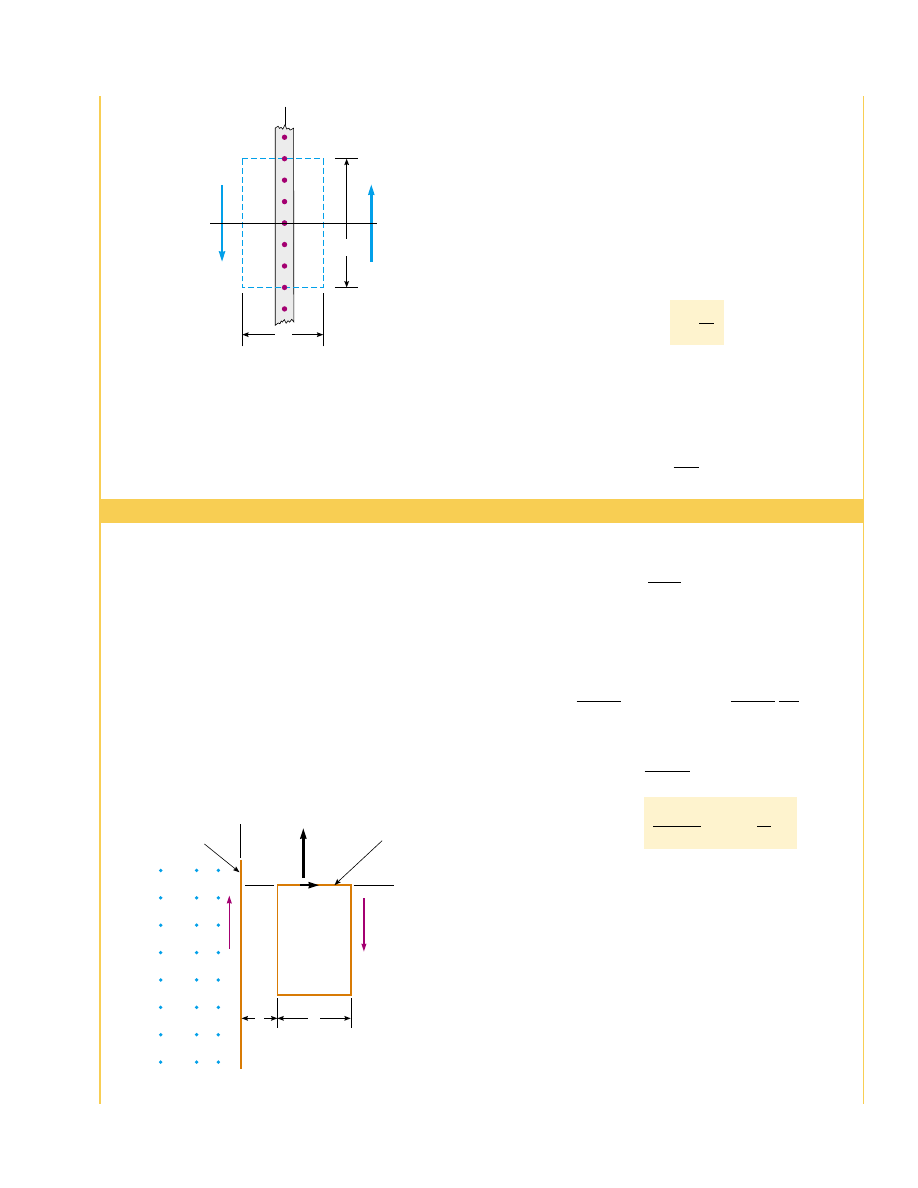
Wire  1  in  Figure  30.16  is  oriented  along  the  axis  and
carries a steady current I

1

. A rectangular loop located to the

right  of  the  wire  and  in  the  xy plane  carries  a  current  I

2

.

Find the magnetic force exerted by wire 1 on the top wire of
length in the loop, labeled “Wire 2” in the figure.

Solution You  may  be  tempted  to  use  Equation  30.12
to obtain the force exerted on a small segment of length
dx of  wire  2.  However,  this  equation  applies  only  to  two
parallel  wires  and  cannot  be  used  here.  The  correct
approach  is  to  consider  the  force  exerted  by  wire  1  on  a
small  segment  d

s of  wire  2  by  using  Equation  29.4.  This

force  is  given  by  d

F

B

"

I d

s ! B,  where  I

2

and 

B is

the magnetic field created by the current in wire 1 at the
position of d

s. From Ampère’s law, the field at a distance x

Figure 30.15 (Example 30.6) End view of an infinite current

sheet lying in the yz plane, where the current is in the direc-

tion (out of the page). This view shows the direction of on

both sides of the sheet.

Figure 30.16 (Example 30.7) A wire on one side of a rectangu-

lar loop lying near a current-carrying wire experiences a force.

from wire 1 (see Eq. 30.14) is

where  the  unit  vector  ' kˆ is  used  to  indicate  that  the  field
due to the current in wire 1 at the position of d

s points into

the page. Because wire 2 is along the axis, d

s " dx iˆ, and

we find that

Integrating over the limits to gives

(1)

The  force  on  wire  2  points  in  the  positive  direction,  as
indicated by the unit vector jˆ and as shown in Figure 30.16.

What If?

What if the wire loop is moved to the left in Figure

30.16  until  a 0?  What  happens  to  the  magnitude  of  the
force on the wire?

Answer The  force  should  become  stronger  because  the
loop  is  moving  into  a  region  of  stronger  magnetic  field.
Equation  (1)  shows  that  the  force  not  only  becomes
stronger but the magnitude of the force becomes infinite as
: 0! Thus, as the loop is moved to the left in Figure 30.16,
the loop should be torn apart by the infinite upward force
on the top side and the corresponding downward force on
the bottom side! Furthermore, the force on the left side is

#

0

I

1

I

2

2$

 ln 

&

 1 *

b

a

'

 ˆ

j

F

B

"

F

B

"

#

0

I

1

I

2

2$

  ln x

(

a

a*b

ˆj

d


F

B

"

#

0

I

1

I

2

2$x

 [ˆ

i ! ('ˆk )]


dx "

#

0

I

1

I

2

2$


dx

x

  ˆ

j

B "

#

0

I


1

2$x

 ('ˆ


k )  

!

w

x

z

J

s

(out of paper)

B

B

Wire 1

Wire 2

×

y

×

×

×

×

×

×

×

×

×

×

×

×

×

×

×

×

×

×

×

×

×

×

×

×

×

×

×

×

×

×

×

I

1

x

I

2

ds

b

a

F

B

Example 30.7 The Magnetic Force on a Current Segment

hence  the  field  should  not  vary  from  point  to  point.  The
only  choices  of  field  direction  that  are  reasonable  in  this
situation  are  either  perpendicular  or  parallel  to  the  sheet.
However,  a  perpendicular  field  would  pass  through  the
current,  which  is  inconsistent  with  the  Biot–Savart  law.
Assuming a field that is constant in magnitude and parallel
to the plane of the sheet, we obtain

This result shows that the magnetic field is independent of
distance  from  the  current  sheet,  as  we  suspected.  The
expression for the magnitude of the magnetic field is similar
in form to that for the magnitude of the electric field due to
an infinite sheet of charge (Example 24.8):

"

/

20

0

#

0


J

s

2

"

2B! " #

0


J

s


!

%


B(ds " #


0

" #

0


J

s


!

along the direction of these paths is zero. By symmetry, the
magnetic field is constant over the sides of length ! because
every  point  on  the  infinitely  large  sheet  is  equivalent,  and

30.4 The Magnetic Field of a Solenoid

solenoid is  a  long  wire  wound  in  the  form  of  a  helix.  With  this  configuration,  a

reasonably  uniform  magnetic  field  can  be  produced  in  the  space  surrounded  by  the
turns  of  wire—which  we  shall  call  the  interior  of  the  solenoid—when  the  solenoid
carries a current. When the turns are closely spaced, each can be approximated as a
circular loop, and the net magnetic field is the vector sum of the fields resulting from
all the turns.

Figure 30.17 shows the magnetic field lines surrounding a loosely wound solenoid.

Note  that  the  field  lines  in  the  interior  are  nearly  parallel  to  one  another,  are
uniformly distributed, and are close together, indicating that the field in this space is
strong and almost uniform.

If  the  turns  are  closely  spaced  and  the  solenoid  is  of  finite  length,  the  magnetic

field lines are as shown in Figure 30.18a. This field line distribution is similar to that
surrounding a bar magnet (see Fig. 30.18b). Hence, one end of the solenoid behaves
like the north pole of a magnet, and the opposite end behaves like the south pole. As
the length of the solenoid increases, the interior field becomes more uniform and the
exterior  field  becomes  weaker.  An  ideal  solenoid  is  approached  when  the  turns  are
closely  spaced  and  the  length  is  much  greater  than  the  radius  of  the  turns.  Figure
30.19 shows a longitudinal cross section of part of such a solenoid carrying a current I.
In this case, the external field is close to zero, and the interior field is uniform over a
great volume.

938

CHAPTE R 3 0 •  Sources of the Magnetic Field

toward  the  left  and  should  also  become  infinite.  This  is
larger  than  the  force  toward  the  right  on  the  right  side
because this side is still far from the wire, so the loop should
be pulled into the wire with infinite force!

Does  this  really  happen?  In  reality,  it  is  impossible  for

: 0  because  both  wire  1  and  wire  2  have  finite  sizes,  so
that the separation of the centers of the two wires is at least
the sum of their radii.

A  similar  situation  occurs  when  we  re-examine  the

magnetic field due to a long straight wire, given by Equation
30.5. If we could move our observation point infinitesimally
close to the wire, the magnetic field would become infinite!
But in reality, the wire has a radius, and as soon as we enter
the wire, the magnetic field starts to fall off as described by
Equation  30.15 — approaching  zero  as  we  approach  the
center of the wire.

Exterior

Interior

(a)

S

N

Figure 30.17 The magnetic field

lines for a loosely wound solenoid.

Figure 30.18 (a) Magnetic field lines for a tightly wound solenoid of finite length,

carrying a steady current. The field in the interior space is strong and nearly uniform.

Note that the field lines resemble those of a bar magnet, meaning that the solenoid

effectively has north and south poles. (b) The magnetic field pattern of a bar magnet,

displayed with small iron filings on a sheet of paper.

Henry Leap and Jim Lehman

(b)

If  we  consider  the  amperian  loop  perpendicular  to  the  page  in  Figure  30.19,

surrounding the ideal solenoid, we see that it encloses a small current as the charges in
the wire move coil by coil along the length of the solenoid. Thus, there is a nonzero
magnetic  field  outside  the  solenoid.  It  is  a  weak  field,  with  circular  field  lines,  like
those due to a line of current as in Figure 30.4. For an ideal solenoid, this is the only
field external to the solenoid. We can eliminate this field in Figure 30.19 by adding a
second layer of turns of wire outside the first layer, with the current carried along the
axis of the solenoid in the opposite direction compared to the first layer. Then the net
current along the axis is zero.

We  can  use  Ampère’s  law  to  obtain  a  quantitative  expression  for  the  interior

magnetic field in an ideal solenoid. Because the solenoid is ideal, 

B in the interior

space  is  uniform  and  parallel  to  the  axis,  and  the  magnetic  field  lines  in  the
exterior space  form  circles  around  the  solenoid.  The  planes  of  these  circles  are
perpendicular  to  the  page.  Consider  the  rectangular  path  of  length  ! and  width
shown  in  Figure  30.19.  We  can  apply  Ampère’s  law  to  this  path  by  evaluating
the integral  of 

B ( ds over  each  side  of  the  rectangle.  The  contribution  along

side 3 is zero  because  the  magnetic  field  lines  are  perpendicular  to  the
path in this region.  The  contributions  from  sides  2  and 4  are  both  zero,  again
because 

B is perpendicular  to  ds along  these  paths,  both  inside  and  outside  the

solenoid. Side 1 gives  a  contribution  to  the  integral  because  along  this  path 

B is

uniform  and  parallel  to  d

s.  The  integral  over  the  closed  rectangular  path  is

therefore

The  right  side  of  Ampère’s  law  involves  the  total  current  I  through  the  area

bounded by the path of integration. In this case, the total current through the rectan-
gular path equals the current through each turn multiplied by the number of turns. If
is the number of turns in the length !, the total current through the rectangle is NI.
Therefore, Ampère’s law applied to this path gives

(30.17)

where N/! is the number of turns per unit length.

" #


N

!


 " #

0

nI

%


B(d


s " B! " #

0

NI

%


B(ds "

!

path


1

B(d


s " B 

!

path


1

ds B!

SECTION 3 0.4 •  The Magnetic Field of a Solenoid

939

B

×
×
×
×
×
×
×
×

×

3

2

4

1

!

w

×

×

Figure 30.19 Cross-sectional view of an ideal solenoid,

where the interior magnetic field is uniform and the

exterior field is close to zero. Ampère’s law applied to

the circular path near the bottom whose plane is

perpendicular to the page can be used to show that

there is a weak field outside the solenoid. Ampère’s law

applied to the rectangular dashed path in the plane of

the page can be used to calculate the magnitude of the

interior field.

Magnetic field inside a solenoid

30.5 Magnetic Flux

The flux associated with a magnetic field is defined in a manner similar to that used to
define  electric  flux  (see  Eq.  24.3).  Consider  an  element  of  area  dA on  an  arbitrarily
shaped surface, as shown in Figure 30.20. If the magnetic field at this element is 

B, the

magnetic flux through the element is 

B ( dA, where dA is a vector that is perpendicular

to the surface and has a magnitude equal to the area dA. Therefore, the total magnetic
flux 1

B

through the surface is

(30.18)

Consider the special case of a plane of area in a uniform field 

B that makes an

angle ! with dA. The magnetic flux through the plane in this case is

(30.19)

If the magnetic field is parallel to the plane, as in Figure 30.21a, then ! " 90° and the
flux through the plane is zero. If the field is perpendicular to the plane, as in Figure
30.21b, then ! " 0 and the flux through the plane is 

BA (the maximum value).

The  unit  of  magnetic  flux  is  T ( m

2

,  which  is  defined  as  a  weber (Wb);  1 Wb "

1 T ( m

2

.

1

B

"

BA cos !

1

B

"  

!


B(d


A

940

CHAPTE R 3 0 •  Sources of the Magnetic Field

We  also  could  obtain  this  result  by  reconsidering  the  magnetic  field  of  a  toroid

(see Example 30.5). If the radius of the torus in Figure 30.14 containing turns is
much  greater  than  the  toroid’s  cross-sectional  radius  a,  a  short  section  of  the  toroid
approximates a solenoid for which N/2$r. In this limit, Equation 30.16 agrees with
Equation 30.17.

Equation 30.17 is valid only for points near the center (that is, far from the ends)

of a very long solenoid. As you might expect, the field near each end is smaller than
the value given by Equation 30.17. At the very end of a long solenoid, the magnitude of
the field is half the magnitude at the center (see Problem 32).

Quick  Quiz  30.6

Consider  a  solenoid  that  is  very  long  compared  to  the

radius. Of the following choices, the most effective way to increase the magnetic field
in the interior of the solenoid is to (a) double its length, keeping the number of turns
per unit length constant, (b) reduce its radius by half, keeping the number of turns per
unit length constant, (c) overwrapping the entire solenoid with an additional layer of
current-carrying wire.

B

A

θ

Figure 30.20 The magnetic flux

through an area element dA is

B ( dA " B dA cos 

!

, where d

A is a

vector perpendicular to the

surface.

(a)

(b)

B

A

B

A

Active Figure 30.21 Magnetic flux through a plane lying in a magnetic field.

(a) The flux through the plane is zero when the magnetic field is parallel to the plane

surface. (b) The flux through the plane is a maximum when the magnetic field is

perpendicular to the plane.

At the Active Figures link

at http://www.pse6.com, you

can rotate the plane and

change the value of the field to

see the effect on the flux.

Definition of magnetic flux


Content   ..  233  234  235  236   ..