Physics For Scientists And Engineers 6E - part 208
 

  Index      Production     Physics For Scientists And Engineers 6E


Search            


Content   ..  206  207  208  209   ..


Physics For Scientists And Engineers 6E - part 208


Answers to Quick Quizzes

829

Example 26.7, in which the battery was removed from the
circuit before the dielectric was introduced.)

70.

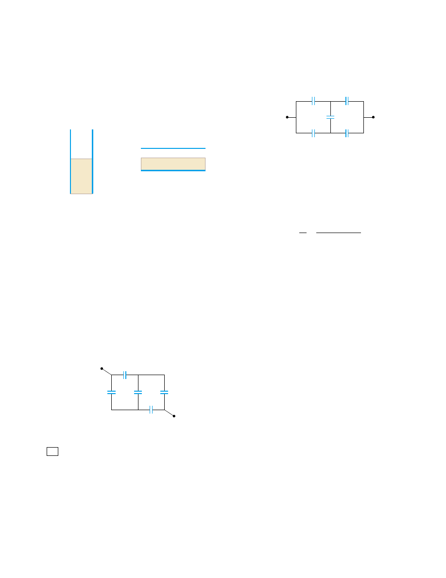
A vertical parallel-plate capacitor is half filled with a dielec-
tric for which the dielectric constant is 2.00 (Fig. P26.70a).
When  this  capacitor  is  positioned  horizontally,  what
fraction of it should be filled with the same dielectric (Fig.
P26.70b)  in  order  for  the  two  capacitors  to  have  equal
capacitance?

75.

Determine the equivalent capacitance of the combination
shown in Figure P26.75. (Suggestion: Consider the symme-
try involved.)

(b)

(a)

Figure P26.70

a

b

2.00 

µ

F

4.00 

µ

F

2.00 

µ

F

4.00 

µ

F

8.00 

µ

F

µ

µ

µ

µ

µ

Figure P26.72

C

C

3C

2C

2C

Figure P26.75

71.

Capacitors C

1

#

6.00 %F and C

2

#

2.00 %F are charged as

a parallel combination across a 250-V battery. The capaci-
tors  are  disconnected  from  the  battery  and  from  each
other. They are then connected positive plate to negative
plate  and  negative  plate  to  positive  plate.  Calculate  the
resulting charge on each capacitor.

72.

Calculate the equivalent capacitance between the points a
and in Figure P26.72. Note that this is not a simple series
or  parallel  combination.  (Suggestion: Assume  a  potential
difference  !between  points  and  b. Write  expressions
for !V

ab

in terms of the charges and capacitances for the

various possible pathways from to b, and require conser-
vation  of  charge  for  those  capacitor  plates  that  are  con-
nected to each other.)

The  inner  conductor  of  a  coaxial  cable  has  a  radius  of
0.800 mm,  and  the  outer  conductor’s  inside  radius  is
3.00 mm. The space between the conductors is filled with
polyethylene, which has a dielectric constant of 2.30 and a
dielectric  strength  of  18.0 * 10

6

V/m.  What  is  the  maxi-

mum potential difference that this cable can withstand?

74.

You are optimizing coaxial cable design for a major manu-
facturer.  Show  that  for  a  given  outer  conductor  radius  b,
maximum potential difference capability is attained when
the radius of the inner conductor is b/e where is the
base of natural logarithms.

73.

76.

Consider two longparallel, and oppositely charged wires
of  radius  with  their  centers  separated  by  a  distance  D.
Assuming  the  charge  is  distributed  uniformly  on  the
surface  of  each  wire,  show  that  the  capacitance  per  unit
length of this pair of wires is

77.

Example  26.2  explored  a  cylindrical  capacitor  of  length  !
and  radii  and  of  the  two  conductors.  In  the  What If?
section,  it  was  claimed  that  increasing  ! by  10%  is  more
effective in terms of increasing the capacitance than increas-
ing by 10% if , 2.85a. Verify this claim mathematically.

Answers to Quick Quizzes
26.1 
(d). The capacitance is a property of the physical system

and  does  not  vary  with  applied  voltage.  According  to
Equation  26.1,  if  the  voltage  is  doubled,  the  charge  is
doubled.

26.2 (a).  When  the  key  is  pressed,  the  plate  separation  is

decreased  and  the  capacitance  increases.  Capacitance
depends only on how a capacitor is constructed and not
on the external circuit.

26.3 (a).  When  connecting  capacitors  in  series,  the  inverses

of  the  capacitances  add,  resulting  in  a  smaller  overall
equivalent capacitance.

26.4 (a).  When  capacitors  are  connected  in  series,  the  volt-

ages add, for a total of 20 V in this case. If they are com-
bined in parallel, the voltage across the combination is
still 10 V.

26.5 (b). For a given voltage, the energy stored in a capacitor

is proportional to CC(!)

2

/2. Thus, you want to

maximize  the  equivalent  capacitance.  You  do  this  by
connecting  the  three  capacitors  in  parallel,  so  that  the
capacitances add.

26.6 (a) decreases (Eq. 26.3). (b) stays the same because

there  is  no  place  for  the  charge  to  flow.  (c)  remains
constant (see Eq. 24.8 and the paragraph following it).
(d) !increases because !/Cis constant (part
b),  and  decreases  (part  a).  (e)  The  energy  stored  in
the  capacitor  is  proportional  to  both  and  !(Eq.

C

!

#

()

0

ln[(d)/d]

830

C H A P T E R   2 6 •  Capacitance and Dielectrics

26.11) and thus increases. The additional energy comes
from the work you do in pulling the two plates apart.

26.7 (a) decreases (Eq. 26.3). (b) decreases. The battery

supplies a constant potential difference !V; thus, charge
must  flow  out  of  the  capacitor  if  /!is  to
decrease. (c) decreases because the charge density on
the plates decreases. (d) !remains constant because of
the presence of the battery. (e) The energy stored in the
capacitor decreases (Eq. 26.11).

26.8 Increase.  The  dielectric  constant  of  wood  (and  of  all

other insulating materials, for that matter) is greater than
1;  therefore,  the  capacitance  increases  (Eq.  26.14).  This

increase  is  sensed  by  the  stud-finder’s  special  circuitry,
which causes an indicator on the device to light up.

26.9 (a) increases (Eq. 26.14). (b) increases. Because the

battery  maintains  a  constant  !V,  must  increase  if  C
increases.  (c)  between  the  plates  remains  constant
because  !Ed and  neither  !nor  changes.  The
electric field due to the charges on the plates increases
because  more  charge  has  flowed  onto  the  plates.  The
induced surface charges on the dielectric create a field
that  opposes  the  increase  in  the  field  caused  by  the
greater  number  of  charges  on  the  plates  (see  Section
26.7). (d) The battery maintains a constant !V.

Current and Resistance

These power lines transfer energy from the power company to homes and businesses.

The energy is transferred at a very high voltage, possibly hundreds of thousands of volts in
some cases. Despite the fact that this makes power lines very dangerous, the high voltage
results in less loss of power due to resistance in the wires. (Telegraph Colour Library/FPG)

Chapter 27

831

C H A P T E R   O U T L I N E

27.1 Electric Current

27.2 Resistance

27.3 A Model for Electrical

Conduction

27.4 Resistance and Temperature

27.5 Superconductors

27.6 Electrical Power

832

T

hus  far  our  treatment  of  electrical  phenomena  has  been  confined  to  the  study  of

charges in equilibrium situations, or electrostatics. We now consider situations involving
electric charges that are not in equilibrium. We use the term electric current, or simply
current, to describe the rate of flow of charge through some region of space. Most prac-
tical applications of electricity deal with electric currents. For example, the battery in a
flashlight produces a current in the filament of the bulb when the switch is turned on.
A variety of home appliances operate on alternating current. In these common situa-
tions,  current  exists  in  a  conductor,  such  as  a  copper  wire.  It  also  is  possible  for
currents to exist outside a conductor. For instance, a beam of electrons in a television
picture tube constitutes a current.

This chapter begins with the definition of current. A microscopic description of cur-

rent is given, and some of the factors that contribute to the opposition to the flow of
charge in conductors are discussed. A classical model is used to describe electrical con-
duction in metals, and some of the limitations of this model are cited. We also define
electrical resistance and introduce a new circuit element, the resistor. We conclude by
discussing the rate at which energy is transferred to a device in an electric circuit.

27.1 Electric Current

In  this  section,  we  study  the  flow  of  electric  charges  through  a  piece  of  material.  The
amount of flow depends on the material through which the charges are passing and the
potential difference across the material. Whenever there is a net flow of charge through
some region, an electric 

current is said to exist.

It  is  instructive  to  draw  an  analogy  between  water  flow  and  current.  In  many

localities  it  is  common  practice  to  install  low-flow  showerheads  in  homes  as  a  water-
conservation measure. We quantify the flow of water from these and similar devices by
specifying  the  amount  of  water  that  emerges  during  a  given  time  interval,  which  is
often measured in liters per minute. On a grander scale, we can characterize a river
current by describing the rate at which the water flows past a particular location. For
example,  the  flow  over  the  brink  at  Niagara  Falls  is  maintained  at  rates  between
1 400 m

3

/s and 2 800 m

3

/s.

There is also an analogy between thermal conduction and current. In Section 20.7,

we  discussed  the  flow  of  energy  by  heat  through  a  sample  of  material.  The  rate  of
energy flow is determined by the material as well as the temperature difference across
the material, as described by Equation 20.14.

To define current more precisely, suppose that charges are moving perpendicular to

a surface of area A, as shown in Figure 27.1. (This area could be the cross-sectional area
of a wire, for example.) 

The current is the rate at which charge flows through this

surface. If !is the amount of charge that passes through this area in a time interval
!

t, the 

average current I

av

is equal to the charge that passes through per unit time:

(27.1)

I

av

"

Q

t

A

I

+

+

+

+

+

Figure 27.1 Charges in motion

through an area A. The time rate at

which charge flows through the

area is defined as the current I.

The direction of the current is the

direction in which positive charges

flow when free to do so.


Content   ..  206  207  208  209   ..