Physics For Scientists And Engineers 6E - part 204
 

  Index      Production     Physics For Scientists And Engineers 6E


Search            


Content   ..  202  203  204  205   ..


Physics For Scientists And Engineers 6E - part 204


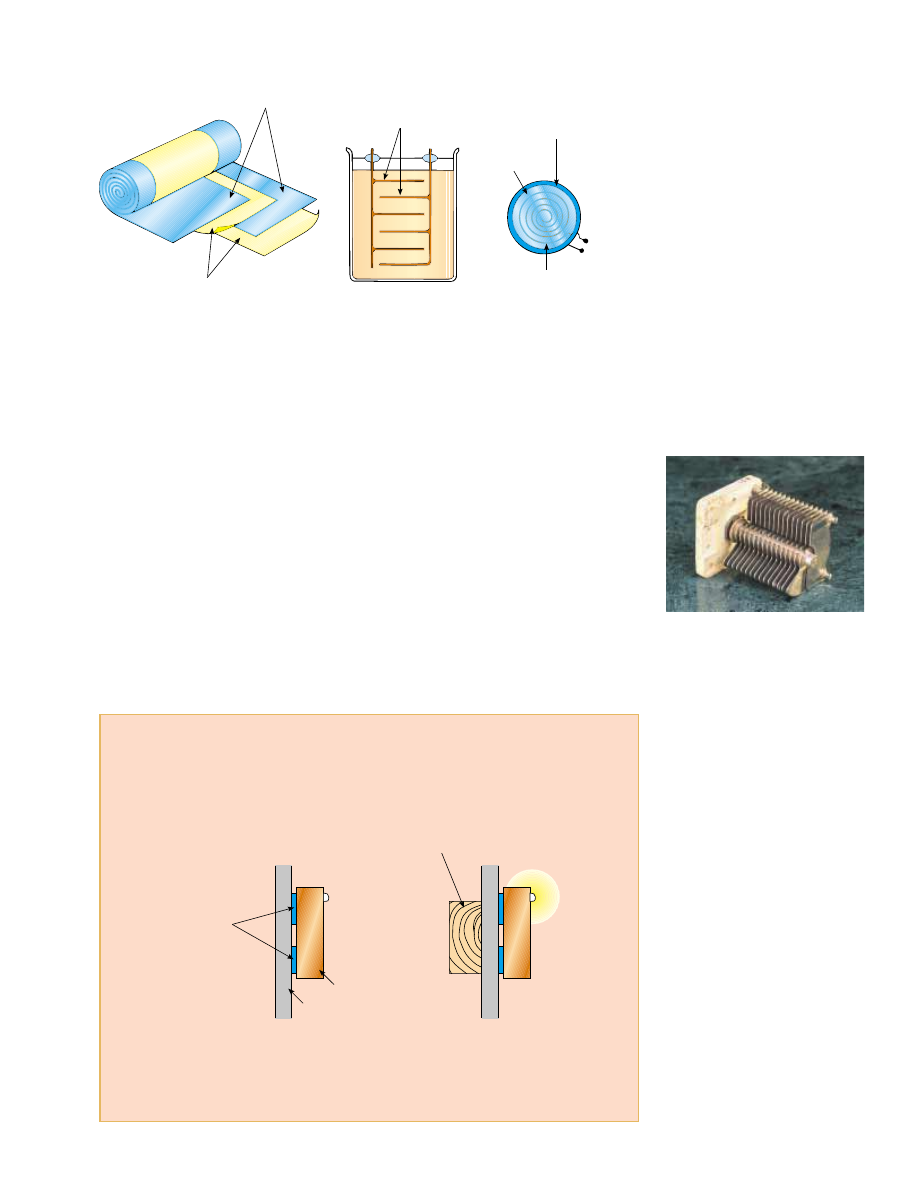
metallic plates immersed in silicone oil (Fig. 26.17b). Small capacitors are often con-
structed from ceramic materials.

Often, an electrolytic capacitor is used to store large amounts of charge at relatively low

voltages. This device, shown in Figure 26.17c, consists of a metallic foil in contact with
an  electrolyte—a  solution  that  conducts  electricity  by  virtue  of  the  motion  of  ions  con-
tained in the solution. When a voltage is applied between the foil and the electrolyte, a
thin layer of metal oxide (an insulator) is formed on the foil, and this layer serves as the
dielectric. Very large values of capacitance can be obtained in an electrolytic capacitor
because the dielectric layer is very thin, and thus the plate separation is very small.

Electrolytic capacitors are not reversible as are many other capacitors—they have a

polarity, which is indicated by positive and negative signs marked on the device. When
electrolytic capacitors are used in circuits, the polarity must be aligned properly. If the
polarity  of  the  applied  voltage  is  opposite  that  which  is  intended,  the  oxide  layer  is
removed and the capacitor conducts electricity instead of storing charge.

Variable capacitors (typically 10 to 500 pF) usually consist of two interwoven sets of

metallic plates, one fixed and the other movable, and contain air as the dielectric (Fig.
26.18). These types of capacitors are often used in radio tuning circuits.

SECTION 26.5 •  Capacitors with Dielectrics

813

Metal foil

Paper

Plates

Oil

Electrolyte

Case

Metallic foil + oxide layer

Contacts

(a)

(b)

(c)

Figure 26.17 Three commercial capacitor designs. (a) A tubular capacitor, whose plates

are separated by paper and then rolled into a cylinder. (b) A high-voltage capacitor

consisting of many parallel plates separated by insulating oil. (c) An electrolytic capacitor.

Figure 26.18 A variable capacitor.

When one set of metal plates is

rotated so as to lie between a fixed

set of plates, the capacitance of the

device changes.

George Semple

Quick Quiz 26.8

If you have ever tried to hang a picture or a mirror, you

know it can be difficult to locate a wooden stud in which to anchor your nail or screw.
A  carpenter’s  stud-finder  is  basically  a  capacitor  with  its  plates  arranged  side  by  side
instead of facing one another, as shown in Figure 26.19. When the device is moved over
a stud, does the capacitance increase or decrease?

Capacitor

plates

Stud-finder

Wall board

Stud

(b)

(a)

Figure 26.19 (Quick Quiz 26.8) A stud-finder. (a) The materials between the plates of

the capacitor are the wallboard and air. (b) When the capacitor moves across a stud in

the wall, the materials between the plates are the wallboard and the wood. The change

in the dielectric constant causes a signal light to illuminate.

814

C H A P T E R   2 6 •  Capacitance and Dielectrics

Quick  Quiz  26.9

A  fully  charged  parallel-plate  capacitor  remains  con-

nected  to  a  battery  while  you  slide  a  dielectric  between  the  plates.  Do  the  following
quantities increase, decrease, or stay the same? (a) ; (b) ; (c) between the plates;
(d) !V.

Example 26.6 A Paper-Filled Capacitor

A parallel-plate capacitor has plates of dimensions 2.0 cm by
3.0 cm separated by a 1.0-mm thickness of paper.

(A)

Find its capacitance.

Solution Because 1 # 3.7 for paper (see Table 26.1), we have

(B)

What is the maximum charge that can be placed on the

capacitor?

20 pF

#

20 * 10

$

12 

F #

 # 3.7 

$

(8.85 * 10

$

12 

C

2

/N+m

2

)(6.0 * 10

$


m

2

)

1.0 * 10

$

3


m

%

# 1 


)

0

A

d

Solution From  Table  26.1  we  see  that  the  dielectric
strength of paper is 16 * 10

6

V/m. Because the thickness of

the  paper  is  1.0 mm,  the  maximum  voltage  that  can  be
applied before breakdown is

Hence, the maximum charge is

0.32 %C

#

Q


max

#

C 


!

V

max

#

(20 * 10

$

12 

F


)(16 * 10

V


)

 # 16 * 10

3

 V

V

max

#

E

max


# (16 * 10

6

 V/m)(1.0 * 10

$

3

 m)

Example 26.7 Energy Stored Before and After

A  parallel-plate  capacitor  is  charged  with  a  battery  to  a
charge  Q

0

,  as  shown  in  Figure  26.20a.  The  battery  is  then

removed,  and  a  slab  of  material  that  has  a  dielectric
constant 1 is inserted between the plates, as shown in Figure
26.20b. Find the energy stored in the capacitor before and
after the dielectric is inserted.

Solution From Equation 26.11, we see that the energy stored
in the absence of the dielectric is

After the battery is removed and the dielectric inserted, the
charge on the capacitor remains the same. Hence,  the  energy
stored in the presence of the dielectric is

But  the  capacitance  in  the  presence  of  the  dielectric  is
# 1C

0

, so becomes

Because  1 , 1,  the  final  energy  is  less  than  the  initial
energy. We can account for the “missing’’ energy by noting
that  the  dielectric,  when  inserted,  is  pulled  into  the
device (see Section 26.7). An external agent must do neg-
ative  work  to  keep  the  dielectric  from  accelerating.  This
work  is  simply  the  difference  U

0

.  (Alternatively,  the

positive work done by the system on the external agent is
U

0

$

U.)

U

0

1

#

Q


0

2

21C


0

#

#

Q


0

2

2C


Q


0

2

2C


0

U

0

#

+

Q

0

C

0

V

0

(a)

Dielectric

+

Q

0

(b)

Figure 26.20 (Example 26.7) (a) A battery charges up a paral-

lel-plate capacitor. (b) The battery is removed and a slab of di-

electric material is inserted between the plates.

26.6 Electric Dipole in an Electric Field

We have discussed the effect on the capacitance of placing a dielectric between the plates
of  a  capacitor.  In  Section  26.7,  we  shall  describe  the  microscopic  origin  of  this  effect.
Before  we  can  do  so,  however,  we  need  to  expand  upon  the  discussion  of  the  electric
dipole that we began in Section 23.4 (see Example 23.6). The electric dipole consists of
two charges of equal magnitude and opposite sign separated by a distance 2a, as shown in
Figure 26.21. The 

electric dipole moment of this configuration is defined as the vector p

directed from $toward &along the line joining the charges and having magnitude
2aq :

(26.16)

Now  suppose  that  an  electric  dipole  is  placed  in  a  uniform  electric  field 

E,  as

shown in Figure 26.22. We identify 

E as the field external to the dipole, distinguishing it

from  the  field  due to the  dipole,  which  we  discussed  in  Section  23.4.  The  field 

E is

established by some other charge distribution, and we place the dipole into this field.
Let us imagine that the dipole moment makes an angle 2 with the field.

The electric forces acting on the two charges are equal in magnitude (qE ) and

opposite  in  direction  as  shown  in  Figure  26.22.  Thus,  the  net  force  on  the  dipole  is
zero.  However,  the  two  forces  produce  a  net  torque  on  the  dipole;  as  a  result,  the
dipole  rotates  in  the  direction  that  brings  the  dipole  moment  vector  into  greater
alignment with the field. The torque due to the force on the positive charge about an
axis through in Figure 26.22 has magnitude Fa sin 2, where sin 2 is the moment
arm of about O. This force tends to produce a clockwise rotation. The torque about
on the negative charge is also of magnitude Fa sin 2; here again, the force tends to
produce a clockwise rotation. Thus, the magnitude of the net torque about is

Because qE and # 2aq, we can express 3 as

(26.17)

It is convenient to express the torque in vector form as the cross product of the vectors
p and E:

(26.18)

We can determine the potential energy of the system—an electric dipole in an exter-

nal electric field—as a function of the orientation of the dipole with respect to the field.
To do this, we recognize that work must be done by an external agent to rotate the dipole
through an angle so as to cause the dipole moment vector to become less aligned with the
field.  The  work  done  is  then  stored  as  potential  energy  in  the  system.  The  work  dW
required  to  rotate  the  dipole  through  an  angle  d2 is  dW # 3 d2 (Eq.  10.22).  Because
3 #

pE sin 2 and because the work results in an increase in the potential energy U, we find

that for a rotation from 2

i

to 2

f

the change in potential energy of the system is

The term that contains cos 2

i

is a constant that depends on the initial orientation of

the  dipole.  It  is  convenient  for  us  to  choose  a  reference  angle  of  2

i

#

90°,  so  that

cos 2

i

#

cos 90° # 0. Furthermore, let us choose U

i

#

0 at 2

i

#

90° as our reference

of potential energy. Hence, we can express a general value of U

f

as

(26.19)

We can write this expression for the potential energy of a dipole in an electric field as
the dot product of the vectors 

p and E:

# $pE cos 2

#

pE


[$cos 2]

2

i

2

f

#

pE(cos 2

i

$

cos 2

f


)

U

f

$

U

i

#

"

2

f

2

i


3

 d2 #

"

2

f

2

i

pE


 sin 2


d2 # pE

"

2

f

2

i

sin 2 d2

$ "

p % E

3 #

2aqE


 sin 2 # p4 sin 2

3 #

2Fa sin 2

p 

! 2aq

SECTION 26.6 •  Electric Dipole in an Electric Field

815

q

– q

2a

p

+

Figure 26.21 An electric dipole

consists of two charges of equal

magnitude and opposite sign

separated by a distance of 2a. The

electric dipole moment is

directed from $ toward & q.

q

θ

– q

F

E

 F

O

+

Figure 26.22 An electric dipole in

a uniform external electric field.

The dipole moment is at an

angle 

2

to the field, causing the

dipole to experience a torque.

Torque on an electric dipole in

an external electric field

(26.20)

To  develop  a  conceptual  understanding  of  Equation  26.19,  compare  this  expres-

sion with the expression for the potential energy of the system of an object in the gravi-
tational  field  of  the  Earth,  mgh (see  Chapter  8).  The  gravitational  expression
includes  a  parameter  associated  with  the  object  we  place  in  the  field—its  mass  m.
Likewise,  Equation  26.19  includes  a  parameter  of  the  object  in  the  electric  field—its
dipole moment p. The gravitational expression includes the magnitude of the gravita-
tional field g. Similarly, Equation 26.19 includes the magnitude of the electric field E.
So far, these two contributions to the potential energy expressions appear analogous.
However, the final contribution is somewhat different in the two cases. In the gravita-
tional expression, the potential energy depends on how high we lift the object, mea-
sured by h. In Equation 26.19, the potential energy depends on the angle 2 through
which we rotate the dipole. In both cases, we are making a change in the configuration
of the system. In the gravitational case, the change involves moving an object in a trans-
lational 
sense, whereas in the electrical case, the change involves moving an object in a
rotational sense. In both cases, however, once the change is made, the system tends to
return to the original configuration when the object is released: the object of mass m
falls back to the ground, and the dipole begins to rotate back toward the configuration
in which it is aligned with the field. Thus, apart from the type of motion, the expres-
sions for potential energy in these two cases are similar.

Molecules  are  said  to  be  polarized when  a  separation  exists  between  the  average

position of the negative charges and the average position of the positive charges in the
molecule.  In  some  molecules,  such  as  water,  this  condition  is  always  present—such
molecules  are  called 

polar molecules. Molecules  that  do  not  possess  a  permanent

polarization are called 

nonpolar molecules.

We can understand the permanent polarization of water by inspecting the geome-

try  of  the  water  molecule.  In  the  water  molecule,  the  oxygen  atom  is  bonded  to  the
hydrogen  atoms  such  that  an  angle  of  105° is  formed  between  the  two  bonds  (Fig.
26.23).  The  center  of  the  negative  charge  distribution  is  near  the  oxygen  atom,  and
the  center  of  the  positive  charge  distribution  lies  at  a  point  midway  along  the  line
joining  the  hydrogen  atoms  (the  point  labeled * in  Fig.  26.23).  We  can  model  the
water molecule and other polar molecules as dipoles because the average positions of
the  positive  and  negative  charges  act  as  point  charges.  As  a  result,  we  can  apply  our
discussion of dipoles to the behavior of polar molecules.

Microwave ovens take advantage of the polar nature of the water molecule. When

in  operation,  microwave  ovens  generate  a  rapidly  changing  electric  field  that  causes
the  polar  molecules  to  swing  back  and  forth,  absorbing  energy  from  the  field  in  the
process. Because the jostling molecules collide with each other, the energy they absorb
from  the  field  is  converted  to  internal  energy,  which  corresponds  to  an  increase  in
temperature of the food.

Another  household  scenario  in  which  the  dipole  structure  of  water  is  exploited  is

washing with soap and water. Grease and oil are made up of nonpolar molecules, which
are generally not attracted to water. Plain water is not very useful for removing this type of
grime. Soap contains long molecules called surfactants. In a long molecule, the polarity
characteristics of one end of the molecule can be different from those at the other end.
In a surfactant molecule, one end acts like a nonpolar molecule and the other acts like a
polar molecule. The nonpolar end can attach to a grease or oil molecule, and the polar
end can attach to a water molecule. Thus, the soap serves as a chain, linking the dirt and
water molecules together. When the water is rinsed away, the grease and oil go with it.

A symmetric molecule (Fig. 26.24a) has no permanent polarization, but polariza-

tion can be induced by placing the molecule in an electric field. A field directed to the
left, as shown in Figure 26.24b, would cause the center of the positive charge distribu-
tion to shift to the left from its initial position and the center of the negative charge
distribution to shift to the right. This induced polarization is the effect that predominates
in most materials used as dielectrics in capacitors.

# $

p+E

816

C H A P T E R   2 6 •  Capacitance and Dielectrics

O

H

H

105

°

−−

+

+

*

Figure 26.23 The water molecule,

H

2

O, has a permanent polarization

resulting from its nonlinear

geometry. The center of the

positive charge distribution is at

the point *.

E

(a)

(b)

+

+

+

+

Figure 26.24 (a) A linear symmet-

ric molecule has no permanent

polarization. (b) An external

electric field induces a polarization

in the molecule.

Potential energy of the system

of an electric dipole in an

external electric field


Content   ..  202  203  204  205   ..