BMW AG Motorcycle (K1100LT, K1100RS). Manual - part 12
 

  Index      Manuals     BMW AG Motorcycle (K1100LT, K1100RS). Repair Manual


Search            


Content   ..  10  11  12  13   ..


BMW AG Motorcycle (K1100LT, K1100RS). Manual - part 12


12.13

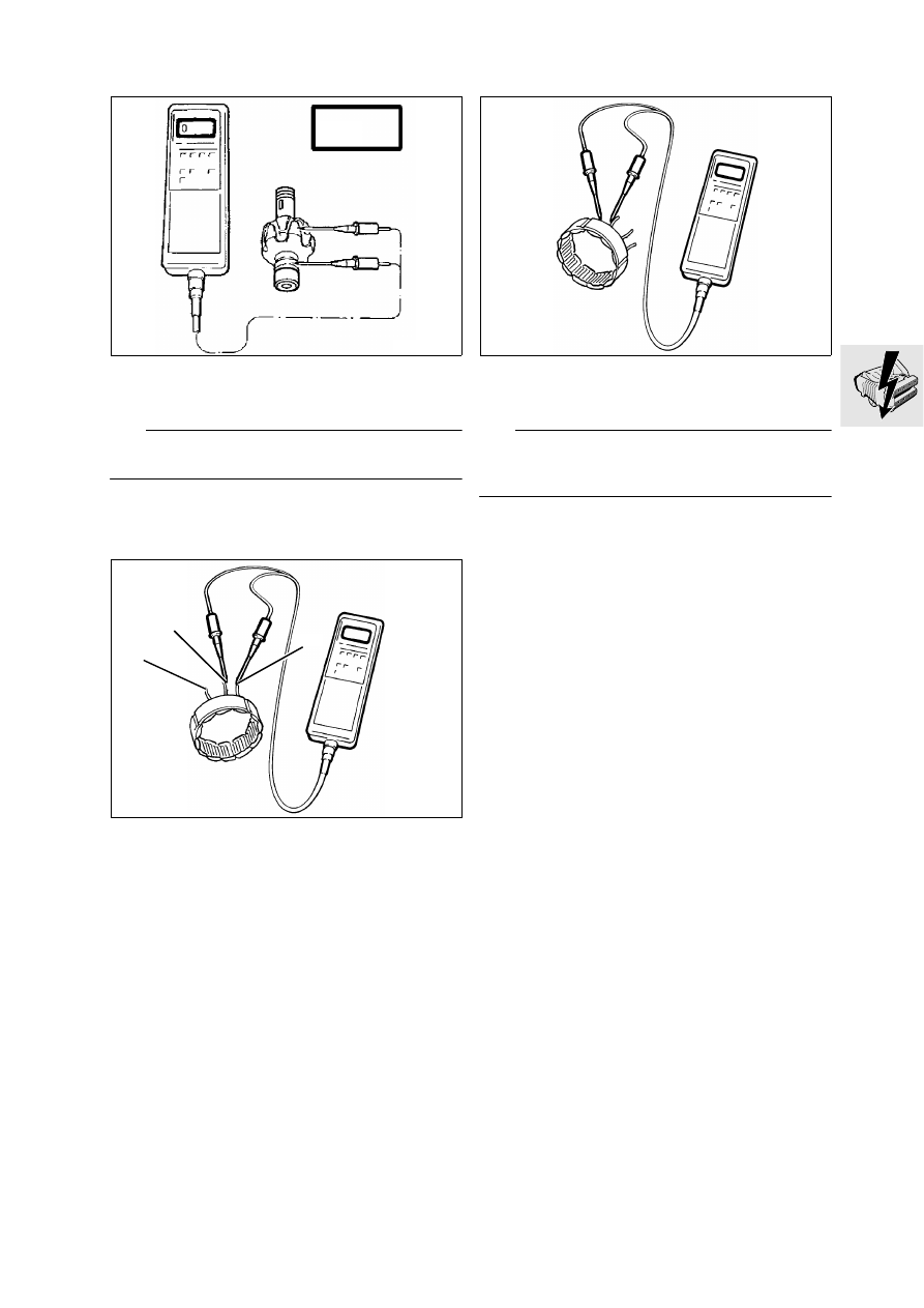
Checking armature for short to earth

Measure resistance between slip rings and ar-
mature.

L

 Note:

The resistance must be infinitely large.

Measurement result:

...................... OL = open line

Checking resistance between phase outputs

Check resistance between each pair of outputs.

1 – 2
1 – 3
2 – 3

Nominal resistance: . . . . . . . . . . . . . . . . . . . . . .0,6 

The winding is in perfect working order at measured 
values below 1.0 

Checking stator winding for short to earth

Check winding outputs individually with respect 
to earth.

L

 Note:

The resistance must be infinitely large.
Measurement result: OL = open line.

LT120120

OL

LT120130

1

2

3

LT120140

12.14

Alternator 
[LT from 1992 model year on, RS]

Remove fastening screws (1) from cover.

Release clips (2) and take off cover.

Remove voltage regulator (3)

.

Remove coupling housing (4), using counter-
holder, BMW No. 12 4 600

Assemble in the reverse order of work.

Tightening torque:

Coupling housing

......................................... 50 Nm

LT120220

2

3

1

LT120090

4

12 4 600

12.15

Checking alternator

L

 Note:

Before measuring the resistance with the BMW di-
agnostic tester, this must be zeroed:
Connect the positive (yellow) and negative (green) 
leads. 
Press the 

 key until the digital display shows 

0.00

Ω.

Using BMW diagnostic tester, 
BMW No. 61 1 510,  measure the resistance be-
tween the sliprings.

Measured result:  . . . . . . . . . . . . . . . . . . . . . . .3 

Checking armature for short to earth

Measure resistance between sliprings and arma-
ture.

Measured result: . . . . . . . . . . . . . . . 

OL = open line

61 1 510

RS120070

61 1 510

RS120060

OL

12.16

Removing and installing starter

Remove control unit.

[ABS I] 

Remove control unit.

[ABS II] 

Drain front and rear brake systems.

[ABS II] 

Remove pressure modulator.

Remove battery.

[ABS II] 

Take off battery carrier.

Release earth (ground) connection (1) at starter.

Release positive lead at starter.

Release second retaining screw (3).

Pull out starter towards rear.

Install in the reverse order of removal.

L

 Note:

[ABS II] 

Refill the front and rear brake systems.

Tightening torques:

Starter to transmission

................................... 9 Nm

Positive lead to starter

.................................... 5 Nm

LT120150

2

3

1

12.17

Disassembling and assembling starter

Clamp starter at retaining lugs in 
vice with jaw guards.

Release retaining bolts (1).

Detach bearing cap (2).

Check seal (3) and O-ring (4).

Pull out armature (5).

Note spacer washer (6)

Check O-ring (10).

LT120160

2

3

4

5

6

1

12.18

Removing and installing brush holder

1.

Hexagon nut

2.

Outer insulator

3.

Carbon brush holder

4.

Brush retaining plate

5.

O-ring

6.

Inner insulator 

LT120170

5

1

4

3

6

2

12.19

Renewing carbon


brushes

With the aid of a small screwdriver, lift spring (1) 
and pull out carbon brush.

L

 Note:

Fit carbon brush so that the chamfered side (arrow) 
faces towards the spring.

LT120180

1

12.20

Checking starter

Connect voltmeter between positive and nega-
tive pole of battery.

Operate starter for 2...3 seconds.

Read off value.

L

 Note:

If the read-off value is below 8 Volt, this indicates the 
battery does not have its full capacity.
Note down value if measured value is above 8 Volt.

Connect voltmeter between positive and nega-
tive lead at starter.

Operate starter for 2...3 seconds.

Read off measured value and compare with the 
value noted down.

L

 Note:

The starter is defective if the difference between the 
two values is greater than 0.5 Volt.

LT120190


Content   ..  10  11  12  13   ..