BMW AG Motorcycle (K1100LT, K1100RS). Manual - part 10
 

  Index      Manuals     BMW AG Motorcycle (K1100LT, K1100RS). Repair Manual


Search            


Content   ..  8  9  10  11   ..


BMW AG Motorcycle (K1100LT, K1100RS). Manual - part 10


11.49

Installing cylinder head cover

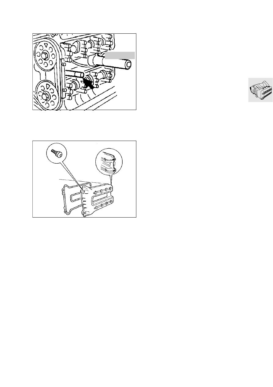
Insert reamed bolt (arrow), BMW No. 11 1 980
into inner front hole.

Press centering pin, BMW No. 00 5 500, into 
mount under the third camshaft bearing.

Install the cylinder head cover gasket with the 
half-moon cutouts first. The marks at the front 
and rear of the gasket and the cylinder head cov-
er must coincide.

Oil the gasket and half-moons lightly.

Press in the half-moon on the gearbox side first.

Apply a small amount of 3-Bond 1209 to the joint 
area of the cylinder head and timing case cover.

Attach the cylinder head cover with gasket.

Insert all retaining screws as far as possible.

Tighten the retaining screws in a crosswise pat-
tern, working from the inside outwards.

Tightening torque:

Cylinder head cover ....................................... 8 Nm

Take out the reamed and centering screw and in-
sert the remaining retaining screws.

LT110720

11 1 990

LT110730

11.50

Installing engine

Attach hoist, BMW No. 00 1 510, to the oil sump.

Set the engine down on the hoist platform.

Release the engine mounting at the engine 
block.

Install the throttle rail.

Install the inner bulkhead at the cylinder (3).

Install the lower section of the air cleaner hous-
ing.

Install the fuel return line with pressure regulator.

Connect the crankcase breather.

Position the frame with telescopic fork and frame 
support over the engine.

Bolt the engine and driveline together.

Tightening torque:

Gearbox to intermediate flange .................... 16 Nm

Bolt the engine and frame together in the order 
stated here:

1. Insert all 5 bolts loosely but do not screw them 

fully in. Insert a 1 mm thick spacing washer at the 
front right, between the cylinder head and frame 
strut, and a support washer on the inside.

2. Tighten bolts 1, 4 and 3.
3. Shim to the correct thickness at the front left and 

install the support washer on the outside, then 
tighten the bolt.

4. Shim the attachment point at the intermediate 

flange and tighten the bolt.

Tightening torque:

Frame to engine ........................................... 45 Nm

Install fuel injection rail.

Tightening torque:

Fuel injection rail ............................................ 7 Nm

1

2

3

4

5

LT110750

11.51

Connect the engine wiring harness (coolant stub 
pipe, throttle position sensor, CO detector, injec-
tors, air cleaner housing).

Attach cable straps (three) at fuel injection rail.

Attach wire cables for increased idle speed and 
throttle operation.

Throttle cable play....................... 0.75 mm (0.03 in)

Install the radiator.

Install the left engine bulkhead (1).

Attach cable strap (2).

Install fuel line (3).

Install right engine bulkhead (4).

Attach cable strap (5).

Install coolant line (6) in bulkhead.

Install driveline.

Install fuel tank.

Install radiator surround.

Install left and right side sections.

Install storage compartment.

Install knee pads.

1

2

3

LT110770

4

5

6

LT110780

11.52

Checking/adjusting valve clear-
ances

e

 Caution:

Never unscrew the spark plugs before measuring 
valve clearances. Particles of oily soot could be-
come lodged behind an exhaust valve head and fal-
sify the measurement.

Remove left side section of fairing.

Remove the cylinder head cover.

Remove cover for Hall-effect transmitter.

Turn the engine only at the crankshaft (direction 
of rotation: anti-clockwise).

Measure valve clearance with feeler gauge.

Max. engine temperature 35 °C.

Determine size of replacement tappets by com-
paring desired and actual measurements.

Valve clearances:
Inlet ..................... 0.15…0.20 mm (0.006…0.008 in)
Exhaust ............... 0.25…0.30 mm (0.010…0.012 in)

Adjusting valve clearances

The camshaft must be removed before the buck-
et tappets can be renewed.

Set cylinder 1 (timing end) to top dead centre on 
the ignition stroke.

The adjusting device for the camshafts,
BMW No. 11 3 700, must enter the slots at the 
end of the shafts.

Remove the screw plug in the timing case cover.

Hold the chain tensioner and timing chain with 
eccentric tensioner, BMW No. 11 2 640.

Pull back tensioning pin (1) and screw in eccen-
tric (2) by 3…4 turns.

Push the tensioning pin forward above the timing 
chain.

Turn the eccentric slightly to the right to locate 
the timing chain and chain tensioner.

Secure the eccentric with locknut (3).

Remove the chain sprockets.

Remove the camshafts.

Renew the bucket tappets as necessary.

Assemble in the reverse order of work.

11 3 700

LT110800

1

2

3

LT110800

12.1

Contents

Page

12

Technical data

................................................................................................................................ 3

Removing and installing Hall generator 

...........................................................................5

Adjusting ignition timing 

...........................................................................................................6

Removing and installing ignition coils 

..............................................................................8

Removing and installing ignition output stage 

............................................................9

Removing and installing alternator 

..................................................................................10

Disassembling and assembling alternator 

...................................................................11

Alternator 
[only LT up to 1992 model year]

 .............................................................................................11

Checking exciter winding  ..................................................................................................................12
Checking armature for short to earth .................................................................................................13
Checking resistance between phase outputs  ....................................................................................13
Checking stator winding for short to earth .........................................................................................13

Alternator 
[LT from 1992 model year on, RS]

 ........................................................................................14

Checking alternator  ...........................................................................................................................15
Checking armature for short to earth .................................................................................................15

Removing and installing starter 

.........................................................................................16

Disassembling and assembling starter

 ...............................................................................17

Removing and installing brush holder ................................................................................................18
Renewing carbon brushes .................................................................................................................19

Checking starter 

.........................................................................................................................20

Checking starter relay

 .................................................................................................................21

Checking starter relay with ohmmeter  ...............................................................................................21

Troubleshooting 

..........................................................................................................................22

Troubleshooting on alternator

 .................................................................................................22

Troubleshooting on starter

 .......................................................................................................26

Troubleshooting on battery

 ......................................................................................................29

12 Engine electrics

12.2

12.3

12

Technical data

K 1100 LT

K 1100 RS

Starter

Type

Permanent magnet motor

Gear ratio

27 : 1

Output

kW 0,7

Alternator

Type 

Three-phase alternator with integrated fully elec-
tronic regulator

Drive

direct, gear ratio 1 : 1.5

Maximum output

W/V 460/14 / – 700/14 from Mod.93

Max. current

A 33/ – 50 Mod.93

Charge cut-in

rpm 950 ± 50

Max. speed

rpm 12 300/ – 20 00 from Mod.93

Spark plugs

Bosch

XR 5 DC

Beru

12R-5 DU

Electrode gap

mm (in) 0.6 (0.2362) + 0.1(0.0039), 

wear limit 

0,9 (0.0354)

Thread

metric

M 12 x 1.25

Ignition

Ignition system

Motronic (mapped ignition timing control)

Ignition pulse triggert

Two magnetic barriers (Hall generator) secured 
on the 

crankshaf

Ignition timing adjustment, static

°KW 6 vor OT= 0,24 mm (0,00945 in)

Max. advanced ignition

°KW 31

Max. ignition control

°KW 25

Control start

rpm 1 500

Control end

rpm 8 650

Speed limitation

rpm 8 980

Ignition coil

Double ignition coil, make Bosch

Resistance:

primary

~ 0,5

secondary

k

~ 13

12.4


Content   ..  8  9  10  11   ..