BMW AG Motorcycle (K1100LT, K1100RS). Manual - part 11
 

  Index      Manuals     BMW AG Motorcycle (K1100LT, K1100RS). Repair Manual


Search            


Content   ..  9  10  11  12   ..


BMW AG Motorcycle (K1100LT, K1100RS). Manual - part 11


12.5

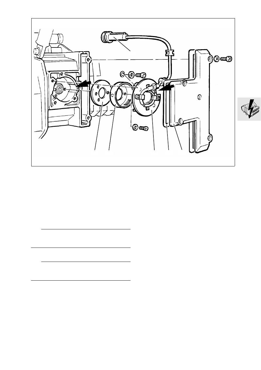
Removing and installing Hall gener-
ator

Disconnect ground lead of battery and insulate.

Remove radiator cowling.

Remove fuel tank.

Disconnect Hall generator (1) plug connection.

Remove cover (2) together with gasket (3).

Remove base plate (4).

Remove rotor (5) and setting plate (6).

L

 Note:

Mark installation position of setting plate on engine 
case, or remove in TDC position.

Install in the reverse order of removal.

L

 Note:

The recess on the engine case and on the base 
plate must be aligned flush.

Tightening torques:

Base plate ................................................... 3.5 Nm
Cover ............................................................. 9 Nm

LT120010

6

1

5

4

3

2

12.6

Adjusting ignition timing

Remove radiator cowling.

Remove bottom left fairing.

Remove fuel tank.

Disconnect plug connection on Hall generator 
lead under the fuel tank.

Connect adapter lead (2), BMW  No. 12 3 651, to 
Hall generator lead.

Connect ignition setting device (3), 
BMW No. 12 3 650,to adapter line.

Disconnect spark plug connector with flat-nose 
pliers.

Unscrew spark plugs with spark plug box span-
ner, BMW No. 12 3 500.

Screw dial gauge with extension (1), 
BMW No. 00 2 580, into cylinder No. 1.

Set piston to TDC.

Set scale ring of dial gauge to 0.

Turn engine back in clockwise direction until pis-
ton setting ignition point is reached.

Ignition point:
6 ° before TDC = 0.24 mm (0.00945 in) before TDC

LT120020

2

1

3

12 3 650

12 3 651

12 3 650

00 2 580

LT120030

12.7

Loosen base plate (1) and turn to the left or right 
until diode (2) on ignition setting device goes out.

L

 Note:

Ignition timing adjustment
Turn to left

Retard ignition

Turn to right

Advance ignition

Firmly tighten base plate.

Check ignition timing:
Crank engine in normal direction. The diode on 
the ignition setting device must go out at piston 
position 0.24 (0.00945 in) mm before TDC.

Tightening torques:

Base plate ................................................... 3.5 Nm
Cover ............................................................. 9 Nm
Spark plug.................................................... 20 Nm

12 3 650

LT120040

1

2

12.8

Removing and installing ignition 
coils

Disconnect earth (ground) lead of battery and in-
sulate.

Remove top (1) and bottom (2) ignition coil cover.

Disconnect plug connector (3) at the ignition 
coils.

Disconnect plug connector (4) for terminal “1” 
and “15”.

Release earth (ground) connection (5) on starter.

Release top and bottom mounting at intermedi-
ate flange (6).

Install in the reverse order of removal.

L

 Note:

Note assignment of ignition leads to ignition coil. Ig-
nition coils are also marked.

Tightening torque:

Ignition coils to intermediate flange ................ 5 Nm

LT120050

1

4

6

2

3

5

12.9

Removing and installing ignition 
output stage

Remove left battery bracket.

Disconnect earth (ground) lead of battery.

Remove ignition coils.

Remove ignition output stage (1).

Press retaining clip (2) and detach ignition output 
stage.

Install in the reverse order of removal.

L

 Note:

Before installing the ignition output stage, coat the 
rear with heat conducting paste Curil K 2.

LT120060

3

2

1

12.10

Removing and installing alternator

Remove right battery panel.

Remove Motronic control unit.

[ABS I] Remove ABS control unit.

Remove battery.

Remove cover (1).

Disconnect plug (2).

Remove alternator.

Install in the reverse order of removal.

Tightening torque:

Alternator ...................................................... 22 Nm

LT120070

1

2

12.11

Disassembling and assembling 
alternator

Alternator


[only LT up to 1992 model year]

Remove damper elements (1)

Remove coupling housing (2) with holding tool 
(3), BMW No. 12 4 600.

Pull off fan wheel (4).

Remove key (5).

Release retaining screw (6) for bearing end plate.

Clamp alternator in vice with jaw guards.

Remove bearing end plate (7) with three-point 
puller, BMW No. 33 1 830.

Tightening torque:

Coupling housing...........................................50 Nm

LT120080

5

7

6

4

2

1

12 4 600

LT120090

2

3

12.12

Remove regulator (8) with carbon brushes.

Carefully lift out armature (9) together with bear-
ing (10).

Remove bearing (10) from armature shaft.

Unsolder stator (11) on diode plate (12); mark the 
wires.

Remove diode plate.

Remove O-ring (14).

Install in the reverse order of removal.

L

 Note:

During assembly, insulate the solder points on the 
diode plate with silicone. Coat bearing seat in hous-
ing with Molykote paste.

Checking exciter winding

Using the test probes of the BMW diagnosis test-
er, 

BMW No. 61 1 510

, measure the resistance 

across the slip rings.

Nominal resistance.......................................7 ± 1


LT120100

9

11

10

14

13

8

12

61 1 510

LT120110


Content   ..  9  10  11  12   ..