Kawasaki Ninja 650R, ER-6f, ER-6f ABS Motorcycle. Service Manual (2009-2011 year) - page 16
 

  Index      Manuals     Kawasaki Ninja 650R, ER-6f, ER-6f ABS Motorcycle. Service Manual (2009-2011 year)


Search            copyright infringement  


Content      ..     14      15      16      17     ..


Kawasaki Ninja 650R, ER-6f, ER-6f ABS Motorcycle. Service Manual (2009-2011 year) - page 16


ELECTRICAL SYSTEM 16-11

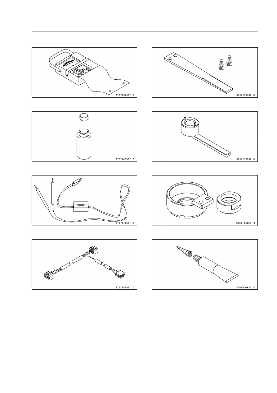
Special Tools and Sealant

Hand Tester:
57001-1394

Flywheel Puller Assembly, M38 × 1.5/M35 × 1.5:
57001-1405

Peak Voltage Adapter:
57001-1415

Lead Wire - Peak Voltage Adapter:
57001-1449

Grip:
57001-1591

Rotor Holder:
57001-1567

Rotor Holder:
57001-1658

Kawasaki Bond (Silicone Sealant):
92104-0004

16-12 ELECTRICAL SYSTEM

Parts Location

ELECTRICAL SYSTEM 16-13

Parts Location

1. Air Switching Valve
2. Alternator
3. Battery 12 V 10 Ah
4. Crankshaft Sensor
5. ECU
6. Radiator Fan Motor
7. Front Brake Light Switch
8. Fuse Box with ECU Main Fuse
9. Ignition Switch

10. Meter Unit

11. Neutral Switch

12. Oil Pressure Switch
13. Rear Brake Light Switch
14. Regulator/Rectifier
15. Relay Box
16. Sidestand Switch
17. Speed Sensor
18. Starter Lockout Switch
19. Starter Motor
20. Starter Relay with Main Fuse
21. Stick Coils
22. Turn Signal Relay
23. Water Temperature Sensor
24. Oxygen Sensor (Equipped Models)

16-14 ELECTRICAL SYSTEM

Wiring Diagram (Other than US, CA and CAL Models)

ELECTRICAL SYSTEM 16-15

Wiring Diagram (Other than US, CA and CAL Models)

16-16 ELECTRICAL SYSTEM

Wiring Diagram (US, CA and CAL Models)

ELECTRICAL SYSTEM 16-17

Wiring Diagram (US, CA and CAL Models)

16-18 ELECTRICAL SYSTEM

Wiring Diagram (EX650D Models)

ELECTRICAL SYSTEM 16-19

Wiring Diagram (EX650D Models)

16-20 ELECTRICAL SYSTEM

Precautions

There are a number of important precautions that are

musts when servicing electrical systems. Learn and ob-
serve all the rules below.

Do not reverse the battery cable connections. This will
burn out the diodes on the electrical parts.

Always check battery condition before condemning other
parts of an electrical system. A fully charged battery is a
must for conducting accurate electrical system tests.

The electrical parts should never be struck sharply, as
with a hammer, or allowed to fall on a hard surface. Such
a shock to the parts can damage them.

To prevent damage to electrical parts, do not disconnect
the battery cables or any other electrical connections
when the ignition switch is on, or while the engine is
running.

Because of the large amount of current, never keep the
starter button pushed when the starter motor will not turn
over, or the current may burn out the starter motor wind-
ings.

Take care not to short the cables that are directly con-
nected to the battery positive (+) terminal to the chassis
ground.

Troubles may involve one or in some cases all items.
Never replace a defective part without determining what
CAUSED the failure. If the failure was caused by some
other item or items, they must be repaired or replaced, or
the new replacement will soon fail again.

Make sure all connectors in the circuit are clean and tight,
and examine wires for signs of burning, fraying, etc. Poor
wires and bad connections will affect electrical system op-
eration.

Measure coil and winding resistance when the part is cold
(at room temperature).

ELECTRICAL SYSTEM 16-21

Electrical Wiring

Wiring Inspection

Visually inspect the wiring for signs of burning, fraying,
etc.
If any wiring is poor, replace the damaged wiring.

Pull each connector [A] apart and inspect it for corrosion,
dirt, and damage.
If the connector is corroded or dirty, clean it carefully. If it
is damaged, replace it.

Check the wiring for continuity.

Use the wiring diagram to find the ends of the lead which
is suspected of being a problem.

Connect the hand tester between the ends of the leads.

Special Tool - Hand Tester: 57001-1394

Set the tester to the × 1

range, and read the tester.

If the tester does not read 0

, the lead is defective. Re-

place the lead or the wiring harness [B] if necessary.

16-22 ELECTRICAL SYSTEM

Battery

Battery Removal

Turn off the ignition switch.

Remove the seat (see Seat Removal in the Frame chap-
ter).

Disconnect the negative (–) cable [A].

CAUTION

Be sure to disconnect the negative (–) cable first.

Slide out the positive (+) terminal cap [B] and then discon-
nect the positive (+) cable.

Remove the battery [A].

NOTE

Run the suitable band [B] into the positive (+) terminal.

Pull up the battery with both hands.

Battery Installation

Turn off the ignition switch.

Put the battery into the battery case.

Install the positive (+) cable first.

Install the negative (–) cable [A].

Apply a little grease on the terminals to prevent corrosion.

Cover the positive (+) terminal with the cap [B].

Battery Activation

Electrolyte Filling

Make sure that the model name [A] of the electrolyte con-
tainer matches the model name [B] of the battery. These
names must be the same.

Battery Model Name for EX650C/D: FTX12-BS

CAUTION

Be sure to use the electrolyte container with the
same model name as the battery since the elec-
trolyte volume and specific gravity vary with the
battery type. This is to prevent overfilling of the
electrolyte, shorting the battery life, and deteriora-
tion of the battery performance.

ELECTRICAL SYSTEM 16-23

Battery

CAUTION

Do not remove the aluminum sealing sheet [A] from
the filler ports [B] until just prior to use. Be sure to
use the dedicated electrolyte container for correct
electrolyte volume.

Place the battery on a level surface.

Check to see that the sealing sheet has no peeling, tears,
or holes in it.

Remove the sealing sheet.

NOTE

The battery is vacuum sealed. If the sealing sheet has
leaked air into the battery, it may require a longer initial
charge.

Remove the electrolyte container from the vinyl bag.

Detach the strip of caps [A] from the container and set
aside, these will be used later to seal the battery.

NOTE

Do not pierce or otherwise open the sealed cells [B] of
the electrolyte container. Do not attempt to separate
individual cells.

Place the electrolyte container upside down with the six
sealed cells into the filler ports of the battery. Hold the
container level, push down to break the seals of all six
cells. You will see air bubbles rising into each cell as the
ports fill.

NOTE

Do not tilt the electrolyte container

Check the electrolyte flow.
If no air bubbles [A] are coming up from the filler ports, or
if the container cells have not emptied completely, tap the
container [B] a few times.

Keep the container in place for 20 minutes or more. Don’t
remove the container from the battery until it’s empty, the
battery requires all the electrolyte from the container for
proper operation.

CAUTION

Removal of the container before it is completely
empty can shorten the service life of the battery. Do
not remove the electrolyte container until it is com-
pletely empty and 20 minutes have elapsed.

16-24 ELECTRICAL SYSTEM

Battery

Gently remove the container from the battery.

Let the battery sit for 30 minutes prior to charging to allow
the electrolyte to permeate into the plates for optimum
performance.

NOTE

Charging the battery immediately after filling can
shorten service life. Let the battery sit for at least 30
minutes after filling.

Initial Charge

Place the strip [A] of caps loosely over the filler ports.

Newly activated sealed batteries require an initial charge.

Standard Charge:

1.2 A × 5

10 hours

If using a recommended battery charger, follow the
charger’s instructions for newly activated sealed battery.

Kawasaki-recommended chargers

Optimate III

Yuasa 1.5 Amp Automatic Charger

Battery Mate 150-9

If the above chargers are not available, use equivalent
one.

NOTE

Charging rates will vary depending on how long the
battery has been stored, temperature, and the type of
charger used. Let battery sit 30 minutes after initial
charge, then check voltage using a voltmeter. If it is
not at least 12.6 V, repeat charging cycle.

After charging is completed, press down firmly with both
hands to seat the strip of caps [A] into the battery (don’t
pound or hammer.). When properly installed, the strip of
the caps will be level with the top of the battery.

CAUTION

Once the strip of the caps is installed onto the bat-
tery, never remove the caps, nor add water or elec-
trolyte to the battery.

ELECTRICAL SYSTEM 16-25

Battery

NOTE

To ensure maximum battery life and customer satisfac-
tion, it is recommended the battery be load tested at
three times its amp-hour rating for 15 seconds.
Re-check voltage and if less than 12.6 V repeat the
charging cycle and load test. If still below 12.6 V the
battery is defective.

Precautions

1) No need of topping-up

No topping-up is necessary in this battery until it ends its life under normal use. Forcibly prying

off the seal cap to add water is very dangerous. Never do that.

2) Refreshing charge

If an engine will not start, a horn sounds weak, or lamps are dim, it indicates the battery has been

discharged. Give refresh charge for 5 to 10 hours with charge current shown in the specification
(see Specifications).

When a fast charge is inevitably required, do it following precisely the maximum charge current

and time conditions indicated on the battery.

CAUTION

This battery is designed to sustain no unusual deterioration if refresh-charged according
to the method specified above. However, the battery’s performance may be reduced no-
ticeably if charged under conditions other than given above. Never remove the seal cap
during refresh charge.
If by chance an excessive amount of gas is generated due to overcharging, the relief valve
releases the gas to keep the battery normal.

3) When you do not use the motorcycle for months.

Give a refresh charge before you store the motorcycle and store it with the negative cable re-

moved. Give a refresh charge once a month during storage.

4) Battery life

If the battery will not start the engine even after several refresh charges, the battery has ex-

ceeded its useful life. Replace it (Provided, however, the vehicle’s starting system has no prob-
lem).

WARNING

Keep the battery away from sparks and open flames during charging, since the battery
gives off an explosive gas mixture of hydrogen and oxygen. When using a battery charger,
connect the battery to the charger before turning on the charger.
This procedure prevents sparks at the battery terminals which could ignite any battery
gases.
No fire should be drawn near the battery, or no terminals should have the tightening loos-
ened.
The electrolyte contains sulfuric acid. Be careful not to have it touch your skin or eyes. If
touched, wash it off with liberal amount of water. Get medial attention if severe.

Interchange

A sealed battery can fully display its performance only when combined with a proper vehicle electric

system. Therefore, replace a sealed battery only on a motorcycle which was originally equipped with
a sealed battery.

Be careful, if a sealed battery is installed on a motorcycle which had an ordinary battery as original

equipment, the sealed battery’s life will be shortened.

16-26 ELECTRICAL SYSTEM

Battery

Charging Condition Inspection

Battery charging condition can be checked by measuring

battery terminal voltage with a digital voltmeter [A].

Remove the battery (see Battery Removal).

CAUTION

Be sure to disconnect the negative (−) lead first.

Measure the battery terminal voltage.

NOTE

Measure with a digital voltmeter which can be read to
one decimal place voltage.

If the reading is 12.6 V or more, no refresh charge is re-
quired, however, if the reading is below the specified, re-
fresh charge is required.

Battery Terminal Voltage

Standard: 12.6 V or more

Terminal Voltage (V) [A]
Battery Charge Rate (%) [B]
Refresh charge is required [C]
Good [D]

Refreshing Charge

Remove the battery [A] (see Battery Removal).

Refresh-charge by following method according to the bat-
tery terminal voltage.

WARNING

This battery is sealed type.

Never remove seal

sheet [B] even at charging.

Never add water.

Charge with current and time as stated below.

Terminal Voltage: 11.5

less than 12.6 V

Standard Charge

1.2 A × 5

10 h (see following chart)

Quick Charge

5.0 A × 1 h

CAUTION

If possible, do not quick charge. If the quick charge
is done unavoidably, do the standard charge later
on.

Terminal Voltage: less than 11.5 V

Charging Method:

1.2 A × 20 h

ELECTRICAL SYSTEM 16-27

Battery

NOTE

Increase the charging voltage to a maximum voltage of
25 V if the battery will not accept current initially. Charge
for no more than 5 minutes at the increased voltage then
check if the battery is drawing current. If the battery
will accept current decrease the voltage and charge by
the standard charging method described on the battery
case. If the battery will not accept current after 5 min-
utes, replace the battery.

Battery [A]
Battery Charger [B]
Standard Value [C]
Current starts to flow [D]

Determine battery condition after refreshing charge.

Determine the condition of the battery 30 minutes after
completion of the charge by measuring the terminal volt-
age according to the table below.

Criteria

Judgement

12.6 V or higher

Good

12.0

lower than 12.6 V

Charge insufficient

Recharge

lower than 12.0 V

Unserviceable

Replace

16-28 ELECTRICAL SYSTEM

Charging System

Alternator Cover Removal

Remove:

Lower Fairing (see Lower Fairing Removal in the Frame
chapter)
Frame Cover (see Frame Cover Removal in the Frame
chapter)
Engine Oil (Drain, see Engine Oil Change in the Periodic
Maintenance chapter)
Bolts [A]
Engine Sprocket Cover [B]

Disconnect the alternator lead connector [A].

Remove:

Left Upper Fairing Cover (see Upper Fairing Cover Re-
moval in the Frame chapter)
Alternator Cover Bolts [A]
Alternator Cover [B]

NOTE

Place a suitable container under the alternator cover.

Alternator Cover Installation

Apply silicone sealant to the alternator lead grommet and
crankcase halves mating surface [A].

Sealant - Kawasaki Bond (Silicone Sealant): 92104-0004

Install the dowel pins [B].

Replace the alternator cover gasket with a new one.

Install the alternator cover.

Torque - Alternator Cover Bolts: 9.8 N·m (1.0 kgf·m, 87

in·lb)

70 mm (2.8 in.) Bolt [A]
35 mm (1.4 in.) Bolts [B]
Tighten with Clamp [C]

ELECTRICAL SYSTEM 16-29

Charging System

Stator Coil Removal

Remove:

Alternator Cover (see Alternator Cover Removal)
Holding Plate Bolt [A] and Plate
Alternator Lead Grommet [B]
Stator Coil Bolts [C]

Take off the stator coil [D] from the alternator cover.

Stator Coil Installation

Apply a non-permanent locking agent to the threads of
the stator coil bolts and the holding plate bolt.

Clamp the alternator lead with a holding plate.

Install the stator coil.

Torque - Stator Coil Bolts: 12 N·m (1.2 kgf·m, 106 in·lb)

Alternator Lead Holding Plate Bolt: 9.8 N·m (1.0

kgf·m, 87 in·lb)

Apply silicone sealant to the circumference of the alter-
nator lead grommet, and fit the grommet into the notch of
the cover.

Sealant - Kawasaki Bond (Silicone Sealant): 92104-0004

Alternator Rotor Removal

Remove:

Alternator Cover (see Alternator Cover Removal)
Starter Idle Gear [A] and Shaft
Torque Limiter [B] and Shaft

Wipe oil off the circumference of the rotor.

Hold the alternator rotor steady with the rotor holder [A].

Special Tools - Grip [B]: 57001-1591

Rotor Holder: 57001-1658

Remove the rotor bolt [C] and the washer.

16-30 ELECTRICAL SYSTEM

Charging System

Using the flywheel puller [A], remove the alternator rotor
from the crankshaft.

Special Tool - Flywheel Puller Assembly, M38 × 1.5/M35 ×

1.5: 57001-1405

CAUTION

Do not attempt to strike the alternator rotor itself.
Striking the rotor can cause the magnets to lose
their magnetism.

Alternator Rotor Installation

Using a cleaning fluid, clean off any oil or dirt on the fol-
lowing portions and dry them with a clean cloth.

Crankshaft Tapered Portion [A]
Alternator Rotor Tapered Portion [B]

Apply a thin coat of molybdenum disulfide grease to the
crankshaft [C].

Install the starter clutch gear [A] and washer [B].

Again, clean the crankshaft tapered portion [C] and dry
there.

Install the alternator rotor while turning the starter clutch
gear clockwise.

Install the washer [A].

NOTE

Confirm the alternator rotor fit or not to the crankshaft
before tightening it with specified torque.

Apply molybdenum disulfide oil solution to the threads
and seating surface of the rotor bolt.

Install the rotor bolt [B] and tighten it with 70 N·m (7.0
kgf·m, 52 ft·lb) of torque.

Remove the rotor bolt and washer.

Check the tightening torque with flywheel puller.
If the rotor is not pulled out with 20 N·m (2.0 kgf·m, 15
ft·lb) of drawing torque, it is installed correctly.
If the rotor is pulled out with under 20 N·m (2.0 kgf·m, 15
ft·lb) of drawing torque, clean off any oil dirt or flaw of the
crankshaft and rotor tapered portion, and dry them with
a clean cloth. Then, confirm that it is not pulled out with
above torque.

Tighten the alternator rotor bolt while holding the alterna-
tor rotor steady with the rotor holder.

Special Tools - Grip: 57001-1591

Rotor Holder: 57001-1658

Torque - Alternator Rotor Bolt: 155 N·m (15.8 kgf·m, 114

ft·lb)

ELECTRICAL SYSTEM 16-31

Charging System

Apply a thin coat of molybdenum disulfide grease to the
shafts [A], and install them.

Install the torque limiter [B] and starter idle gear [C].

Install the alternator cover (see Alternator Cover Installa-
tion).

Alternator Inspection

There are three types of alternator failures: short, open

(wire burned out), or loss in rotor magnetism. A short or
open in one of the coil wires will result in either a low output,
or no output at all. A loss in rotor magnetism, which may be
caused by dropping or hitting the alternator, by leaving it
near an electromagnetic field, or just by aging, will result in
low output.

To check the alternator output voltage, do the following
procedures.

Turn off the ignition switch.

Remove the left frame cover (see Frame Cover Removal
in the Frame chapter).

Disconnect the alternator lead connector [A].

Connect the hand tester as shown in the table 1.

Special Tool - Hand Tester: 57001-1394

Start the engine.

Run it at the rpm given in the table 1.

Note the voltage readings (total 3 measurements).

Table 1: Alternator Output Voltage

Connections

Tester

Range

Tester (+) to

Tester (–) to

Reading

at 4 000 rpm

250 V AC

One White

lead

Another White lead 42 V or more

If the output voltage shows the value in the table, the al-
ternator operates properly.
If the output voltage shows a much lower than the value
in the table, the alternator is defective.

Check the stator coil resistance as follows.

Stop the engine.

Connect the hand tester as shown in the table 2.

Note the readings (total 3 measurement).

Table 2: Stator Coil Resistance

Connections

Tester

Range

Tester (+) to

Tester (–) to

Reading

× 1

One White

lead

Another White lead 0.18

0.27

16-32 ELECTRICAL SYSTEM

Charging System

If there is more resistance than shown in the table, or no
hand tester reading (infinity) for any two leads, the stator
has an open lead and must be replaced. Much less than
this resistance means the stator is shorted, and must be
replaced.

Using the highest resistance range of the hand tester,
measure the resistance between each of the white leads
and chassis ground.
Any hand tester reading less than infinity (

) indicates a

short, necessitating stator replacement.
If the stator coils have normal resistance, but the voltage
check showed the alternator to be defective; then the rotor
magnets have probably weakened, and the rotor must be
replaced.

Regulator/Rectifier Inspection

Remove:

Bolts [A]

Slide out the dust cover, and disconnect the connector
[A].

Remove the regulator/rectifier [B] with the bracket.

EX650D Models

Remove the muffler body (see Muffler Body Removal in
the Engine Top End chapter).

Slide out the dust cover [A], and disconnect the connector.

Remove the bolts [B], and take off the regulator/rectifier
[C].

ELECTRICAL SYSTEM 16-33

Charging System

Rectifier Circuit Check

Check conductivity of the following pair of terminals.

Rectifier Circuit Inspection

W1-BK1,

W1-BK2,

W1-BK3

Tester connection

BK/Y-BK1,

BK/Y-BK2,

BK/Y-BK3

The resistance should be low in one direction and more
than ten times as much in the other direction. If any two
leads are low or high in both directions, the rectifier is
defective and the regulator/rectifier must be replaced.

NOTE

The actual meter reading varies with the meter used
and the individual rectifier, but, generally speaking the
lower reading should be from zero to one half the scale.

Regulator Circuit Check

To test the regulator out of circuit, use three 12 V batteries

and a test light (12 V 3

6 W bulb in a socket with leads).

CAUTION

The test light works as an indicator and also a cur-
rent limiter to protect the regulator/rectifier from ex-
cessive current. Do not use an ammeter instead of
a test light.

Check to be sure the rectifier circuit is normal before con-
tinuing.

Do the 1st step regulator circuit test.

Connect the test light and the 12 V battery to the regula-
tor/rectifier as shown.

Check the BK1, BK2 and BK3 terminal respectively.
If the test light turns on, the regulator/rectifier is defective.
Replace it.
If the test light does not turn on, continue the test.

Do the 2nd step regulator circuit test.

Connect the test light and the 12 V battery in the same
manner as specified in the “Regulator Circuit Test-1st
Step”.

Apply 12 V to the voltage W2 terminal.

Check the BK1, BK2 and BK3 terminal respectively.
If the test light turns on, the regulator/rectifier is defective.
Replace it.
If the test light does not turn on, continue the test.

16-34 ELECTRICAL SYSTEM

Charging System

Do the 3rd step regulator circuit test.

Connect the test light and the 12 V battery in the same
manner as specified in the “Regulator Circuit Test-1st
Step”.

Momentarily apply 24 V to the voltage W2 terminal by
adding a 12 V battery.

Check the BK1, BK2 and BK3 terminals respectively.

CAUTION

Do not apply more than 24 V. If more than 24 V is ap-
plied, the regulator/rectifier may be damaged. Do
not apply 24 V more than a few seconds. If 24 V
is applied for more than a few seconds, the regula-
tor/rectifier may be damaged.

If the test light did not light when the 24 V was applied
momentarily to the voltage monitoring terminal, the regu-
lator/rectifier is defective. Replace it.
If the regulator/rectifier passes all of the tests described,
it may still be defective. If the charging system still does
not work properly after checking all of the components
and the battery, test the regulator/rectifier by replacing it
with a known good unit.

ELECTRICAL SYSTEM 16-35

Charging System

Charging Voltage Inspection

Check the battery condition (see Charging Condition In-
spection).

Warm up the engine to obtain actual alternator operating
conditions.

Remove the seat (see Seat Removal in the Frame chap-
ter).

Check that the ignition switch is turned off, and connect
the hand tester [A] to the battery terminals [B].

Special Tool - Hand Tester: 57001-1394

Start the engine, and note the voltage readings at var-
ious engine speeds with the headlight turned on and
then turned off (To turn off the headlight, disconnect
the headlight connector on the headlight unit.).

The

readings should show nearly battery voltage when the
engine speed is low, and, as the engine speed rises, the
readings should also rise. But they must be kept under
the specified voltage.

Charging Voltage

Connections

Tester Range

Tester (+) to

Tester (–) to

Reading

25 V DC

Battery (+)

Battery (–)

14.2

15.2 V

Turn off the ignition switch to stop the engine, and discon-
nect the hand tester.
If the charging voltage is kept between the values given in
the table, the charging system is considered to be working
normally.
If the charging voltage is much higher than the values
specified in the table, the regulator/rectifier is defective
or the regulator/rectifier leads are loose or open.
If the charging voltage does not rise as the engine speed
increases, then the regulator/rectifier is defective or the
alternator output is insufficient for the loads. Check the
alternator and regulator/rectifier to determine which part
is defective.

16-36 ELECTRICAL SYSTEM

Charging System

Charging System Circuit

1. Ignition Switch
2. Load
3. Main Fuse 30 A
4. Battery 12 V 10 Ah
5. Frame Ground
6. Alternator
7. Regulator/Rectifier

ELECTRICAL SYSTEM 16-37

Starter Motor Clutch

Starter Motor Clutch Removal/Installation

Refer to the Alternator Rotor Removal/Installation.

Starter Motor Clutch Inspection

Remove:

Alternator Cover (see Alternator Cover Removal)
Starter Idle Gear and Torque Limiter
Shafts

Turn the starter motor clutch gear [A] by hand. The starter
motor clutch gear should turn clockwise [B] freely, but
should not turn counterclockwise [C].
If the starter motor clutch does not operate as it should or
if it makes noise, go to the next step.

Disassemble the starter motor clutch, and visually inspect
the clutch parts.
If there is any worn or damaged part, replace it.

NOTE

Examine the starter motor clutch gear as well. Replace
it if it worn or damaged.

Starter Motor Clutch Disassembly

Remove:

Alternator Rotor (see Alternator Rotor Removal)
Starter Motor Clutch Bolts [A]

Remove:

Starter Motor Clutch [A]

Starter Motor Clutch Assembly

Apply a non-permanent locking agent to the threads of
the starter motor clutch bolts, and tighten them.

Torque - Starter Motor Clutch Bolts: 34 N·m (3.5 kgf·m, 25

ft·lb)

16-38 ELECTRICAL SYSTEM

Ignition System

WARNING

The ignition system produces extremely high volt-
age. Do not touch the spark plugs or stick coils
while the engine is running, or you could receive
a severe electrical shock.

CAUTION

Do not disconnect the battery cables or any other
electrical connections when the ignition switch is
on, or while the engine is running. This is to prevent
ECU (Electronic Control Unit) damage.
Do not install the battery backwards. The negative
side is grounded. This is to prevent damage to the
ECU.

Crankshaft Sensor Removal

Remove:

Lower Fairing (see Lower Fairing Removal in the Frame
chapter)
Right Frame Cover (see Frame Cover Removal in the
Frame chapter)
Crankshaft Sensor Lead Connector [A]

Remove:

Rubber Cap [A] (Slide Out)
Oil Pressure Switch Lead Terminal [B]
Clutch Cover (see Clutch Cover Removal in the Clutch
chapter)

Remove:

Bolts [A]
Crankshaft Sensor [B]

Pull out the grommet [C].

ELECTRICAL SYSTEM 16-39

Ignition System

Crankshaft Sensor Installation

Route the crankshaft sensor lead correctly (see Cable,
Wire, and Hose Routing section in the Appendix chapter).

Tighten:

Torque - Crankshaft Sensor Bolts [A]: 6.0 N·m (0.61 kgf·m,

53 in·lb)

Apply silicone sealant to the circumference of the crank-
shaft sensor lead grommet [B].

Sealant - Kawasaki Bond (Silicone Sealant): 92104-0004

Install the grommet to the crankcase, and connect the
crankshaft sensor lead connector.

Crankshaft Sensor Inspection

Remove:

Right Frame Cover (see Frame Cover Removal in the
Frame chapter)
Crankshaft Sensor Lead Connector [A]

Set the hand tester to the × 100

range and connect (+)

lead to the black lead and (–) lead to the yellow lead in
the connector.

Special Tool - Hand Tester: 57001-1394

Crankshaft Sensor Resistance:

Standard: 376

564

If there is more resistance than the specified value, the
coil has an open lead and must be replaced. Much less
than this resistance means the coil is shorted, and must
be replaced.

Using the highest resistance range of the tester, measure
the resistance between the crankshaft sensor leads and
chassis ground.
Any tester reading less than infinity (

) indicates a short,

necessitating replacement of the crankshaft sensor as-
sembly.

Crankshaft Sensor Peak Voltage Inspection

NOTE

Be sure the battery is fully charged.

Using the peak voltage adapter [A] is a more reliable
way to determine the condition of the crankshaft sen-
sor than crankshaft sensor internal resistance measure-
ments.

Remove:

Crankshaft Sensor Lead Connector (see Crankshaft
Sensor Removal)

Set the hand tester [B] to the × DC 10 V range, and con-
nect it peak voltage adapter.

Connect the black lead of the adapter to yellow lead and
red lead to black lead in the crankshaft sensor connector.

Turn the ignition switch and engine stop switch ON.

16-40 ELECTRICAL SYSTEM

Ignition System

Pushing the starter button, turn the engine 4

5 sec-

onds with the transmission gear in neutral to measure the
crankshaft sensor peak voltage.

Repeat the measurement 5 or more times.

Crankshaft Sensor Peak Voltage

Standard:

2.0 V or more

Special Tools - Hand Tester: 57001-1394

Peak Voltage Adapter: 57001-1415
Type: KEK-54-9-B

If the tester reading is not specified one, check the crank-
shaft sensor.

Timing Rotor Removal

Remove:

Clutch Cover (see Clutch Cover Removal in the Clutch
chapter)
Crankshaft Sensor (see Crankshaft Sensor Removal)

Remove the timing rotor [A].

Holding the timing rotor with the rotor holder [B] and un-
screw the rotor bolt [C].

Special Tool - Rotor Holder: 57001-1567

Timing Rotor Installation

Fit the rotor to the crankshaft.

Tighten the rotor bolt.

Torque - Timing Rotor Bolt: 40 N·m (4.1 kgf·m, 30 ft·lb)

Install the removed parts (see appropriate chapters).

Stick Coil Removal

Remove the air cleaner housing (see Air Cleaner Housing
Removal in the Fuel System (DFI) chapter).

Disconnect the stick coil connectors [A].

Pull the stick coils [B] off the spark plugs.

CAUTION

Do not pry the connector part of the coil while re-
moving the coil.

Stick Coil Installation

Insert the coil as shown being careful of the coil heads [A]
direction.

CAUTION

Do not tap the coil head while installing the coil.

Pull the stick coils lightly to check the installation condi-
tion.

Connect the connectors.

Run the hoses and harness correctly (see Cable, Wire,
and Hose Routing section in the Appendix chapter).

Install the removed parts (see appropriate chapters).

ELECTRICAL SYSTEM 16-41

Ignition System

Stick Coil Inspection

Remove the stick coils (see Stick Coil Removal).

Measure the primary winding resistance [A] as follows.

Connect the hand tester between the coil terminals.

Set the tester to the × 1

range, and read the tester.

Measure the secondary winding resistance [B] as follows.

Connect the tester between the plug terminal and (–) coil
terminal.

Set the tester to the × 1 k

range and read the tester.

Stick Coil Winding Resistance

Primary Windings:

1.1

1.5

Secondary Windings:

10.8

16.2 k

If the tester does not read as specified, replace the coil.

Stick Coil Primary Peak Voltage Inspection

NOTE

Be sure the battery is fully charged.

Remove the stick coils (see Stick Coil Removal), but do
not remove the spark plugs.

Measure the primary peak voltage as follows.

Install the new spark plug [A] into each stick coil [B], and
ground them onto the engine.

Connect the peak voltage adapter [C] into the hand tester
[D] which is set to the × DC 250 V range.

Connect the adapter to the lead wire-peak voltage
adapter [E] which is connected between the stick coil
connector and stick coil.

ECU [F]
Battery [G]

Special Tools - Hand Tester: 57001-1394

Peak Voltage Adapter: 57001-1415
Type: KEK-54-9-B
Lead Wire-Peak Voltage Adapter:

57001

-1449

Primary Lead Connection

Adapter (R, +) to lead wire-peak voltage adapter (R)

Adapter (BK, –) to lead wire-peak voltage adapter (W)

16-42 ELECTRICAL SYSTEM

Ignition System

WARNING

To avoid extremely high voltage shocks, do not
touch the spark plugs or tester connections.

Turn the ignition switch and the engine stop switch ON.

Pushing the starter button, turn the engine 4

5 seconds

with the transmission in neutral to measure the primary
peak voltage.

Repeat the measurements 5 times for one stick coil.

Stick Coil Primary Peak Voltage

Standard:

117 V or more

Repeat the test for the other stick coil.
If the reading is less than the specified value, check the
following.

Stick Coils (see Stick Coil Inspection)
Crankshaft Sensor (see Crankshaft Sensor Inspection)
ECU (see ECU Power Supply Inspection in the Fuel Sys-
tem (DFI) chapter)

Spark Plug Removal

Refer to the Spark Plug Replacement in the Periodic
Maintenance chapter.

Spark Plug Installation

Refer to the Spark Plug Replacement in the Periodic
Maintenance chapter.

Spark Plug Condition Inspection

Remove the spark plugs (see Spark Plug Replacement in
the Periodic Maintenance chapter).

Visually inspect the spark plugs.
If the spark plug center electrode [A] and/or side elec-
trode [B] are corroded or damaged, or if the insulator [C]
is cracked, replace the plug.
If the spark plug is dirtied or the carbon is accumulated,
replace the spark plug.

Measure the gap [D] with a wire-type thickness gauge.

Spark Plug Gap: 0.8

0.9 mm (0.031

0.035 in.)

If the gap is incorrect, replace the spark plug.

Use the standard spark plug or its equivalent.

Spark Plug:

NGK CR9EIA-9


Content      ..     14      15      16      17     ..