Kawasaki Ninja 650R, ER-6f, ER-6f ABS Motorcycle. Service Manual (2009-2011 year) - page 14
 

  Index      Manuals     Kawasaki Ninja 650R, ER-6f, ER-6f ABS Motorcycle. Service Manual (2009-2011 year)


Search            copyright infringement  


Content      ..     12      13      14      15     ..


Kawasaki Ninja 650R, ER-6f, ER-6f ABS Motorcycle. Service Manual (2009-2011 year) - page 14


SUSPENSION 13-7

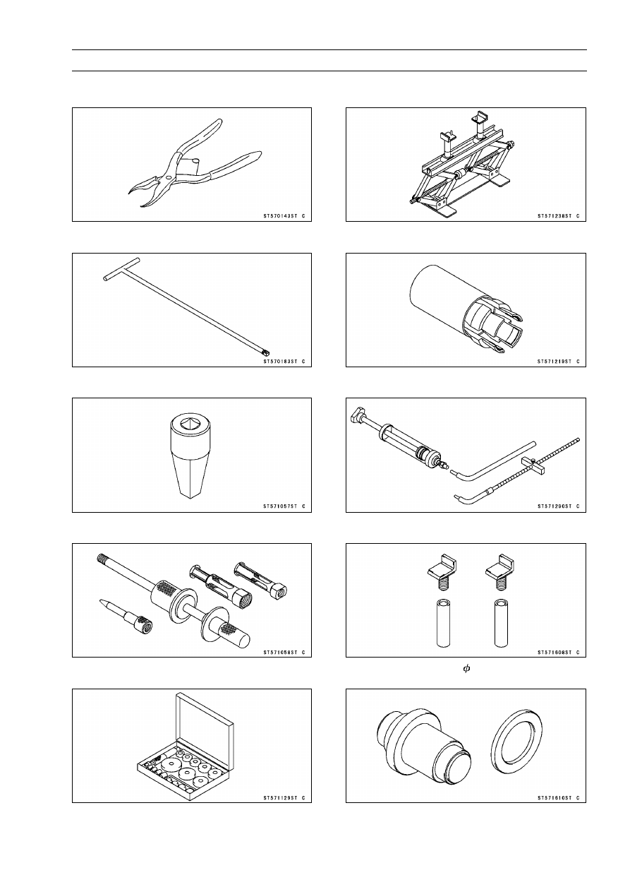
Special Tools

Inside Circlip Pliers:
57001-143

Fork Cylinder Holder Handle:
57001-183

Fork Cylinder Holder Adapter:
57001-1057

Oil Seal & Bearing Remover:
57001-1058

Bearing Driver Set:
57001-1129

Jack:
57001-1238

Front Fork Oil Seal Driver:
57001-1219

Fork Oil Level Gauge:
57001-1290

Jack Attachment:
57001-1608

Needle Bearing Driver,

28:

57001-1610

13-8 SUSPENSION

Special Tools

Spacer,

28:

57001-1663

SUSPENSION 13-9

Front Fork

Front Fork Removal

Remove:

Upper Fairing (see Upper Fairing Removal in the Frame
chapter)
Front Wheel (see Front Wheel Removal in the
Wheels/Tires chapter)
Front Fender (see Front Fender Removal in the Frame
chapter)
Front Wheel Rotation Sensor (ABS equipped models,
see Front Wheel Rotation Sensor Removal in the Brakes
chapter)

Loosen the upper front fork clamp bolt [A] and front fork
top plug [B] beforehand if the fork leg is to be disassem-
bled.

NOTE

Loosen the top plug after loosening the upper front fork
clamp bolt.

Loosen the upper front fork clamp bolt and lower front fork
clamp bolts [C].

With a twisting motion, work the fork leg down and out.

Front Fork Installation

Install the fork with the upper end of the inner tube flush
[A] against the top surface of the stem head [B].

Tighten:

Torque - Front Fork Clamp Bolts (Lower):

21 N·m (2.1

kgf·m, 15 ft·lb)

Front Fork Top Plugs: 25 N·m (2.5 kgf·m, 18 ft·lb)

NOTE

Tighten the top plug before tightening the upper front
fork clamp bolt.

Tighten the two clamp bolts alternately two times to en-
sure even tightening torque.

Tighten:

Torque - Front Fork Clamp Bolts (Upper):

20 N·m (2.0

kgf·m, 15 ft·lb)

Install the removed parts (see appropriate chapters).

Front Fork Oil Change

Remove the front fork (see Front Fork Removal).

Remove:

Top Plug [A] with O-ring
Spacer [B]
Fork Spring Seat [C]
Fork Spring [D]

13-10 SUSPENSION

Front Fork

Compress [A] the fork [B] upside down to draw out the oil
into the suitable container [C].

Hold the fork tube upright, pour in the type and amount of
fork oil specified.

Fork Oil

Viscosity:

KAYABA KHL34-G10 or equivalent

Amount (Per Side):

When changing oil:

EX650C Models

approx. 400 mL (13.5 US oz.)

EX650D Models

approx. 405 mL (13.7 US oz.)

After disassembly and completely dry:

EX650C Models

469 ±4 mL (15.9 ±0.14 US oz.)

EX650D Models

478 ±4 mL (16.2 ±0.14 US oz.)

NOTE

Move the outer tube up and down a few times to remove
the air that is trapped in the fork oil in order to stabilize
the oil level.

Hold the outer tube vertically in a vise and compress the
fork completely.

Wait until the oil level stabilizes.

Use the fork oil level gauge [A] to measure the distance
between the top of the inner tube to the oil level.

Special Tool - Fork Oil Level Gauge: 57001-1290

Set the oil level gauge stopper [B] so that the distance [C]
from the bottom of the stopper to the lower end of the pipe
is the standard oil level distance.

A correct measurement can not be obtained unless the
level gauge pipe is placed in the center of the inner tube.

Oil Level (fully compressed, without spring)

Standard:

EX650C Models

114 ±2 mm (4.49 ±0.08 in.)

EX650D Models

105 ±2 mm (4.13 ±0.08 in.)

Place the stopper of the level gauge at the top [D] of the
inner tube [E] and pull the handle slowly to draw out the
excess oil from fork into the gauge, thus attaining the stan-
dard level.
If not oil is drawn out, there is not enough oil in the fork.
Pour in some more oil and measure again.

SUSPENSION 13-11

Front Fork

Repeat the same procedure for adjusting the other fork.

Install:

Fork Spring [A]
Fork Spring Seat [B]
Spacer [C]

Replace the top plug O-ring with a new one.

Install:

Top Plug
Front Fork (see Front Fork Installation)

Front Fork Disassembly

Remove the front fork (see Front Fork Removal).

Remove:

Top Plug [A] with O-ring
Spacer [B]
Fork Spring Seat [C]
Fork Spring [D]

Drain the fork oil (see Front Fork Oil Change).

Remove the Allen bolt [A] from the bottom of the fork.

Special Tools - Fork Cylinder Holder Handle [B]: 57001-183

Fork Cylinder Holder Adapter [C]: 57001

-1057

NOTE

Hold the outer tube in a vise [D], stop the cylinder unit
[E] from turning by using the special tools, and unscrew
the Allen bolt.

Remove the cylinder unit [A], washer, and the spring [B]
from the inner tube.

Remove the following from the top of the outer tube.

Dust Seal [A]
Retaining Ring [B]

13-12 SUSPENSION

Front Fork

Separate the inner tube [A] from the outer tube [B].

NOTE

From the compressed state, firmly pull down the outer
tube a few times towards the direction of elongation.

Remove the following from the inner tube.

Inner Guide Bushing [A]
Outer Guide Bushing [B]
Washer [C]
Oil Seal [D]

Remove the cylinder base [A] from the bottom of the outer
tube.

Front Fork Assembly

Check the top plug O-ring and replace it with a new one.

Replace the following parts with new ones.

Retaining Ring [A]
Dust Seal [B]
Oil Seal [C]
Inner Guide Bushing [D]
Outer Guide Bushing [E]
Fork Bottom Allen Bolt Gasket [F]

Install the guide bushing on the end of the inner tube.

Insert the cylinder unit and the spring into the inner tube,
and install the cylinder base [A] onto the cylinder end [B]
that protrudes from the bottom.

Install the cylinder base starting with its stepped end.

Be sure that the spring [C] is in position.

Insert the inner tube, cylinder unit, washer, spring, and
cylinder base as a set into the outer tube.

SUSPENSION 13-13

Front Fork

Install the new guide bushing [A] with a use one [B] on it
by tapping the use one with the fork oil seal driver [C].

The split [D] of the bushing should face toward the side of
the motorcycle.

Special Tool - Front Fork Oil Seal Driver: 57001-1219

Install the washer and the oil seal [A] into the outer tube.

Special Tool - Front Fork Oil Seal Driver [B]: 57001-1219

Install the retaining ring on the outer tube.

Apply non-permanent locking agent to the threads of the
bottom Allen bolt [A].

Hold the front fork horizontally in a vise [B].

Hold the cylinder unit [C] with the special tools and tighten
the bottom Allen bolt to secure the cylinder in place.

Special Tools - Fork Cylinder Holder Handle [D]: 57001-183

Fork Cylinder Holder Adapter [E]: 57001

-1057

Torque - Front Fork Bottom Allen Bolt: 30 N·m (3.1 kgf·m,

22 ft·lb)

Pour in the specified type of oil (see Front Fork Oil
Change).

13-14 SUSPENSION

Front Fork

Inner Tube, Outer Tube Inspection

Visually inspect the inner tube [A], and repair any dam-
age.

Nicks or rust damage can sometimes be repaired by using
a wet-stone to remove sharp edges or raised areas which
cause seal damage.
If the damage is not repairable, replace the inner tube.
Since damage to the inner tube damages the oil seal,
replace the oil seal whenever the inner tube is repaired
or replaced.

CAUTION

If the inner tube is badly bent or creased, replace
it.

Excessive bending, followed by subsequent

straightening, can weaken the inner tube.

Temporarily assemble the inner and outer tubes, and
pump them back and forth manually to check for smooth
operation.
If you feel binding or catching, the inner and outer tubes
must be replaced.

WARNING

A straightened inner or outer fork tube may fall in
use, possibly causing an accident. Replace a badly
bent or damaged inner or outer tube and inspect the
other tube carefully before reusing it.

Dust Seal Inspection

Inspect the dust seal [A] for any signs of deterioration or
damage.
Replace it if necessary.

Spring Tension Inspection

Since a spring becomes shorter as it weakens, check its
free length [A] to determine its condition.
If the spring of either fork leg is shorter than the service
limit, it must be replaced. If the length of a replacement
spring and that of the remaining spring vary greatly, the
remaining spring should also be replaced in order to keep
the fork legs balanced for motorcycle stability.

Spring Free Length

Standard:

EX650C Models

294.7 mm (11.60 in.)

EX650D Models

296.2 mm (11.66 in.)

Service Limit:

EX650C Models

289 mm (11.38 in.)

EX650D Models

290 mm (11.42 in.)

SUSPENSION 13-15

Rear Shock Absorber

Spring Preload Adjustment

Using the hook wrench [A], turn the adjusting nut [B] to
adjust the spring preload.

The standard adjuster setting for average-build rider of 68
kg (150 Ib) with no passenger and no accessories is 4th
position.

Spring Preload Setting

Standard Position:

4th position

Adjustable Range:

1st to 7th position

If the compression of the spring is not suited to the op-
erating conditions, adjust it to an appropriate position by
referring to the table below.

Spring Preload Adjustment

Adjuster

Position

Damping

Force

Shock

Absorber

Hardness

Load

Road

Conditions

Driving

Speed

1st

Weak

Soft

Light

Good

Low

7th

Strong

Hard

Heavy

Bad

Highway

Rear Shock Absorber Removal

Remove:

Muffler Body (see Muffler Body Removal in the Engine
Top End chapter)

Raise the rear wheel off the ground using the jack.

Special Tools - Jack: 57001-1238

Jack Attachment: 57001-1608

Squeeze the brake lever slowly and hold it with a band
[A].

WARNING

Be sure to hold the front brake when removing the
shock absorber, or the motorcycle may tall over. It
could cause an accident and injury.

Remove:

Right Stay Cover [A]

13-16 SUSPENSION

Rear Shock Absorber

Remove:

Rear Shock Absorber Bolt (Upper) [A]
Rear Shock Absorber Bolt (Lower) [B], Nut and Washer

Remove the shock absorber [C] backward.

Rear Shock Absorber Installation

Installation is the reverse of removal.

Replace the O-ring of the rear shock absorber bolt (upper)
with a new one.

Apply grease to the lip of oil seals.

Be sure to install the oil seals to the shock absorber.

Fit the O-ring and washer, and then install them.

NOTE

Check that the O-ring is securely installed.

Install the rear shock absorber so that the label side faces
to inside.

Tighten:

Torque - Rear Shock Absorber Bolts: 59 N·m (6.0 kgf·m, 44

ft·lb)

Install the removed parts (see appropriate chapters).

Rear Shock Absorber Inspection

Remove the rear shock absorber (see Rear Shock Ab-
sorber Removal).

Visually inspect the following items.

Smooth Stroke
Oil Leakage
Crack or Dent

If there is any damage to the rear shock absorber, replace
it.

Visually inspect the rubber bushing.
If it show any signs of damage, replace it.

SUSPENSION 13-17

Swingarm

Swingarm Removal

Remove:

Chain Cover Bolts [A]
Quick Rivet [B]
Chain Cover [C]

Free the brake hose [A] from the clamps [B].

For models equipped with an ABS, remove the rear wheel
rotation sensor (see Rear Wheel Rotation Sensor Re-
moval in the Brakes chapter).

Remove:

Muffler Body (see Muffler Body Removal in the Engine
Top End chapter)
Rear Caliper (see Rear Caliper Removal in the Brakes
chapter)

Raise the rear wheel off the ground using the jack.

Special Tools - Jack: 57001-1238

Jack Attachment: 57001-1608

Remove:

Rear

Wheel

(see

Rear

Wheel Removal

in

the

Wheels/Tires chapter)
Drive Chain (see Drive Chain Removal in the Final Drive
chapter)

Remove the lower rear shock absorber nut and bolt [A].

Unscrew the swingarm pivot shaft nut [A].

Pull off the pivot shaft [B], and remove the swingarm.

13-18 SUSPENSION

Swingarm

Swingarm Installation

Installation is the reverse of removal.

Apply grease to the lip of the oil seals.

Be sure to install the oil seal and collar to the swingarm.

Tighten the pivot shaft nut.

Torque - Swingarm Pivot Shaft Nut: 108 N·m (11.0 kgf·m,

80 ft·lb)

Install the removed parts (see appropriate chapters).

Swingarm Bearing Removal

Remove:

Swingarm (see Swingarm Removal)
Collar [A]
Oil Seals [B]
Sleeve [C]
Circlip [D]

Special Tool - Inside Circlip Pliers: 57001-143

Remove the ball bearing and needle bearings.

Special Tool - Oil Seal & Bearing Remover [A]: 57001-1058

Swingarm Bearing Installation

Apply 2 stroke oil to the inner surface of the swingarm.

Replace the ball and needle bearings [A] with new ones.

Install the ball and needle bearings so that the manufac-
turer’s marks face out.

Special Tools - Bearing Driver Set: 57001-1129

Needle Bearing Driver,

28 [B]: 57001-1610

Spacer,

28: 57001-1663

SUSPENSION 13-19

Swingarm

Install the needle bearings [A], ball bearing [B] and oil
seals [C] position as shown.

Circlip [D]
25 mm (0.98 in.) [E]
17 mm (0.67 in.) [F]
1 mm (0.04 in.) [G]
1 mm (0.04 in.) [H]
1 mm (0.04 in.) [I]
23.5 mm (0.93 in.) [J]
5.5 mm (0.22 in.) [K]
Left Side [L]
Right Side [M]

Swingarm Bearing, Sleeve Inspection

CAUTION

Do not remove the bearings for inspection.

Re-

moval may damage them.

Inspect the needle bearings [A] and ball bearing installed
in the swingarm.

The rollers and ball in a bearing normally wear very little,
and wear is difficult to measure. Instead of measuring,
visually inspect the bearing for abrasion, discoloration, or
other damage.
If the needle bearing and sleeve [B] show any sings of
abnormal wear, discoloration, or damage, replace them
as a set.

13-20 SUSPENSION

Swingarm

Turn the bearing in the swingarm back and forth [A] while
checking for plays, roughness, or binding.
If bearing play, roughness, or binding is found, replace
the bearing.

Examine the bearing seal [B] for tears or leakage.
If the seal is torn or is leaking, replace the bearing.

Swingarm Bearing Lubrication

NOTE

Since the bearings are packed with grease and sealed,
lubrication is not required.

Chain Guide Inspection

Refer to the Chain Guide Wear Inspection in the Periodic
Maintenance chapter.

STEERING 14-1

14

Steering

Table of Contents

Exploded View........................................................................................................................

14-2

Special Tools ..........................................................................................................................

14-4

Steering ..................................................................................................................................

14-5

Steering Inspection ...........................................................................................................

14-5

Steering Adjustment..........................................................................................................

14-5

Steering Stem.........................................................................................................................

14-6

Stem, Stem Bearing Removal...........................................................................................

14-6

Stem, Stem Bearing Installation........................................................................................

14-7

Steering Stem Bearing Lubrication ...................................................................................

14-9

Steering Stem Warp Inspection ........................................................................................

14-9

Stem Cap Deterioration, Damage Inspection ...................................................................

14-9

Handlebar ...............................................................................................................................

14-10

Handlebar Removal ..........................................................................................................

14-10

Handlebar Installation .......................................................................................................

14-10

14-2 STEERING

Exploded View

STEERING 14-3

Exploded View

Torque

No.

Fastener

N·m

kgf·m

ft·lb

Remarks

1

Front Fork Clamp Bolts (Lower)

21

2.1

15

AL

2

Front Fork Clamp Bolts (Upper)

20

2.0

15

3

Handlebar Holder Bolts

25

2.5

18

S

4

Handlebar Holder Mounting Nuts

34

3.5

25

5

Switch Housing Screws

3.5

0.36

31 in·lb

6

Steering Stem Head Bolt

108

11.0

80

7

Steering Stem Nut

20

2.0

15

AD: Apply adhesive.

AL: Tighten the two clamp bolts alternately two times to ensure even tighten torque.

G: Apply grease.

L: Apply a non-permanent locking agent.

R: Replacement Parts

S: Follow the specified tightening sequence.

14-4 STEERING

Special Tools

Head Pipe Outer Race Press Shaft:
57001-1075

Steering Stem Nut Wrench:
57001-1100

Bearing Driver Set:
57001-1129

Steering Stem Bearing Driver,

42.5:

57001-1344

Steering Stem Bearing Driver Adapter,

41.5:

57001-1345

Head Pipe Outer Race Driver,

55:

57001-1446

STEERING 14-5

Steering

Steering Inspection

Refer to the Steering Play Inspection in the Periodic Main-
tenance chapter.

Steering Adjustment

Refer to the Steering Play Adjustment in the Periodic
Maintenance chapter.

14-6 STEERING

Steering Stem

Stem, Stem Bearing Removal

Remove:

Upper Fairing (see Upper Fairing Removal in the Frame
chapter)
Front Fender (see Front Fender Removal in the Frame
chapter)
Front Wheel (see Front Wheel Removal in the
Wheels/Tires chapter)
Handlebar (see Handlebar Removal)
Under Bracket (see Under Bracket Removal in the
Frame chapter)
Front Forks (see Front Fork Removal in the Suspension
chapter)
Steering Stem Head (see Steering Play Adjustment in
the Periodic Maintenance chapter)

Bend the claws [A] of claw washer straighten.

Remove the steering stem locknut [B].

Special Tool - Steering Stem Nut Wrench: 57001-1100

Remove the claw washer.

Pushing up the stem base, and remove the steering stem
nut [A] with stem cap [B].

Special Tool - Steering Stem Nut Wrench [C]: 57001-1100

Remove:

Steering Stem [D]
Upper Ball Bearing Inner Race and Ball Bearing

To remove the ball bearing outer races [A] pressed into
the head pipe [B], insert a bar [C] into the recesses of
head pipe, and applying it to both recess alternately ham-
mer it to drive the race out.

NOTE

If either steering stem bearing is damaged, it is recom-
mended that both the upper and lower bearings (includ-
ing outer races) should be replaced with new ones.

STEERING 14-7

Steering Stem

Remove the lower ball bearing inner race (with its oil seal)
[A] which is pressed onto the steering stem with a suitable
commercially available chisel [B].

Stem, Stem Bearing Installation

Replace the bearing outer races with new ones.

Apply grease to the outer races.

Drive them into the head pipe at the same time.

Special Tools - Head Pipe Outer Race Press Shaft [A]:

57001-1075

Bearing Driver Set: 57001-1129
Head Pipe Outer Race Driver,

55 [B]: 57001

-1446

Replace the bearing inner races and oil seal with new
ones.

Apply grease to the oil seal.

Install the oil seal [A] on the steering stem, and drive the
lower ball bearing inner race [B] applied the grease onto
the stem.

Special Tools - Steering Stem Bearing Driver,

42.5 [C]:

57001-1344

Steering Stem Bearing Driver Adapter,

41.5 [D]: 57001-1345

Install the lower ball bearing [A] onto the stem.

Grease the following.

Inner and Outer Races
Lower and Upper Ball Bearings

The lower and upper ball bearings are identical.

14-8 STEERING

Steering Stem

Install the steering stem [A] through the head pipe, and
install the ball bearing [B] and inner race [C] on it.

Apply grease to the stem cap [D].

Install:

Stem Cap
Steering Stem Nut [E]

Settle the bearings in place as follows.

Tighten the steering stem nut with 55 N·m (5.6 kgf·m, 41
ft·lb) 
of torque first, and loosen it a fraction of a turn until
it turns lightly. Afterward tighten it again with specified
torque using a steering stem nut wrench [A].

Check that there is no play and the steering stem turns
smoothly without rattles. If not, the steering stem bearings
may be damaged.

Special Tool - Steering Stem Nut Wrench: 57001-1100

Torque - Steering Stem Nut: 20 N·m (2.0 kgf·m, 15 ft·lb)

Install the claw washer [A] so that its bent side [B] faces
upward, and engage the bent claws with the grooves of
stem locknut [C].

Hand tighten the stem locknut until it touches the claw
washer.

Tighten the stem locknut clockwise until the claws are
aligned with the grooves (ranging from 2nd to 4th) of stem
nut [D], and bend the 2 claws downward [E].

Install the stem head.

Install the washer, and temporary tighten the steering
stem head bolt.

Install the front forks (see Front Fork Installation in the
Suspension chapter).

NOTE

Tighten the upper front fork clamp bolts first, next the
stem head bolt, last the lower front fork clamp bolts.

Tighten the two lower front fork clamp bolts alternately
two times to ensure even tightening torque.

Torque - Front Fork Clamp Bolts (Upper):

20 N·m (2.0

kgf·m, 15 ft·lb)

Steering Stem Head Bolt: 108 N·m (11.0 kgf·m, 80

ft·lb)

Front Fork Clamp Bolts (Lower):

21 N·m (2.1

kgf·m, 15 ft·lb)

WARNING

Do not impede the handlebar turning by routing the
cables, harnesses and hoses improperly (see Ca-
ble, Wire, and Hose Routing section in the Appen-
dix chapter).

Install the removed parts (see appropriate chapters).

STEERING 14-9

Steering Stem

Steering Stem Bearing Lubrication

Refer to the Steering Stem Bearing Lubrication in the Pe-
riodic Maintenance chapter.

Steering Stem Warp Inspection

Whenever the steering stem is removed, or if the steering
can not be adjusted for smooth action, check the steering
stem for straightness.
If the steering stem [A] is bent, replace the steering stem.

Stem Cap Deterioration, Damage Inspection

Replace the stem cap if its oil seal [A] shows damage.

14-10 STEERING

Handlebar

Handlebar Removal

Remove:

Clutch Lever Clamp Bolts [A]
Clutch Lever Assembly [B]
Left Switch Housing [C]
Handlebar Weight [D]
Handlebar Grip [E]

Remove:

Front Master Cylinder [A] (see Front Master Cylinder Re-
moval in the Brakes chapter)
Right Switch Housing [B]
Handlebar Weight [C]
Throttle Grip [D]

Remove:

Handlebar Holder Bolts [A]
Handlebar Holder [B]
Handlebar [C]

Remove:

Cotter Pins [A]
Handlebar Holder Mounting Nuts [B]
Washers
Lower Handlebar Holders [C]

Handlebar Installation

Install the lower handlebar holders [A], noting the letters
“L” [B] and “R” [C].

Install the washers.

Tighten:

Torque - Handlebar Holder Mounting Nuts: 34 N·m (3.5

kgf·m, 25 ft·lb)

Install the cotter pins.

STEERING 14-11

Handlebar

Align the punch mark [A] on the handlebar and the corner
edge [B] on the lower handlebar holder.

Tighten the front holder bolts first, and then the rear holder
bolts. There will be a gap [A] at the rear part of the holder
after tightening.

Torque - Handlebar Holder Bolts: 25 N·m (2.5 kgf·m, 18

ft·lb)

Install:

Throttle Grip
Throttle Cable Tips [A]
Right Switch Housing

Fit the projection [B] into a hole [C] in the handlebar.

Tighten:

Torque - Switch Housing Screws: 3.5 N·m (0.36 kgf·m, 31

in·lb)

Apply a non-permanent locking agent to the right handle-
bar weight bolt.

Install the front brake master cylinder (see Front Master
Cylinder Installation in the Brakes chapter).

Apply adhesive cement to the inside of the left handlebar
grip.

Apply a non-permanent locking agent to the left handlebar
weight bolt.

Install the left switch housing.

Fit the projection [A] into a hole [B] in the handlebar.

Tighten:

Torque - Switch Housing Screws: 3.5 N·m (0.36 kgf·m, 31

in·lb)

Install the clutch lever (see Clutch Lever Installation in the
Clutch chapter).

FRAME 15-1

15

Frame

Table of Contents

Exploded View...................................

15-2

Seat ...................................................

15-8

Seat Removal ..............................

15-8

Seat Installation ...........................

15-8

Fairings..............................................

15-9

Lower Fairing Removal ................

15-9

Lower Fairing Installation .............

15-9

Lower Fairing Bracket Removal...

15-9

Lower Fairing Bracket Installation

15-10

Upper Fairing Cover Removal .....

15-10

Upper Fairing Cover Installation ..

15-10

Upper Fairing Removal ................

15-10

Upper Fairing Installation .............

15-11

Upper Fairing Disassembly..........

15-11

Upper Fairing Assembly...............

15-12

Upper Inner Fairing Removal.......

15-13

Upper Inner Fairing Installation....

15-13

Upper Fairing Bracket Removal...

15-13

Upper Fairing Bracket Installation

15-14

Under Bracket Removal...............

15-14

Under Bracket Installation............

15-14

Inner Fairing Removal..................

15-14

Inner Fairing Installation...............

15-15

Side Covers .......................................

15-16

Side Cover Removal ....................

15-16

Side Cover Installation .................

15-16

Seat Covers.......................................

15-17

Seat Cover Removal....................

15-17

Seat Cover Installation.................

15-17

Fenders .............................................

15-19

Front Fender Removal .................

15-19

Front Fender Installation ..............

15-19

Flap Removal...............................

15-19

Flap Installation............................

15-19

Rear Fender Removal..................

15-20

Rear Fender Installation...............

15-20

Frame ................................................

15-21

Frame Inspection .........................

15-21

Battery Case......................................

15-22

Battery Case Removal .................

15-22

Battery Case Installation ..............

15-23

Footpeg Stay .....................................

15-24

Footpeg Stay Removal ................

15-24

Footpeg Stay Installation .............

15-24

Windshield .........................................

15-25

Windshield Removal ....................

15-25

Windshield Installation .................

15-25

Sidestand...........................................

15-26

Sidestand Removal......................

15-26

Sidestand Installation...................

15-26

Frame Cover......................................

15-27

Frame Cover Removal.................

15-27

Frame Cover Installation..............

15-27

Rear View Mirrors ..............................

15-28

Rear View Mirror Removal ..........

15-28

Rear View Mirror Installation........

15-28

15-2 FRAME

Exploded View

FRAME 15-3

Exploded View

Torque

No.

Fastener

N·m

kgf·m

ft·lb

Remarks

1

Footpeg Stay Bolts

25

2.5

18

S

2

Sidestand Bolt

44

4.5

32

3

Sidestand Switch Bolt

8.8

0.90

78 in·lb

L

4. US, CA, CAL and SEA Models
5. AU Model

G: Apply grease.

L: Apply a non-permanent locking agent.

R: Replacement Parts

S: Follow the specified tightening sequence.

15-4 FRAME

Exploded View

FRAME 15-5

Exploded View

Torque

No.

Fastener

N·m

kgf·m

ft·lb

Remarks

1

Lower Fairing Mounting Bolts

8.8

0.90

78 in·lb

2

Lower Fairing Bracket Bolts

12

1.2

106 in·lb

L

3

Front Turn Signal Light Mounting Screws

1.2

0.12

11 in·lb

L: Apply a non-permanent locking agent.

15-6 FRAME

Exploded View


Content      ..     12      13      14      15     ..