Kawasaki Ninja 650R, ER-6f, ER-6f ABS Motorcycle. Service Manual (2009-2011 year) - page 13
 

  Index      Manuals     Kawasaki Ninja 650R, ER-6f, ER-6f ABS Motorcycle. Service Manual (2009-2011 year)


Search            copyright infringement  


Content      ..     11      12      13      14     ..


Kawasaki Ninja 650R, ER-6f, ER-6f ABS Motorcycle. Service Manual (2009-2011 year) - page 13


BRAKES 12-35

Anti-Lock Brake System (Equipped Models)

ABS Troubleshooting Outline

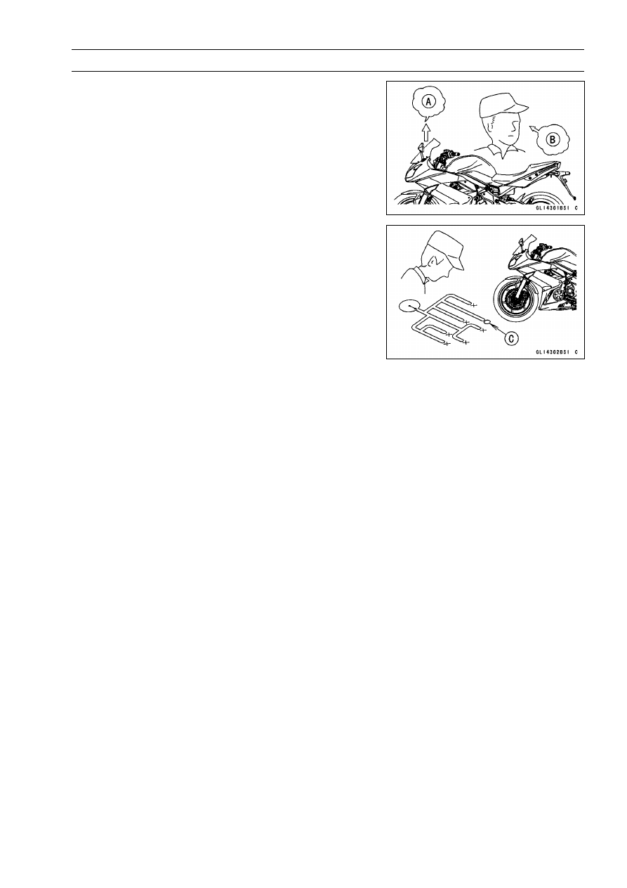
When an abnormality in the system occurs, the ABS in-

dicator light (LED) lights up to alert the rider. In addition,
the nature of the fault is stored in the memory of the ABS
hydraulic unit and when in the self-diagnosis mode, the ser-
vice code [A] is indicated by the number of times the ABS
indicator light (LED) blinks. The service codes stored in
memory are not erased until the mode has been changed
to the fault erase mode after the fault has been corrected.
Therefore, after correcting the problem, always erase the
service codes and then run the self-diagnosis program to
confirm normal signal output. When, due to a malfunction,
the ABS indicator light (LED) remains lit, get a thorough
understanding of the background before starting the repair
work. Ask the rider about the conditions [B] under which
the problem occurred and try to determine the cause [C].
Do not rely solely on the ABS self-diagnosis function, use
common sense; check the brakes for proper braking power,
and brake fluid level, search for leaks, etc.

Even when the ABS is operating normally, the ABS indi-

cator light (LED) may light up under the conditions listed be-
low. Turn the ignition switch OFF to stop the indicator light.
If the motorcycle runs without erasing the service code, the
light may light up again.

After continuous riding on a rough road.

When the engine is started with the stand raised and the
transmission engaged, and the rear wheel turns.

When accelerating so abruptly that the front wheel leaves
the ground.

When the ABS has been subjected to strong electrical
interference.

When tire pressure is abnormal. Adjust tire pressure.

When a tire different in size from the standard size is being
used. Replace with standard size.

When the wheel is deformed. Replace the wheel.

Much of the ABS troubleshooting work consists of con-

firming continuity of the wiring. The ABS parts are assem-
bled and adjusted by the manufacturer, so there is no need
to disassemble or repair them. Replace the ABS hydraulic
unit.

The basic troubleshooting procedures are listed below.

Carry out pre-diagnosis inspections as a preliminary in-
spection.

Determine the fault using the self-diagnosis function.

Check wiring and connections from the ABS hydraulic
unit connector to the suspected faulty ABS part, using the
hand tester.

Special Tool - Hand Tester: 57001-1394

12-36 BRAKES

Anti-Lock Brake System (Equipped Models)

Visually inspect the wiring for signs of burning or fraying.
If any wiring is poor, replace the damaged wiring.

Pull each connector [A] apart and inspect it for corrosion,
dirt and damage.
If the connector is corroded or dirty, clean it carefully. If it
is damaged, replace it.

Check the wiring for continuity.

Use the wiring diagram to find the ends of the lead which
is suspected of being a problem.

Connect the hand tester between the ends of the leads.

Special Tool - Hand Tester: 57001-1394

Set the tester to the × 1

range, and read the tester.

If the tester does not read 0

, the lead is defective. Re-

place the main harness [B] if necessary.

Narrow down suspicious parts and close in on the faulty
ABS part by repeating the continuity tests.
If no abnormality is found in the wiring or connectors, the
ABS parts are the next likely suspects. Check each part
one by one.
If an abnormality is found, replace the affected ABS part.

BRAKES 12-37

Anti-Lock Brake System (Equipped Models)

ABS Diagnosis Flow Chart

12-38 BRAKES

Anti-Lock Brake System (Equipped Models)

Inquiries to Rider

Each rider reacts to problems in different ways, so it is important to confirm what kind of condition
the rider is dissatisfied with.

Try to find out exactly what problem occurs under exactly what conditions by asking the rider; know-
ing this information may help you reproduce the problem in the shop.

The diagnosis sheet will help prevent you from overlooking any keys, so always use it.

Sample Diagnosis Sheet

Rider name:

Registration No. (license plate No.):

Year of initial registration:

Model:

Engine No.:

Frame No.:

Date problem occurred:

Frequency:

Weather:

Mileage:

Brake
lever
vibration
or noise

Indicator
light
blinks

Abnor-
mal
brake
lever
move-
ment

Phenome-
non

Pedal
vibration
or noise

Indicator
light
remains
lit up

Braking
distance
too long

Abnor-
mal
pedal
move-
ment

ABS not
working

ABS
works
but
indicator
light
doesn’t
light up

ABS op-
erating
too fre-
quently

Engine conditions at
problem

At start-up

After starting

At 5 000 r/min (rpm)
or more

Road conditions

Slippery road

(

snow,

gravel,

other

)

Rough surface

Other

Driving conditions

High-speed cornering

Driving 10 km/h (6 mph) or above

Driving below 10 km/h (6 mph)

When stopping

When turning

Brake application

Gradual

Abrupt

Other conditions

Large brake lever stroke

Large pedal stroke

BRAKES 12-39

Anti-Lock Brake System (Equipped Models)

Pre-Diagnosis Inspection 1

12-40 BRAKES

Anti-Lock Brake System (Equipped Models)

Pre-Diagnosis Inspection 2

Self-diagnosis Outline

When the indicator light has blinked or come on, the ABS hydraulic unit memorizes and stores the

service code (15 codes including “Normal Code”) for the service person to troubleshoot easily. The
service code memory is powered directly by the battery and cannot be canceled by the ignition switch.

The ABS hydraulic unit can memorize up to six service codes. Further service codes are memorized

after erasing the preceding six service codes. If there is no fault, only the start code 12 is shown,
indicating that “The ABS is normal”.

Self-diagnosis Procedures

When a problem occurs with the ABS system, the ABS
indicator light (LED) [A] lights.

NOTE

Use

a

fully

charged

battery

when

conducting

self-diagnosis. Otherwise, the light blinks very slowly
or does not blink.

The motorcycle is stopped.

Keep the self-diagnosis terminal grounded during self
-diagnosis, with an auxiliary lead.

BRAKES 12-41

Anti-Lock Brake System (Equipped Models)

Remove the seat (see Seat Removal in the Frame chap-
ter).

Ground the self-diagnosis terminal [A] (Gray) to the bat-
tery (–) terminal or battery (–) cable connector, using a
lead [B].

Turn on the ignition switch.

Count the blinks of the light to read the service code.
Keep the auxiliary lead ground until you finish reading the
service code.

Service Code Clearing Procedures

Start the service code erase mode with the following pro-
cedure.

The erase mode starts when the ABS self-diagnosis ter-
minal is disconnected from the ground terminal after start-
ing the self-diagnosis mode.

The service code can be erased by grounding and un-
grounding (each time for at least one second) the ABS
self-diagnosis terminal three times or more within about
12.5 seconds after starting the erase mode.

The ABS indicator light (LED) remains lit during the erase
mode and after erasing.

Once erasing is finished, enter the self-diagnosis mode
again to confirm that the service codes have been
erased. If the ABS has been reset and all codes have
been erased, only start code 12 will be shown.

12-42 BRAKES

Anti-Lock Brake System (Equipped Models)

Self-diagnosis Flow Chart

BRAKES 12-43

Anti-Lock Brake System (Equipped Models)

How to Read Service Codes

Service codes are shown by a series of long and short blinks of the ABS indicator light (LED) as
shown below.

Read 10th digit and unit digit as the ABS indicator light (LED) blinks.

When there are a number of faults, a maximum of six service codes can be stored and the display
will begin starting from the last service code entered.

For the display pattern, first, start code 12 is shown, next up to six service codes starting with the
last one stored, then the display is repeated from the start code once again.

If there is no fault, only the start code is shown.

How to Erase Service Codes

Even if the ignition switch is turned OFF, the battery or the ABS hydraulic unit are disconnected, all
service codes remain in the ABS hydraulic unit.

Refer to the Service Code Clearing Procedure for the service code erasure.

12-44 BRAKES

Anti-Lock Brake System (Equipped Models)

Service Code Table

Service

Code

ABS Indicator Light (LED)

Problems

Light State

12

Start code (not fault)

After starts,

turn off

13

Rear inlet solenoid valve trouble (open,
temperature abnormal)

ON

14

Rear outlet solenoid valve trouble (open,
temperature abnormal)

ON

17

Front inlet solenoid valve trouble (open,
temperature abnormal)

ON

18

Front outlet solenoid valve trouble (open,
temperature abnormal)

ON

19

ABS solenoid valve relay trouble (wiring
shorted or open, stuck relay (ON or OFF)
or dropout)

ON

25

Front, rear wheel rotation difference
abnormal (substandard tire, sensor rotor
teeth number wrong)

ON

35

ABS motor relay trouble (wiring shorted or
open, stuck relay (ON or OFF)

ON

42

Front wheel rotation sensor signal abnormal
(sensor or rotor missing, too large
clearance, rotor tooth worn or missing)

ON

43

Front wheel rotation sensor wiring (wiring
shorted or open, connector bad connection)

ON

44

Rear wheel rotation sensor signal abnormal
(sensor or rotor missing, too large
clearance, rotor tooth worn or missing)

ON

45

Rear wheel rotation sensor wiring (wiring
shorted or open, connector bad connection)

ON

52

Power supply voltage abnormal
(under-voltage)

ON

53

Power supply voltage abnormal
(over-voltage)

ON

55

ECU trouble (ECU operation abnormal)

ON

BRAKES 12-45

Anti-Lock Brake System (Equipped Models)

ABS Indicator Light (LED) Inspection

Turn the ignition switch ON.
If the ABS indicator light (LED) [A] lights, it is normal.
If the ABS indicator light (LED) does not light, check
the meter unit (see Electronic Combination Meter Unit
Inspection in the Electrical System chapter).
If the meter unit is normal, proceed to the 2nd step.

Do the 2nd step test.

Check for continuity between the orange/black lead ter-
minal of the main harness side connector [A] and ground.

Special Tool - Hand Tester: 57001-1394

If there is the continuity in the lead, replace or repair the
main harness.
If there is not the continuity in the lead, proceed to the 3rd
step.

Do the 3rd step test.

Disconnect the ABS hydraulic unit connector and meter
connector.

Check for continuity between the orange/black lead
terminal of the main harness side connector [A] and
orange/black lead terminal of the main harness side
connector [B].
If there is the continuity in the lead, replace the ABS hy-
draulic unit.
If there is not the continuity in the lead, replace or repair
the main harness.

Solenoid Valve Inspection (Service Code
13,14,17,18)

Do the 1st step test.

Recheck the service code indication; erase the service
code, perform the pre-diagnosis inspection 1 and 2, and
retrieve the service code.
If the ABS indicator light (LED) [A] lit, faulty solenoid valve
in the ABS hydraulic unit. Replace the ABS hydraulic unit.
If the ABS indicator light (LED) unlit, ABS system is nor-
mal (service code is not stored; temporary failure.).

ABS Solenoid Valve Relay Inspection (Service
Code 19)

Do the 1st step test.

Check the ABS solenoid valve relay fuse [A].
If the fuse blown, 2nd step.
If the fuse correct, 4th step.

12-46 BRAKES

Anti-Lock Brake System (Equipped Models)

Do the 2nd step test.

Disconnect the ABS hydraulic unit connector [A].

Check for continuity between the white/red and black/yel-
low lead terminals of the ABS hydraulic unit connector.
If there is the continuity in the lead, replace the ABS hy-
draulic unit.
If there is not the continuity in the lead, 3rd step.

Do the 3rd step test.

Check for continuity between the white/red lead terminal
of the main harness side connector [A] and white/red lead
terminal of the fuse box [B].
If there is the continuity in the lead, replace the fuse.
If there is not the continuity in the lead, replace or repair
the main harness.

Do the 4th step test.

Check the battery terminal voltage between the white/red
lead terminal of the fuse box [A] and ground.

Special Tool - Hand Tester: 57001-1394

Battery Terminal Voltage

Standard:

Battery Voltage

If the battery terminal voltage is not within the specifica-
tion, 5th step.
If the battery terminal voltage correct, 6th step.

Do the 5th step test.

Check for continuity between the positive (+) cable [A] of
the battery and white/red lead terminal of the main har-
ness side connector [B].
If there is the continuity in the lead, 4th step.
If there is not the continuity in the lead, replace or repair
the main harness.

Do the 6th step test.

Recheck the service code indication; erase the service
code, perform the pre-diagnosis inspection 1 and 2, and
retrieve the service code.
If the ABS indicator light (LED) [A] lit, faulty ABS solenoid
valve relay in the ABS hydraulic unit. Replace the ABS
hydraulic unit.
If the ABS indicator light (LED) unlit, ABS system is nor-
mal (service code is not stored; temporary failure.).

BRAKES 12-47

Anti-Lock Brake System (Equipped Models)

Front, Rear Wheel Rotation Difference Abnormal
(Service Code 25)

Do the 1st step test.

Check the following and correct the faulty part.

Incorrect the tire pressure.
Tires not recommended for the motorcycle were installed
(incorrect tire size).
Deformation of the wheel or tire.
Sensor rotor for missing teeth and clogging with foreign
matter.

If the all parts correct, 2nd step.

Do the 2nd step test.

Recheck the service code indication; erase the service
code, perform the pre-diagnosis inspection 1 and 2, and
retrieve the service code.
If the ABS indicator light (LED) [A] lit, faulty ECU in the
ABS hydraulic unit. Replace the ABS hydraulic unit.
If the ABS indicator light (LED) unlit, ABS system is nor-
mal (service code is not stored; temporary failure.).

ABS Motor Relay Inspection (Service Code 35)

Do the 1st step test.

Check the ABS motor relay fuse [A].
If the fuse blown, 2nd step.
If the fuse correct, 4th step.

Do the 2nd step test.

Disconnect the ABS hydraulic unit connector.

Check for continuity between the red/white and black/yel-
low lead terminals of the ABS hydraulic unit connector [A].
If there is the continuity in the lead, replace the ABS hy-
draulic unit.
If there is not the continuity in the lead, 3rd step.

Do the 3rd step test.

Check for continuity between the red/white lead terminal
of the main harness side connector [A] and red/white lead
terminal of the fuse box [B].
If there is the continuity in the lead, replace the fuse.
If there is not the continuity in the lead, replace or repair
the main harness.

12-48 BRAKES

Anti-Lock Brake System (Equipped Models)

Do the 4th step test.

Check the battery terminal voltage between the red/white
lead terminal of the fuse box [A] and ground.

Special Tool - Hand Tester: 57001-1394

Battery Terminal Voltage

Standard:

Battery Voltage

If the battery terminal voltage is not within the specifica-
tion, 5th step.
If the battery terminal voltage correct, 6th step.

Do the 5th step test.

Check for continuity between the positive (+) cable [A] of
the battery and red/white lead terminal of the main har-
ness side connector [B].
If there is the continuity in the lead, 4th step.
If there is not the continuity in the lead, replace or repair
the main harness.

Do the 6th step test.

Recheck the service code indication; erase the service
code, perform the pre-diagnosis inspection 1 and 2, and
retrieve the service code.
If the ABS indicator light (LED) [A] lit, faulty ABS motor re-
lay in the ABS hydraulic unit. Replace the ABS hydraulic
unit.
If the ABS indicator light (LED) unlit, ABS system is nor-
mal (service code is not stored; temporary failure.).

Front Wheel Rotation Sensor Signal Abnormal
(Service Code 42)

Do the 1st step test.

Measure the air gap between the front wheel rotation sen-
sor and sensor rotor.

Thickness Gauge [A]

Air Gap

Standard:

1 mm (0.04 in.)

If the measurement is over standard, check each part
for deformation and looseness and correct accordingly.
Recheck the air gap.
If the measurement is correct, 2nd step.

BRAKES 12-49

Anti-Lock Brake System (Equipped Models)

Do the 2nd step test.

Check that there is iron or other magnetic deposits be-
tween the sensor [A] and sensor rotor [B], and the sensor
rotor slots for obstructions.

Check the installation condition of the sensor for loose-
ness.

Check the sensor and sensor rotor tip for deformation or
damage (e.g., chipped sensor rotor teeth).
If the sensor and sensor rotor in bad condition, remove the
any deposits. Install the properly or replace faulty part.
If the all correct, 3rd step.

Do the 3rd step test.

Recheck the service code indication; erase the service
code, perform the pre-diagnosis inspection 1 and 2, and
retrieve the service code.
If the ABS indicator light (LED) [A] lit, faulty ECU in the
ABS hydraulic unit. Replace the ABS hydraulic unit.
If the ABS indicator light (LED) unlit, ABS system is nor-
mal (service code is not stored; temporary failure.).

Front Wheel Rotation Sensor Wiring Inspection
(Service Code 43)

Do the 1st step test.

Disconnect the ABS hydraulic unit connector and front
wheel rotation sensor connector.

Short the white and black lead terminals of the main har-
ness side connector [A] with a jumper lead, and check for
continuity between the white and black lead terminals of
the main harness side connector [B].
If there is the continuity in the lead, 2nd step.
If there is not the continuity in the lead, replace or repair
the main harness.

Do the 2nd step test.

Check for continuity between the white lead terminal of
the sensor connector [A] and ground, and black lead ter-
minal of the sensor connector and ground.
If there is the continuity in the lead, replace the front wheel
rotation sensor.
If there is not the continuity in the lead, 3rd step.

12-50 BRAKES

Anti-Lock Brake System (Equipped Models)

Do the 3rd step test.

Recheck the service code indication; erase the service
code, perform the pre-diagnosis inspection 1 and 2, and
retrieve the service code.
If the ABS indicator light (LED) [A] lit, faulty ECU in the
ABS hydraulic unit. Replace the ABS hydraulic unit.
If the ABS indicator light (LED) unlit, ABS system is nor-
mal (service code is not stored; temporary failure.).

Rear Wheel Rotation Sensor Signal Abnormal
(Service Code 44)

Do the 1st step test.

Measure the air gap between the rear wheel rotation sen-
sor and sensor rotor.

Thickness Gauge [A]

Air Gap

Standard:

1 mm (0.04 in.)

If the measurement is over standard, check each part
for deformation and looseness and correct accordingly.
Recheck the air gap.
If the measurement is correct, 2nd step.

Do the 2nd step test.

Check that there is iron or other magnetic deposits be-
tween the sensor [A] and sensor rotor [B], and the sensor
rotor slots for obstructions.

Check the installation condition of the sensor for loose-
ness.

Check the sensor and sensor rotor tip for deformation or
damage (e.g., chipped sensor rotor teeth).
If the sensor and sensor rotor in bad condition, remove the
any deposits. Install the properly or replace faulty part.
If the all correct, 3rd step.

Do the 3rd step test.

Recheck the service code indication; erase the service
code, perform the pre-diagnosis inspection 1 and 2, and
retrieve the service code.
If the ABS indicator light (LED) [A] lit, faulty ECU in the
ABS hydraulic unit. Replace the ABS hydraulic unit.
If the ABS indicator light (LED) unlit, ABS system is nor-
mal (service code is not stored; temporary failure.).

BRAKES 12-51

Anti-Lock Brake System (Equipped Models)

Rear Wheel Rotation Sensor Wiring Inspection
(Service Code 45)

Do the 1st step test.

Disconnect the ABS hydraulic unit connector and rear
wheel rotation sensor connector.

Short the red and green lead terminals of the main har-
ness side connector [A] with a jumper lead, and check for
continuity between the red and green lead terminals of
the main harness side connector [B].
If there is the continuity in the lead, 2nd step.
If there is not the continuity in the lead, replace or repair
the main harness.

Do the 2nd step test.

Check for continuity between the white lead terminal of
the sensor connector [A] and ground, and black lead ter-
minal of the sensor connector and ground.
If there is the continuity in the lead, replace the rear wheel
rotation sensor.
If there is not the continuity in the lead, 3rd step.

Do the 3rd step test.

Recheck the service code indication; erase the service
code, perform the pre-diagnosis inspection 1 and 2, and
retrieve the service code.
If the ABS indicator light (LED) [A] lit, faulty ECU in the
ABS hydraulic unit. Replace the ABS hydraulic unit.
If the ABS indicator light (LED) unlit, ABS system is nor-
mal (service code is not stored; temporary failure.).

Power Supply Voltage Abnormal (Under-Voltage)
(Service Code 52)

Do the 1st step test.

Disconnect the ABS Kawasaki diagnostic system connec-
tor and ABS hydraulic unit connector.

Check for continuity between the brown lead terminal of
the main harness side connector [A] and brown lead ter-
minal of the main harness side [B].
If there is the continuity in the lead, 2nd step.
If there is not the continuity in the lead, replace or repair
the main harness.

12-52 BRAKES

Anti-Lock Brake System (Equipped Models)

Do the 2nd step test.

Connect the ABS Kawasaki diagnostic system connector
and ABS hydraulic unit connector.

Check the battery terminal voltage, connect the hand
tester to the brown terminal of ABS Kawasaki diagnostic
system connector [A] and ground.

Special Tool - Hand Tester: 57001-1394

Turn the ignition switch ON.

Battery Terminal Voltage

Standard:

9.6 V or more

If the battery terminal voltage is not within the specifica-
tion, 3rd step.
If the battery terminal voltage correct, 4th step.

Do the 3rd step test.

Inspect the following parts.

Battery (see Charging Condition Inspection in the Elec-
trical System chapter)
Ignition Switch (see Switch Inspection in the Electrical
System chapter)
Main Harness (see Wiring Inspection in the Electrical
System chapter)
Main Fuse 30 A (see Fuse Inspection in the Electrical
System chapter)

Do the 4th step test.

Recheck the service code indication; erase the service
code, perform the pre-diagnosis inspection 1 and 2, and
retrieve the service code.
If the ABS indicator light (LED) [A] lit, faulty ECU in the
ABS hydraulic unit. Replace the ABS hydraulic unit.
If the ABS indicator light (LED) unlit, ABS system is nor-
mal (service code is not stored; temporary failure.).

Power Supply Voltage Abnormal (Over-Voltage)
(Service Code 53)

Do the 1st step test.

Disconnect the ABS Kawasaki diagnostic system connec-
tor and ABS hydraulic unit connector.

Check for continuity between the brown lead terminal of
the main harness side connector [A] and brown lead ter-
minal of the main harness side [B].
If there is the continuity in the lead, 2nd step.
If there is not the continuity in the lead, replace or repair
the main harness.

BRAKES 12-53

Anti-Lock Brake System (Equipped Models)

Do the 2nd step test.

Connect the ABS Kawasaki diagnostic system connector
and ABS hydraulic unit connector.

Check the battery terminal voltage, connect the hand
tester to the brown terminal of ABS Kawasaki diagnostic
system connector [A] and ground.

Special Tool - Hand Tester: 57001-1394

Turn the ignition switch ON.

Battery Terminal Voltage

Standard:

16.6 V or less

If the battery terminal voltage is not within the specifica-
tion, 3rd step.
If the battery terminal voltage correct, 4th step.

Do the 3rd step test.

Check the battery condition and regulator/rectifier (see
Charging Condition Inspection, Regulator/Rectifier In-
spection in the Electrical System chapter).

Do the 4th step test.

Recheck the service code indication; erase the service
code, perform the pre-diagnosis inspection 1 and 2, and
retrieve the service code.
If the ABS indicator light (LED) [A] lit, faulty ECU in the
ABS hydraulic unit. Replace the ABS hydraulic unit.
If the ABS indicator light (LED) unlit, ABS system is nor-
mal (service code is not stored; temporary failure.).

ECU Inspection (Service Code 55)

Do the 1st step test.

Recheck the service code indication; erase the service
code, perform the pre-diagnosis inspection 1 and 2, and
retrieve the service code.
If the ABS indicator light (LED) [A] lit, faulty ECU in the
ABS hydraulic unit. Replace the ABS hydraulic unit.
If the ABS indicator light (LED) unlit, ABS system is nor-
mal (service code is not stored; temporary failure.).

12-54 BRAKES

Anti-Lock Brake System (Equipped Models)

ABS Hydraulic Unit Removal

CAUTION

The ABS hydraulic unit [A] has been adjusted
and set with precision at the factory. Therefore, it
should be handled carefully, never struck sharply,
as with a hammer, or allowed to fall on a hard
surface.
Be careful not to get water or mud on the ABS hy-
draulic unit.

Drain the brake fluid from the front and rear brake lines.

Drain the brake fluid through the bleed valve by pumping
the brake lever and pedal.

Remove:

Battery Case (see Battery Case Removal in the Frame
chapter)
Muffler Body (see Muffler Body Removal in the Engine
Top End chapter)
Regulator/Rectifier (see Regulator/Rectifier Removal in
the Electrical System chapter)

Raise the rear wheel off the ground using the jack.

Special Tools - Jack: 57001-1238

Jack Attachment: 57001-1608

Put a block in front of the front wheel to stop moving.

Remove the rear shock absorber bolt and nut (lower), and
lower the swingarm.

Clean the ABS hydraulic unit.

CAUTION

Clean all fittings on the ABS hydraulic unit and the
rear master cylinder because dirt around the banjo
bolts could contaminate the brake fluid in the line
during removal/installation.
Spread out a shop towel around the ABS hydraulic
unit before removing the brake line so that brake
fluid does not leak on the parts.

Remove the bolts [A].

BRAKES 12-55

Anti-Lock Brake System (Equipped Models)

Remove the brake pipe joint nuts [A].

Tape the brake line opening to prevent brake fluid leakage
or contamination by foreign matter.

CAUTION

Brake fluid quickly ruins painted plastic surfaces;
any spilled fluid should be completely washed away
immediately.

Disconnect the connector [A].

Pull the lever [B] as shown.

Remove the ABS hydraulic unit with its bracket.

Remove:

Nuts [A] and Bracket [B]

CAUTION

The ABS hydraulic unit has been adjusted and set
with precision at the factory. Do not try to disas-
semble and repair the ABS hydraulic unit.

ABS Hydraulic Unit Installation

Install the bracket to the ABS hydraulic unit.

CAUTION

Brake fluid quickly ruins painted plastic surfaces;
any spilled fluid should be completely washed away
immediately.

Route the lead correctly, and join the connector securely.

Route the brake pipes correctly (see Cable, Wire, and
Hose Routing section in the Appendix chapter).

Install the brake pipes.

To Rear Master Cylinder [A]
To Rear Caliper [B]
To Front Master Cylinder [C]
To Front Calipers [D]

Tighten:

Torque - Brake Pipe Joint Nuts: 18 N·m (1.8 kgf·m, 13 ft·lb)

Install the ABS hydraulic unit to the frame.

12-56 BRAKES

Anti-Lock Brake System (Equipped Models)

ABS Hydraulic Unit Inspection

Remove the ABS hydraulic unit (see ABS Hydraulic Unit
Removal).

Visually inspect the ABS hydraulic unit.
Replace the ABS hydraulic unit if any of them are cracked,
or otherwise damaged.

Visually inspect the connector terminals [A].
Replace the ABS hydraulic unit or main harness if either
of the terminals are cracked, bent, or otherwise damaged.
If the ABS hydraulic unit connector is clogged with mud
or dust, blow it off with compressed air.

Front Wheel Rotation Sensor Removal

CAUTION

The wheel rotation sensor should be handled care-
fully, never struck sharply, as with a hammer, or al-
lowed to fall on a hard surface since the wheel rota-
tion sensor is precision made. Be careful not to get
water or mud on the wheel rotation sensor.
Do not try to disassemble or repair the wheel rota-
tion sensor.

Remove:

Fuel Tank (see Fuel Tank Removal in the Fuel System
(DFI) chapter)
Nut [A] and Clamp

Free the sensor lead from the clamp [A].

BRAKES 12-57

Anti-Lock Brake System (Equipped Models)

Disconnect the connector [A].

Remove:

Bolt [A]
Front Wheel Rotation Sensor [B]

Free the sensor lead from the clamps.

Front Wheel Rotation Sensor Installation

Installation is the reverse of removal.

Route the lead correctly (see Cable, Wire, and Hose
Routing section in the Appendix chapter).

Torque - Front Wheel Rotation Sensor: 20 N·m (2.0 kgf·m,

15 ft·lb)

Rear Wheel Rotation Sensor Removal

CAUTION

The wheel rotation sensor should be handled care-
fully, never struck sharply, as with a hammer, or al-
lowed to fall on a hard surface since the wheel rota-
tion sensor is precision made. Be careful not to get
water or mud on the wheel rotation sensor.
Do not try to disassemble or repair the wheel rota-
tion sensor.

Remove:

Right Frame Cover (see Frame Cover Removal in the
Frame chapter)

Disconnect the connector [A].

12-58 BRAKES

Anti-Lock Brake System (Equipped Models)

Remove:

Bolt [A]
Rear Wheel Rotation Sensor [B]

Free the sensor lead from the clamps.

Rear Wheel Rotation Sensor Installation

Installation is the reverse of removal.

Route the lead correctly (see Cable, Wire, and Hose
Routing section in the Appendix chapter).

Torque - Rear Wheel Rotation Sensor: 20 N·m (2.0 kgf·m,

15 ft·lb)

Wheel Rotation Sensor Inspection

Remove the front wheel rotation sensor [A] from the front
fork.

Remove the rear wheel rotation sensor [B] from the
caliper bracket.

Visually inspect the wheel rotation sensors.
Replace the wheel rotation sensor if it is cracked, bent, or
otherwise damaged.

Wheel Rotation Sensor Air Gap Inspection

Raise the front/rear wheel off the ground (see Front/Rear
Wheel Removal in the Wheels/Tires chapter).

Measure the air gap between the sensor and sensor rotor
at several points by turning the wheel slowly.

Thickness Gauge [A]

Air Gap

Standard:

Front

1 mm (0.04 in.)

Rear

1 mm (0.04 in.)

NOTE

The sensor air gap cannot be adjusted.

If the air gap is not within the specification, inspect the hub
bearing (see Hub Bearing Inspection in the Wheels/Tires
chapter), sensor installation condition and sensor (see
Wheel Rotation Sensor Inspection).

BRAKES 12-59

Anti-Lock Brake System (Equipped Models)

Wheel Rotation Sensor Rotor Inspection

Remove the front/rear brake discs (see Brake Disc Re-
moval).

Visually inspect the wheel rotation sensor rotor.
If the rotor is deformed or damaged (chipped teeth [A]),
replace the sensor rotor with the brake disc.
If there is iron or other magnetic deposits [B], remove the
deposits.

Brake Hose and Pipe Removal/Installation

Refer to the Brake Hose and Pipe Replacement in the
Periodic Maintenance chapter.

Brake Hose and Pipe Inspection

Refer to the Brake Hose and Pipe Damage and Instal-
lation Condition Inspection in the Periodic Maintenance
chapter.

ABS Solenoid Valve Relay Fuse 25 A Removal

Remove the seat (see Seat Removal in the Frame chap-
ter).

Unlock the hook, and open the lid [A].

Pull out the relay fuse [B] from the fuse box with needle
nose pliers.

ABS Motor Relay Fuse 30 A Removal

Remove the seat (see Seat Removal in the Frame chap-
ter).

Unlock the hook, and open the lid [A].

Pull out the relay fuse [B] from the fuse box with needle
nose pliers.

Fuse Installation

If a fuse fails during operation, inspect the electrical sys-
tem to determine the cause, and then replace it with a
new fuse of proper amperage.

12-60 BRAKES

Anti-Lock Brake System (Equipped Models)

Fuse Inspection

Remove the fuse (see ABS Solenoid Valve Relay Fuse
25 A/ABS Motor Relay Fuse 30 A Removal).

Inspect the fuse element.
If it is blown out, replace the fuse. Before replacing a
blown fuse, always check the amperage in the affected
circuit. If the amperage is equal to or greater than the
fuse rating, check the wiring and related components for
a short circuit.

Housing [A]
Fuse Element [B]
Terminals [C]
Blown Element [D]

CAUTION

When replacing a fuse, be sure the new fuse
matches the specified fuse rating for that circuit.
Installation of a fuse with a higher rating may cause
damage to wiring and components.

SUSPENSION 13-1

13

Suspension

Table of Contents

Exploded View........................................................................................................................

13-2

Specifications .........................................................................................................................

13-6

Special Tools ..........................................................................................................................

13-7

Front Fork ...............................................................................................................................

13-9

Front Fork Removal ..........................................................................................................

13-9

Front Fork Installation .......................................................................................................

13-9

Front Fork Oil Change ......................................................................................................

13-9

Front Fork Disassembly ....................................................................................................

13-11

Front Fork Assembly.........................................................................................................

13-12

Inner Tube, Outer Tube Inspection ...................................................................................

13-14

Dust Seal Inspection .........................................................................................................

13-14

Spring Tension Inspection.................................................................................................

13-14

Rear Shock Absorber .............................................................................................................

13-15

Spring Preload Adjustment ...............................................................................................

13-15

Rear Shock Absorber Removal ........................................................................................

13-15

Rear Shock Absorber Installation .....................................................................................

13-16

Rear Shock Absorber Inspection ......................................................................................

13-16

Swingarm................................................................................................................................

13-17

Swingarm Removal...........................................................................................................

13-17

Swingarm Installation........................................................................................................

13-18

Swingarm Bearing Removal .............................................................................................

13-18

Swingarm Bearing Installation ..........................................................................................

13-18

Swingarm Bearing, Sleeve Inspection ..............................................................................

13-19

Swingarm Bearing Lubrication ..........................................................................................

13-20

Chain Guide Inspection.....................................................................................................

13-20

13-2 SUSPENSION

Exploded View

SUSPENSION 13-3

Exploded View

Torque

No.

Fastener

N·m

kgf·m

ft·lb

Remarks

1

Front Fork Bottom Allen Bolts

30

3.1

22

L

2

Front Fork Clamp Bolts (Lower)

21

2.1

15

AL

3

Front Fork Clamp Bolts (Upper)

20

2.0

15

4

Front Fork Top Plugs

25

2.5

18

5

Front Axle Clamp Bolt

34

3.5

25

AL: Tighten the two clamp bolts alternately two times to ensure even tightening torque.

G: Apply grease.

L: Apply a non-permanent locking agent.

R: Replacement Parts

13-4 SUSPENSION

Exploded View

SUSPENSION 13-5

Exploded View

Torque

No.

Fastener

N·m

kgf·m

ft·lb

Remarks

1

Rear Shock Absorber Bolts

59

6.0

44

2

Swingarm Pivot Shaft Nut

108

11.0

80

G: Apply grease.

R: Replacement Parts

2T: Apply 2-stroke oil.

13-6 SUSPENSION

Specifications

Item

Standard

Front Fork (Per One Unit)

Fork Inner Tube Outside Diameter

41 mm (1.6 in.)

Air Pressure

Atmospheric pressure (Non-adjustable)

Fork Spring Setting

Non-adjustable

Damper Setting

Non-adjustable

Fork Oil:

Viscosity

KAYABA KHL34-G10 or equivalent

Amount:

EX650C Models

approx. 400 mL (13.5 US oz.) (when changing oil)
469 ±4 mL (15.9 ±0.14 US oz.) (after disassembly and
completely dry)

EX650D Models

approx. 405 mL (13.7 US oz.) (when changing oil)
478 ±4 mL (16.2 ±0.14 US oz.) (after disassembly and
completely dry)

Fork Oil Level:

EX650C Models

114 ±2 mm (4.49 ±0.08 in.) (below from inner tube top with
fully compressed, without fork spring)

EX650D Models

105 ±2 mm (4.13 ±0.08 in.) (below from inner tube top
with fully compressed, without fork spring)

Fork Spring Free Length

EX650C Models

294.7 mm (11.60 in.) (Service limit 289 mm (11.38 in.))

EX650D Models

296.2 mm (11.66 in.) (Service limit 290 mm (11.42 in.))

Rear Shock Absorber

Spring Preload

4th position (Adjustable Range: 1st

7th position)

Gas Pressure

980 kPa (10 kgf/cm², 142 psi, Non-adjustable)


Content      ..     11      12      13      14     ..