Kawasaki Ninja 250R Motorcycle. Service Manual (2008-2012 year) - page 4
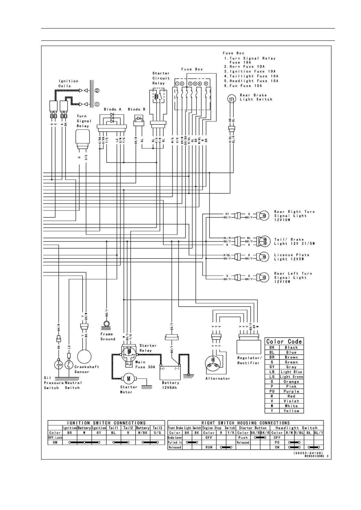
ELECTRICAL SYSTEM 16-13
Wiring Diagram (Indonesia and Philippines of the EX250J8 ∼ J9)
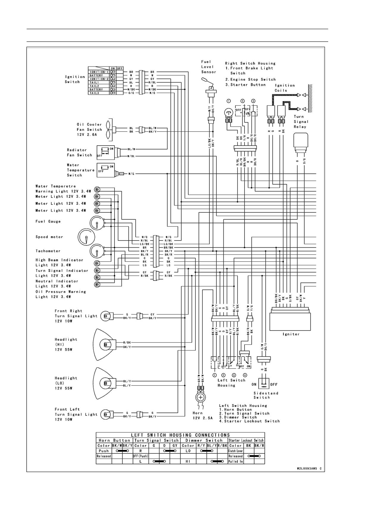
16-14 ELECTRICAL SYSTEM
Wiring Diagram (other than Indonesia and Philippines of the EX250JA ∼ JC)
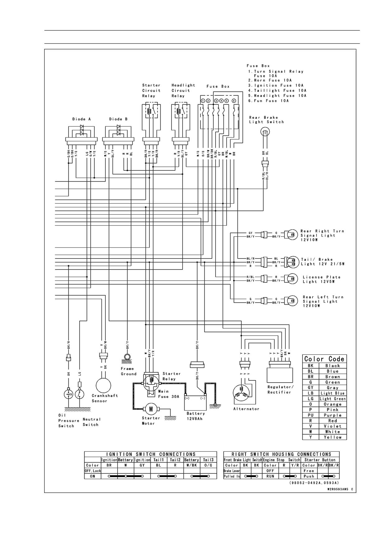
ELECTRICAL SYSTEM 16-15
Wiring Diagram (other than Indonesia and Philippines of the EX250JA ∼ JC)
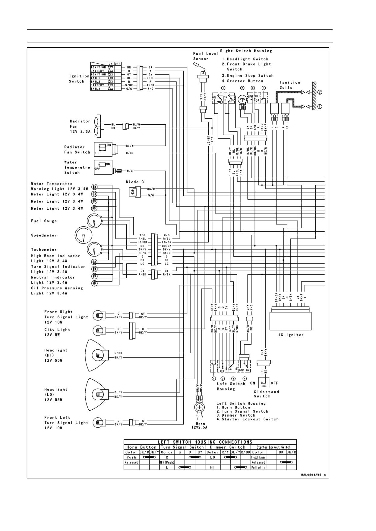
16-16 ELECTRICAL SYSTEM
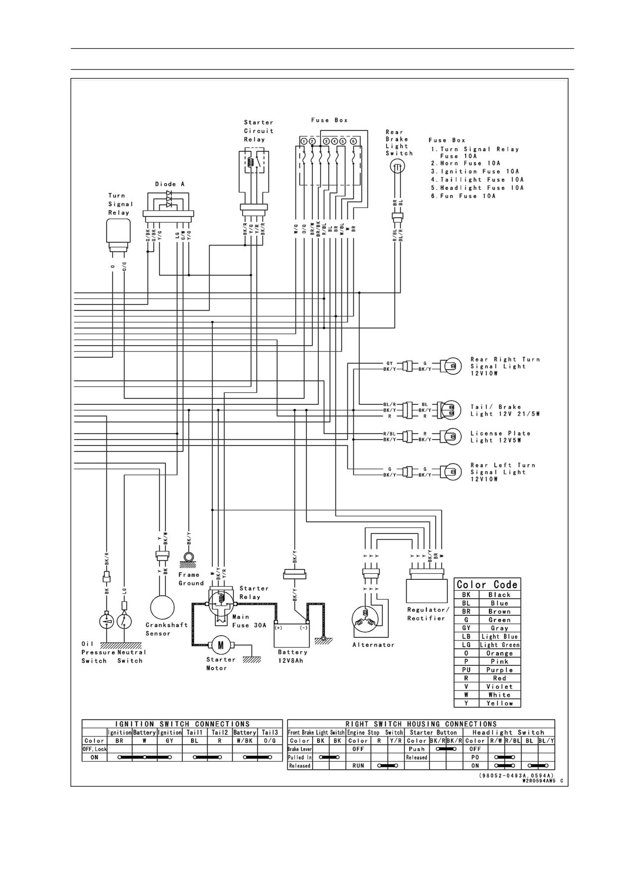
Wiring Diagram (Indonesia and Philippines of the EX250JA ∼ JC)
ELECTRICAL SYSTEM 16-17
Wiring Diagram (Indonesia and Philippines of the EX250JA ∼ JC)
16-18 ELECTRICAL SYSTEM
Specifications
Item
Standard
Service Limit
Battery
EX250J8:
Type
Sealed battery
- - -
Model Name
YTX7A-BS
- - -
Capacity
12 V 6 Ah
- - -
Voltage
12.8 V or more
- - -
EX250J9 ∼ JA:
Type
Sealed battery
- - -
Model Name
YTX9-BS
- - -
Capacity
12 V 8 Ah
- - -
Voltage
12.8 V or more
- - -
EX250JB ∼ JC:
Type
Sealed battery
- - -
Model Name
FTX9-BS
- - -
Capacity
12 V 8 Ah
- - -
Voltage
12-6 V or more
- - -
Charging System
Alternator Output Voltage
40 V or more @4 000 r/min (rpm)
- - -
Alternator Stator Coil Resistance
0.05 ∼ 0.6 Ω
- - -
Ignition System
Crankshaft Sensor Air Gap
0.7 mm (0.028 in.)
- - -
Crankshaft Sensor Resistance
100 ∼ 150 Ω
- - -
Ignition Coil:
3 Needle Arcing Distance
7 mm (0.28 in.) or more
- - -
Primary Winding Resistance
2.1 ∼ 2.5 Ω
- - -
Secondary Winding Resistance
10 ∼ 16 kΩ
- - -
Spark Plug Gap
0.7 ∼ 0.8 mm (0.028 ∼ 0.032 in.)
Electrical Stater System
Starter Motor:
Carbon Brush Length
10 mm (0.39 in.)
5 mm (0.20 in.)
Commutator Diameter
28 mm (1.10 in.)
27 mm (1.06 in.)
Switches and Sensors
Rear Brake Light Switch
ON after about 10 mm (0.39 in.) pedal
- - -
travel
Radiator Fan Switch connections:
Rising Temperature
From OFF to ON @95 ∼ 101°C (196 ∼
- - -
203°F)
Falling Temperature
From ON to OFF within 3 ∼ 8°C (37 ∼
- - -
46°F) of “ON” temperature
ON: less than 0.5 Ω
OFF: More than 1 MΩ
Water Temperature Switch
Connections:
Rising Temperature
From OFF to ON @112 ∼ 118°C (226
- - -
∼ 232°F)
ELECTRICAL SYSTEM 16-19
Specifications
Item
Standard
Service Limit
Falling Temperature
From ON to OFF @108°C (226°F) ∼
- - -
temperature less than ON
ON: Less than 0.5 Ω
OFF: More than 1 MΩ
16-20 ELECTRICAL SYSTEM
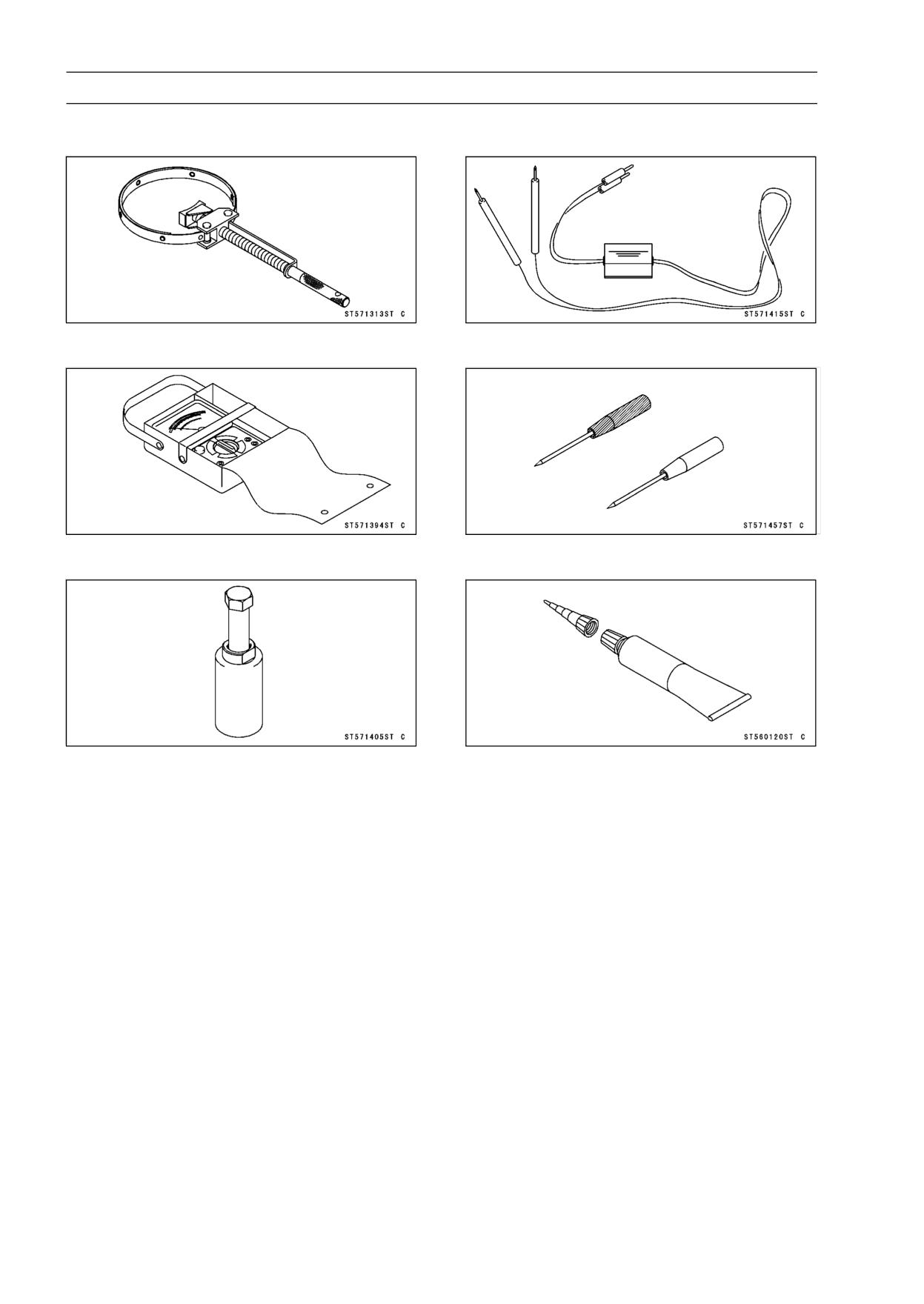
Special Tools and Sealant
Flywheel Holder:
Peak Voltage Adapter:
57001-1313
57001-1415
Hand Tester:
Needle Adapter Set:
57001-1394
57001-1457
Flywheel Puller Assembly, M38 × 1.5/M35 × 1.5:
Liquid Gasket, TB1211:
57001-1405
56019-120
ELECTRICAL SYSTEM 16-21
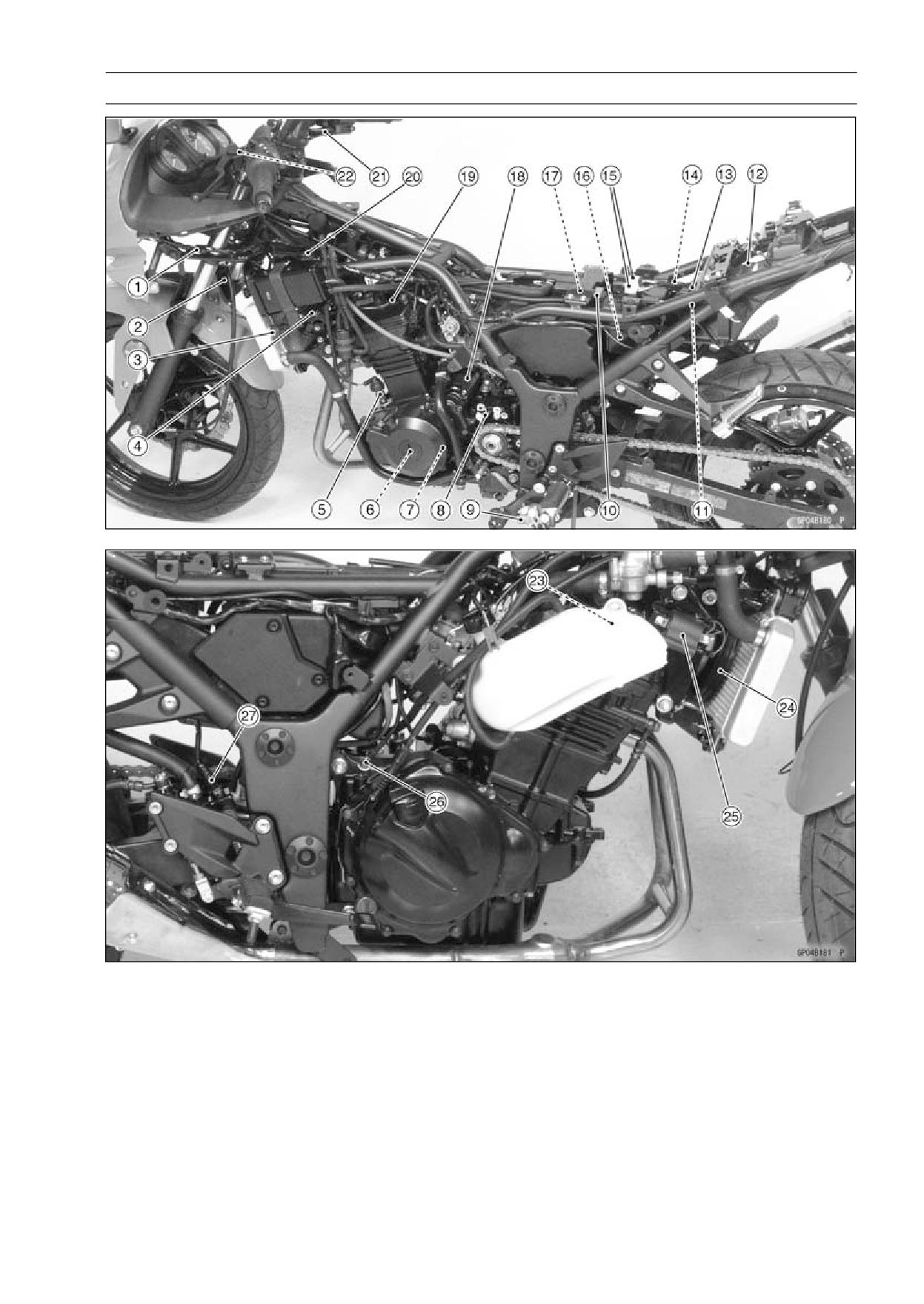
Parts Location
1. Diode
10. Main Fuse (30 A)
19. #1 Spark Plug
2. Horn
11. Fuse Box
20. Regulator/rectifier
3. Radiator Fan Switch
12. IC Igniter
21. Front Brake Light Switch
4. #1 Ignition Coil
13. Starter Circuit Relay
22. Starter Lockout Switch
5. Oil Pressure Switch
14. Headlight Circuit Relay
23. #2 Spark Plug
6. Alternator
15. Diodes
24. Radiator Fan
7. Crankshaft Sensor
16. Battery
25. #1 Ignition Coil
8. Neutral Switch
17. Starter Relay
26. Engine Ground Terminal
9. Sidestand Switch
18. Starter Motor
27. Rear Brake Light Switch
16-22 ELECTRICAL SYSTEM
Precautions
There are a number of important precautions that are
musts when servicing electrical systems. Learn and ob-
serve all the rules below.
○Do not reverse the battery lead connections. This will
burn out the diodes in the electrical parts.
○Always check battery condition before condemning other
parts of an electrical system. A fully charged battery is a
must for conducting accurate electrical system tests.
○The electrical parts should never be struck sharply, as
with a hammer, or allowed to fall on a hard surface. Such
a shock to the parts can damage them.
○To prevent damage to electrical parts, do not disconnect
the battery leads or any other electrical connections when
the ignition switch is on, or while the engine is running.
○Because of the large amount of current, never keep the
starter button pushed when the starter motor will not turn
over, or the current may burn out the starter motor wind-
ings.
○Do not use a meter illumination bulb rated for other than
voltage or wattage specified in the wiring diagram, as the
meter or gauge panel could be warped by excessive heat
radiated from the bulb.
○Take care not to short the leads that are directly con-
nected to the battery positive (+) terminal to the chassis
ground.
○Troubles may involve one or in some cases all items.
Never replace a defective part without determining what
CAUSED the failure. If the failure was caused by some
other item or items, they must be repaired or replaced, or
the new replacement will soon fail again.
○Make sure all connectors in the circuit are clean and tight,
and examine leads for signs of burning, fraying, etc. Poor
leads and bad connections will affect electrical system
operation.
○Measure coil and winding resistance when the part is cold
(at room temperature).
○Color Codes
BK: Black
G: Green
P: Pink
BL: Blue
GY: Gray
PU: Purple
BR: Brown
LB: Light blue
R: Red
CH: Chocolate
LG: Light green
W: White
DG: Dark green
O: Orange
Y: Yellow
○Electrical Connectors
Connectors [A]

ELECTRICAL SYSTEM 16-23
Precautions
Connectors [B]

16-24 ELECTRICAL SYSTEM
Electrical Wiring
Wiring Inspection
• Visually inspect the wiring for signs of burning, fraying,
etc.
If any wiring is in poor, replace the damaged wiring.
• Pull each connector [A] apart and inspect it for corrosion,
dirt, and damage.
If the connector is corroded or dirty, clean it carefully. If it
is damaged, replace it.
• Check the wiring for continuity.
○Use the wiring diagram to find the ends of the lead which
is suspected of being a problem.
○Connect the hand tester between the ends of the leads.
Special Tool - Hand Tester: 57001-1394
○Set the tester to the × 1 Ω range, and read the meter.
If the tester does not read 0 Ω, the lead is defective. Re-
place the lead or the wiring harness [B] if necessary.
ELECTRICAL SYSTEM 16-25
Battery
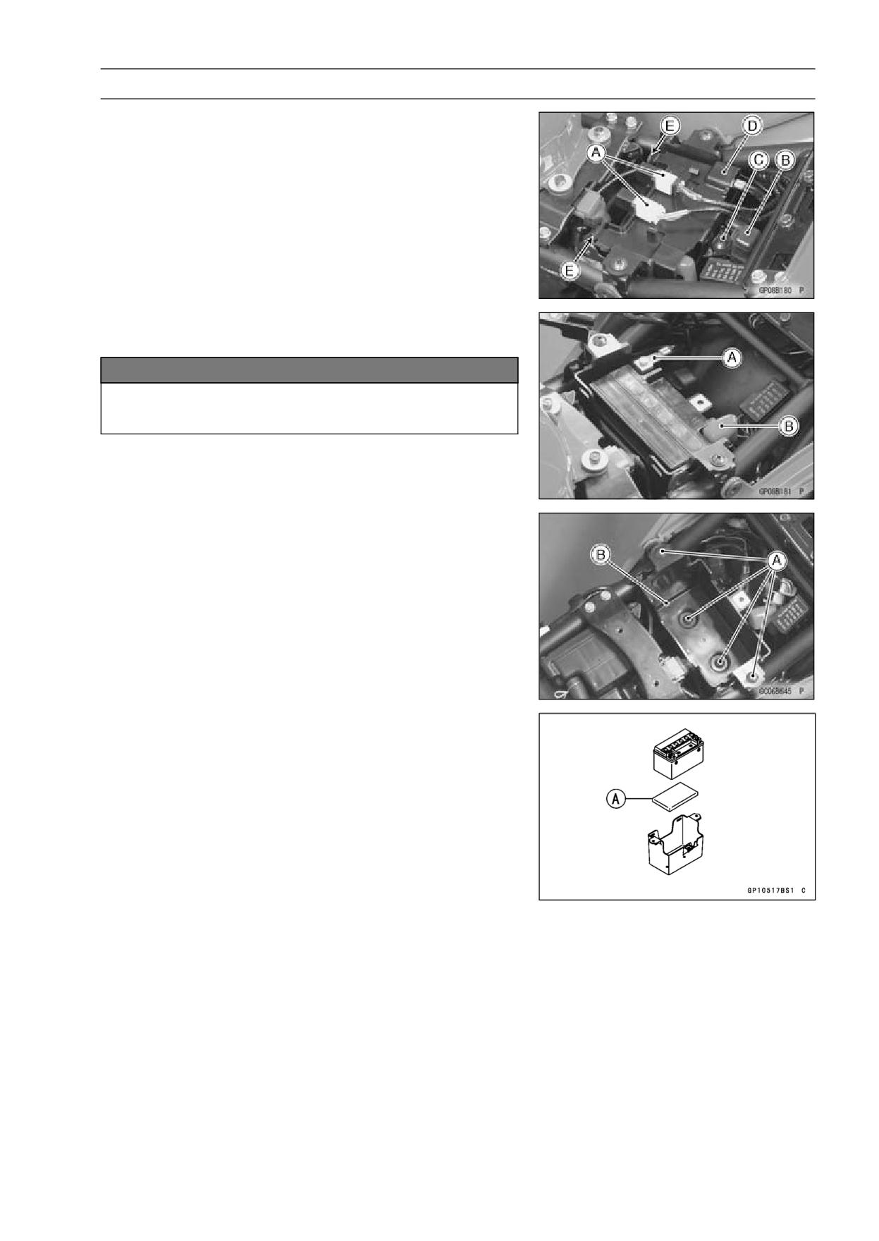
Battery Removal
• Pull the diodes [A] and headlight circuit relay [B] out of the
cover.
• Unscrew the screw [C] and remove the cover [D], clearing
the projections [E].
• Disconnect the negative (-) cable [A] and then the positive
(+) cable [B].
NOTICE
Be sure to the disconnect the negative (-) cable
first.
• Remove the battery.
• To remove the battery case [B], remove the screws [A].
Battery Installation
• Be sure the battery damper [A] is in position.
• Connect the positive (+) cable first, then the negative (-)
cable to the battery.
16-26 ELECTRICAL SYSTEM
Battery
Battery Activation
Electrolyte Filling
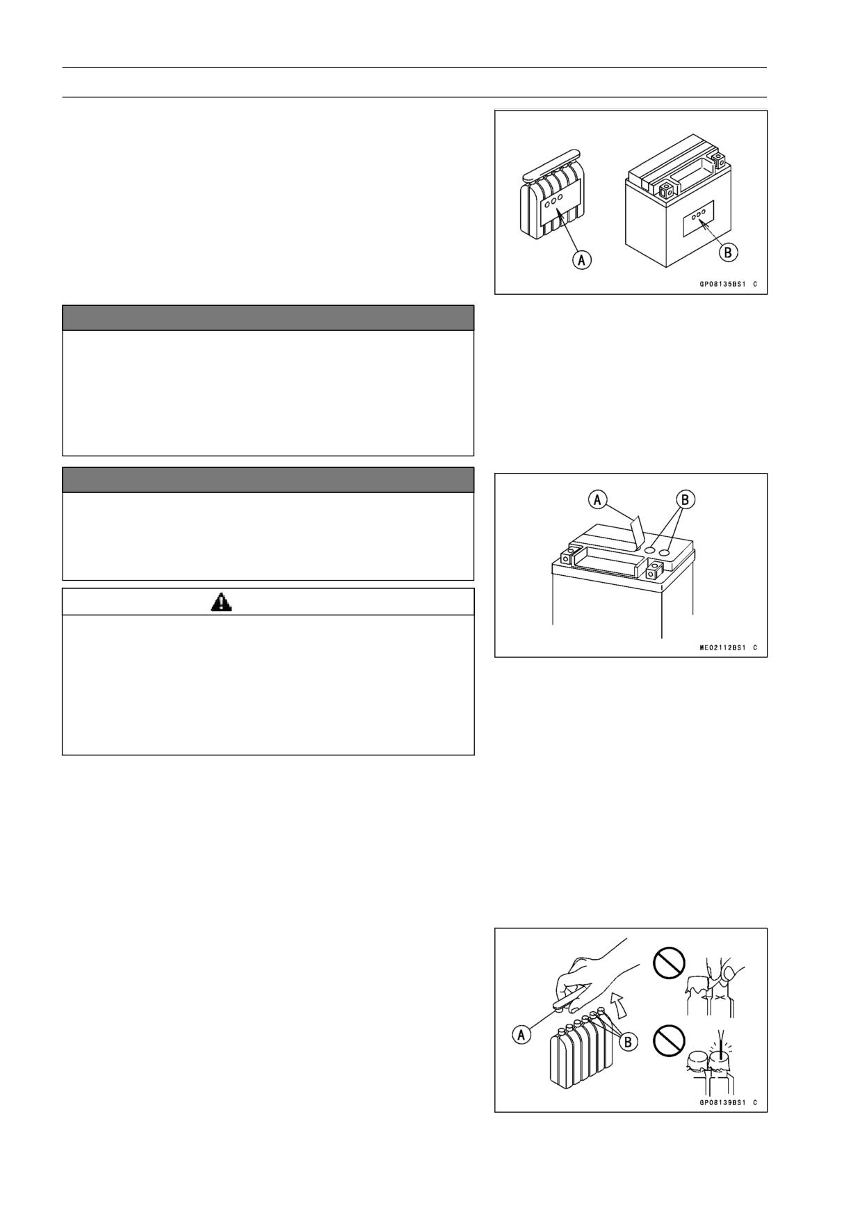
• Make sure that the model name [A] of the electrolyte con-
tainer matches the model name [B] of the battery. These
names must be the same.
Battery Model Name
EX250J8: YTX7A-BS
EX250J9 ∼ JA : YTX9-BS
EX250JB ∼ JC: FTX9-BS
NOTICE
Be sure to use the electrolyte container with the
same model name as the battery since the elec-
trolyte volume and specific gravity vary with the
battery type. This is to prevent overfilling of the
electrolyte, shorting the battery life, and deteriora-
tion of the battery performance.
NOTICE
Do not remove the aluminum sealing sheet [A] from
the filler ports [B] until just prior to use. Be sure to
use the dedicated electrolyte container for correct
electrolyte volume.
WARNING
The electrolyte contains sulfuric acid, which can
cause severe burns. To avoid sulfuric acid burns,
wear protective clothing and safety glasses when
handling electrolyte. If the electrolyte touches the
skin or eyes, wash the area with liberal amounts of
water and seek medical attention for more severe
burns.
• Place the battery on a level surface.
• Check to see that the sealing sheet has no peeling, tears,
or holes in it.
• Remove the sealing sheet.
NOTE
○The battery is vacuum sealed. If the sealing sheet has
leaked air into the battery, it may require a longer initial
charge.
• Remove the electrolyte container from the vinyl bag.
• Detach the strip of caps [A] from the container and set
aside, these will be used later to seal the battery.
NOTE
○Do not pierce or otherwise open the sealed cells [B] of
the electrolyte container. Do not attempt to separate
individual cells.
ELECTRICAL SYSTEM 16-27
Battery
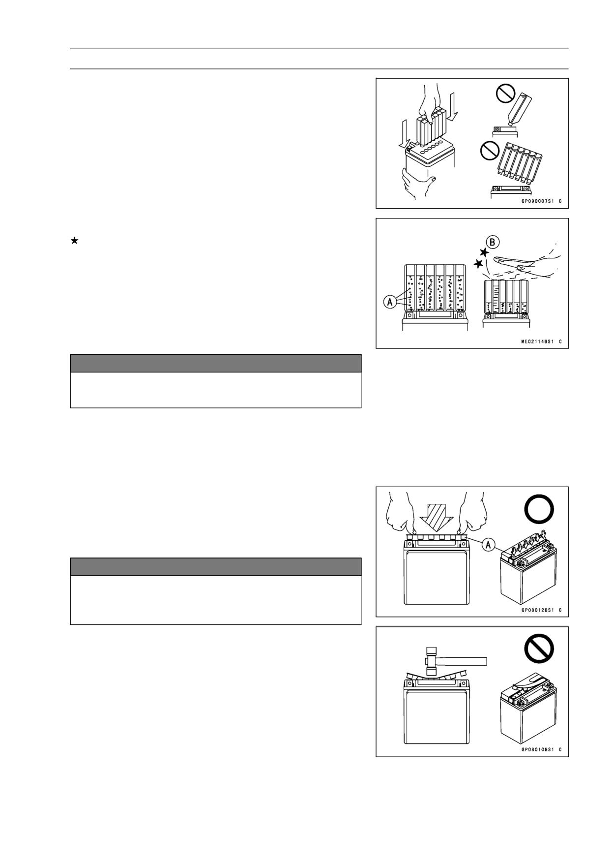
• Place the electrolyte container upside down with the six
sealed cells into the filler ports of the battery. Hold the
container level, push down to break the seals of all six
cells. You will see air bubbles rising into each cell as the
ports fill.
NOTE
○Do not tilt the electrolyte container.
• Check the electrolyte flow.
If no air bubbles [A] are coming up from the filler ports, or
if the container cells have not emptied completely, tap the
container [B] a few times.
NOTE
○Be careful not to have the battery fall down.
• Keep the container in place. Don’t remove the container
from the battery, the battery requires all the electrolyte
from the container for proper operation.
NOTICE
Removal of the container before it is completely
empty can shorten the service life of the battery.
• After filling, let the battery sit for 20 ∼ 60 minutes with the
electrolyte container kept in place, which is required for
the electrolyte to fully permeate into the plates.
• Make sure that the container cells have emptied com-
pletely, and remove the container from the battery.
• Place the strip of caps [A] loosely over the filler ports,
press down firmly with both hands to seat the strip of caps
into the battery (don’t pound or hammer). When properly
installed, the strip of caps will be level with the top of the
battery.
NOTICE
Once the strip of caps is installed onto the battery,
never remove the caps, nor add water or electrolyte
to the battery.
NOTE
○Charging the battery immediately after filling can
shorten service life.
16-28 ELECTRICAL SYSTEM
Battery
Initial Charge
• Newly activated sealed batteries require an initial charge.
YTX7A-BS
Standard Charge:
0.7 A × 5 ∼ 10 hours
YTX9-BS/FTX9-BS
Standard Charge:
0.9 A × 5 ∼ 10 hours
If using a recommended battery charger, follow the
charger’s instructions for newly activated sealed battery.
Kawasaki-recommended chargers:
Battery Mate 150-9
OptiMate PRO 4-S/PRO S/PRO2
Yuasa MB-2040/2060
Christie C10122S
If the above chargers are not available, use equivalent
one.
• Let battery sit 30 minutes after initial charge, then check
voltage using a voltmeter. (Voltage immediately after
charging becomes temporarily high. For accurate mea-
suring, let the battery sit for given time.)
NOTE
○Charging rates will vary depending on how long the
battery has been stored, temperature, and the type of
charger used. If voltage is not at least 12.8 V (FTX9-BS:
12.6V), repeat charging cycle.
○To ensure maximum battery life and customer satisfac-
tion, it is recommended the battery be load tested at
three times its amp-hour rating for 15 seconds.
Re-check voltage and if less than 12.8 V (FTX9-BS:
12.6V) repeat the charging cycle and load test. If still
below 12.8 V (FTX9-BS: 12.6V) the battery is defective.
Precautions
1) No need of topping-up
No topping-up is necessary in this battery until it ends its life under normal use. Forcibly prying off the
seal cap to add water is very dangerous. Never do that.
2) Refreshing charge
If an engine will not start, a horn sounds weak, or lamps are dim, it indicates the battery has been
discharged. Give refresh charge for 5 to 10 hours with charge current shown in the specification
(see this chapter).
When a fast charge is inevitably required, do it following precisely the maximum charge current
and time conditions indicated on the battery.
NOTICE
This battery is designed to sustain no unusual deterioration if refresh-charged according
to the method specified above. However, the battery’s performance may be reduced no-
ticeably if charged under conditions other than given above. Never remove the seal cap
during refresh charge.
If by chance an excessive amount of gas is generated due to overcharging, the relief valve
releases the gas to keep the battery normal.
3) When you do not use the motorcycle for months:
Give a refresh charge before you store the motorcycle and store it with the negative cable re-
moved. Give a refresh charge once a month during storage.
ELECTRICAL SYSTEM 16-29
Battery
4) Battery life:
If the battery will not start the engine even after several refresh charges, the battery has ex-
ceeded its useful life. Replace it (Provided, however, the vehicle’s starting system has no prob-
lem).
DANGER
Batteries produce an explosive gas mixture of hydrogen and oxygen that can cause seri-
ous injury and burns if ignited. Keep the battery away from sparks and open flames during
charging. When using a battery charger, connect the battery to the charger before turning
on the charger. This procedure prevents sparks at the battery terminals which could ignite
any battery gases. The electrolyte contains sulfuric acid. Be careful not to have it touch
your skin or eyes. If touched, wash it off with liberal amount of water and seek medial at-
tention for more severe burns.
Interchange
A sealed battery can fully display its performance only when combined with a proper vehicle electric
system. Therefore, replace a sealed battery only on a motorcycle which was originally equipped with
a sealed battery.
Be careful, if a sealed battery is installed on a motorcycle which had an ordinary battery as original
equipment, the sealed battery’s life will be shortened.
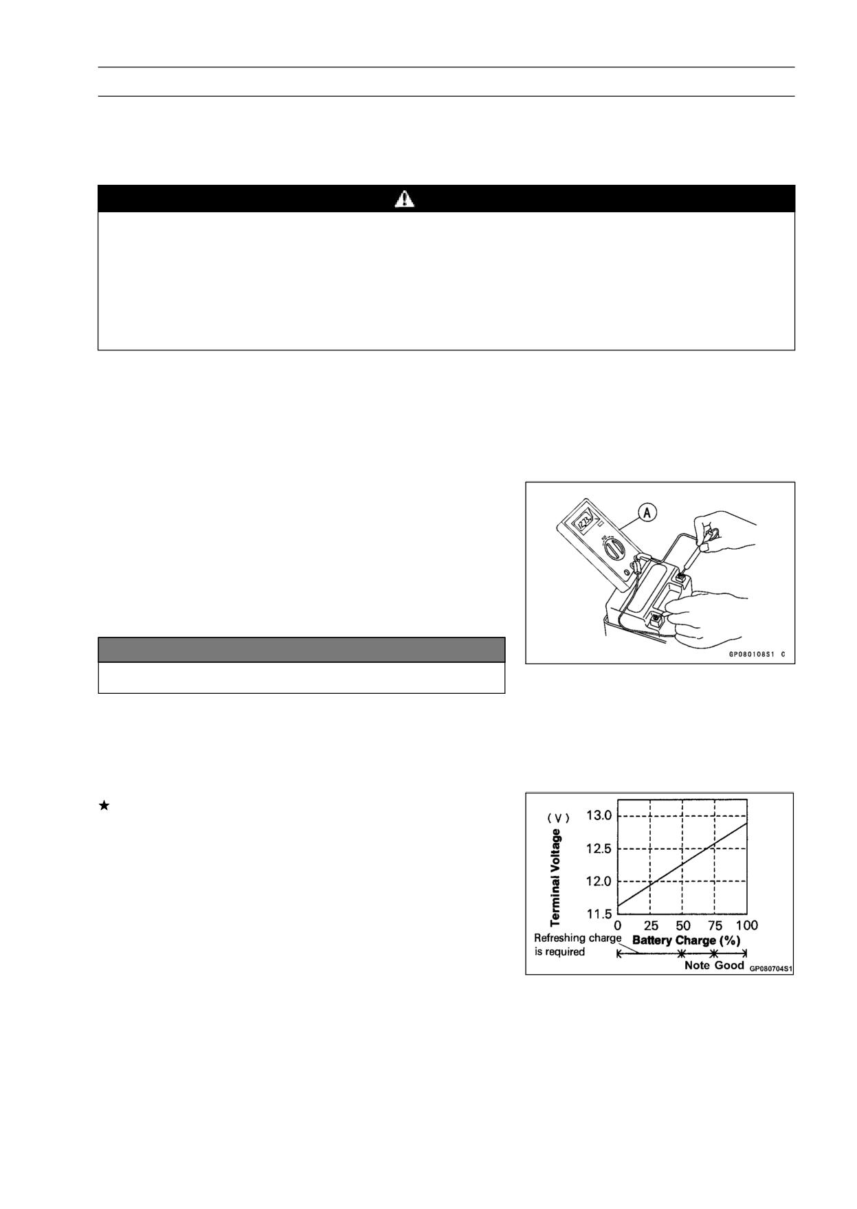
Charging Condition Inspection
○Battery charging condition can be checked by measuring
battery terminal voltage with a digital voltmeter [A].
• Remove:
Front Seat (see Front Seat Removal in the Frame chap-
ter)
Battery Cover
• Disconnect the battery terminals.
NOTICE
Be sure to disconnect the negative (-) cable first.
• Measure the battery terminal voltage.
NOTE
○Measure with a digital voltmeter which can be read one
decimal place voltage.
If the reading is 12.8 V or more, no refresh charge is re-
quired, however, if the read is below the specified, refresh
charge is required.
Battery Terminal Voltage
Standard:
12.8 V or more
16-30 ELECTRICAL SYSTEM
Battery
Refreshing Charge
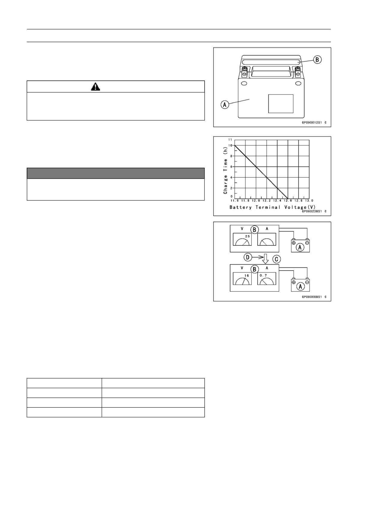
• Remove the battery [A] (see Battery Removal).
• Do refresh charge by following method according to the
battery terminal voltage.
WARNING
This battery is a sealed type. Never remove sealing
cap [B] even at charging. Never add water. Charge
with current and time as stated below.
Terminal Voltage: 11.5 ∼ less than 12.8 V
Standard Charge:
0.7 A × 5 ∼ 10 h (see following chart)
Quick Charge:
4A ×1 h
NOTICE
If possible, do not quick charge. If quick charge is
done unavoidably, do standard charge later on.
Terminal Voltage: less than 11.5 V
Charging Method:
0.7 A × 20 h
NOTE
○Increase the charging voltage to a maximum voltage of
25 V if the battery will not accept current initially. Charge
for no more than 5 minutes at the increased voltage then
check if the battery is drawing current. If the battery
will accept current decrease the voltage and charge by
the standard charging method described on the battery
case. If the battery will not accept current after 5 min-
utes, replace the battery.
Battery [A]
Battery Charger [B]
Standard Value [C]
Current starts to flow [D]
• Determine the battery condition after refresh charge.
○Determine the condition of the battery left for 30 minutes
after completion of the charge by measuring the terminal
voltage according to the table below.
Criteria
Judgement
12.8 V or higher
Good
12.0 ∼ lower than 12.8 V
Charge insufficient → Recharge
lower than 12.0 V
Unserviceable → Replace
ELECTRICAL SYSTEM 16-31
Charging System
Alternator Cover Removal
• Drain:
Engine Oil (see Engine Oil Change in the Periodic Main-
tenance chapter)
Coolant (see Coolant Change in the Periodic Mainte-
nance chapter)
• Remove:
Left Lower Fairing (see Lower Fairing Removal in the
Frame chapter)
Shift Lever Link
Engine Sprocket Cover
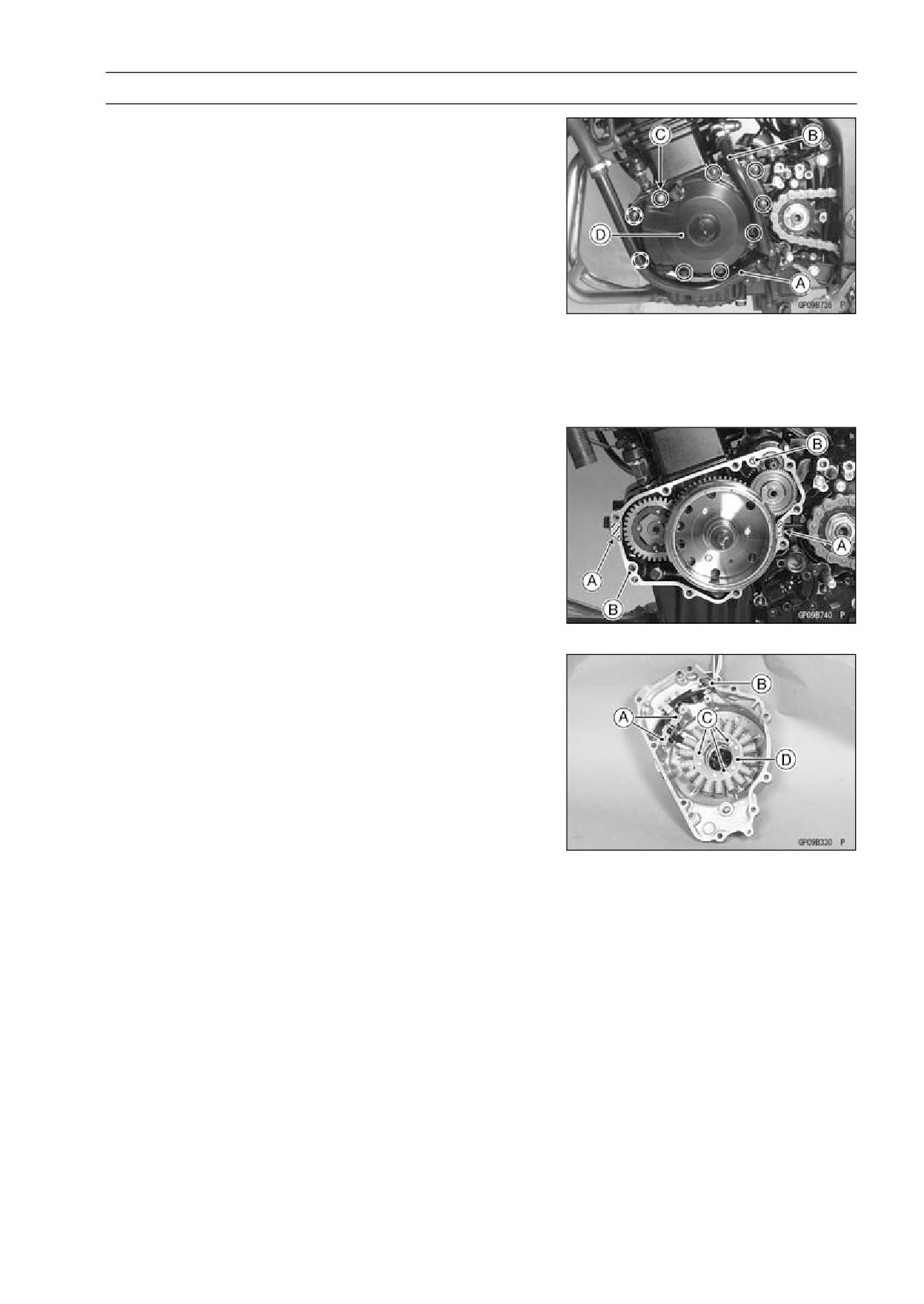
Coolant Pipes [A], [B]
• Remove:
Alternator Cover Bolts [C]
Alternator Cover [D]
Alternator Cover Installation
• Apply liquid gasket to the alternator lead grommet and
crankcase halves mating surface [A] on the front and rear
side of the cover mount.
Sealant - Liquid Gasket, TB1211: 56019-120
• Check that the knock pins [B] are in place on the
crankcase.
• Install a new gasket and the alternator cover.
Torque - Water Hose Clamp Screws: 3.0 N·m (0.31 kgf·m,
27 in·lb)
Stater Coil Removal
• Remove:
Alternator Cover (see Alternator Cover Removal)
Crankshaft Sensor Screws [A] and Clamps
Alternator Lead Grommet [B]
Stator Coil Bolts [C]
• Remove the stator coil [D] from the alternator cover.
16-32 ELECTRICAL SYSTEM
Charging System
Stator Coil Installation
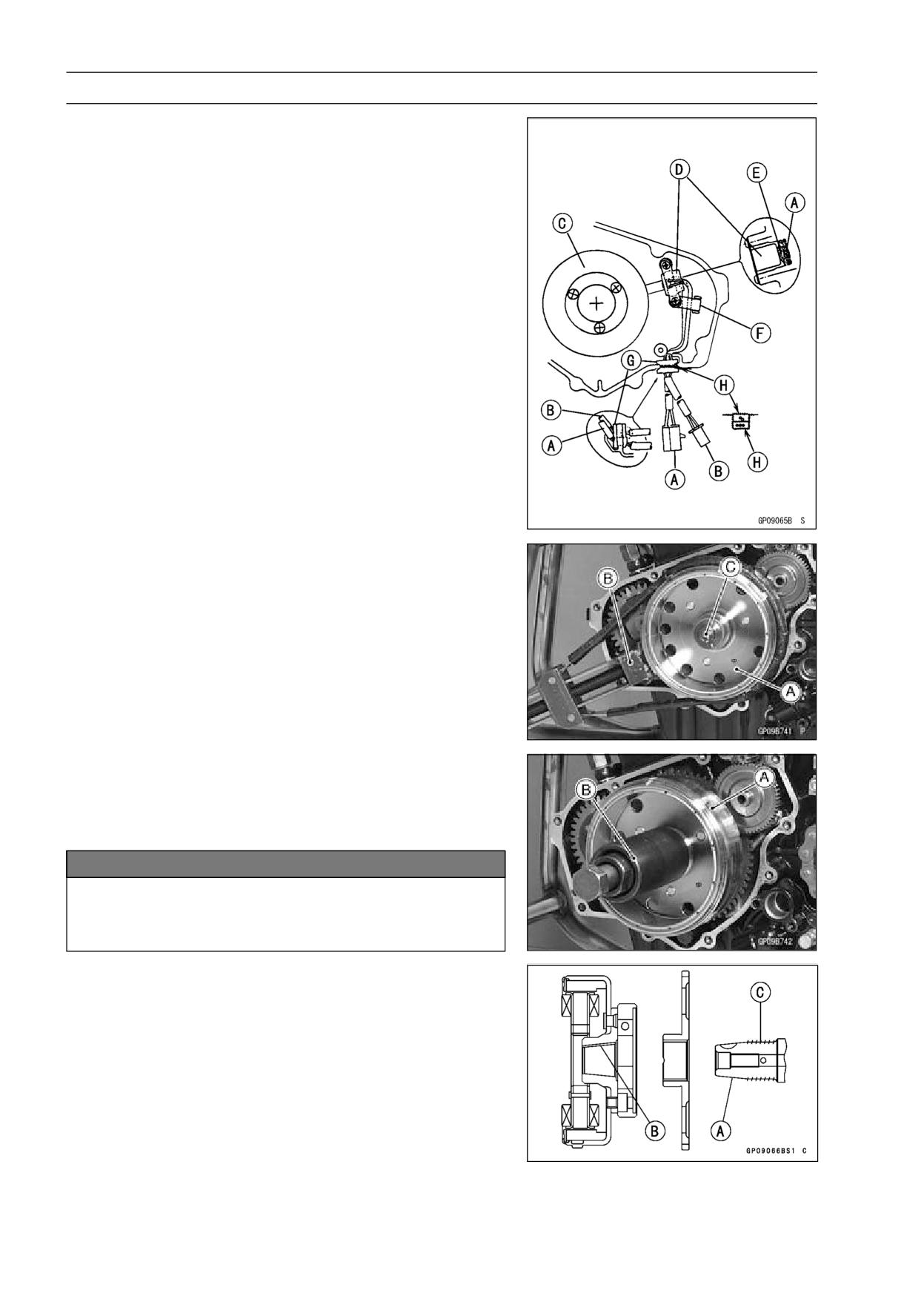
• Install the alternator leads [A] and crankshaft sensor leads
[B] into the alternator cover as figure.
Stator Coil [C]
Crankshaft Sensor Coil [D]
Rubber Damper [E]
Clamp [F]
Grommet [G]
Silicone Sealant Applied Areas [H]
○Fit the alternator leads and crankshaft sensor leads into
the grommet.
○Apply liquid gasket to the grommet, and fit it into the notch
in the alternator cover.
Sealant - Liquid Gasket, TB1211: 56019-120
• Install the crankshaft sensor.
• Clamp the harness of the crankshaft sensor leads.
• Tighten the stator bolts with the specified torque.
Torque - Alternator Stator Bolts:
12 N·m (1.2 kgf·m, 104
in·lb)
Alternator Rotor Removal
• Remove the alternator cover (see Alternator Cover Re-
moval).
• Hold the alternator rotor [A] steady with the flywheel
holder [B], and remove the rotor bolt [C].
Special Tool - Flywheel Holder: 57001-1313
• Remove the rotor [A] using the flywheel puller assembly
[B].
Special Tool - Flywheel Puller Assembly, M38 × 1.5/M35 ×
1.5: 57001-1405
NOTICE
Do not attempt to strike the alternator rotor itself.
Striking the rotor can cause the magnets to lose
their magnetism.
Alternator Rotor Installation
• Using a cleaning fluid, clean off any oil or dirt on the fol-
lowing portions, and dry them with a clean cloth.
Crankshaft Tapered Portion [A]
Alternator Rotor Tapered Portion [B]
• Apply a thin coat of molybdenum disulfide grease to the
crankshaft [C].
ELECTRICAL SYSTEM 16-33
Charging System
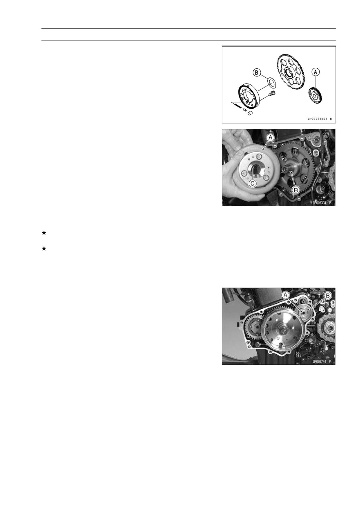
• Install the starter gear [A] and washer [B].
• Again, clean the crankshaft tapered portion and dry there.
• Install the alternator rotor [A] while turning it counterclock-
wise to make easy to align the key [B] and key groove [C]
of the rotor.
NOTE
○Confirm the alternator rotor fit or not to the crankshaft
before tighten it with the specified torque.
○Install the rotor bolt and tighten it with 55 N·m (5.6 kgf·m,
41 ft·lb) of torque.
○Remove the rotor bolt.
○Check the tightening torque with flywheel puller.
If the rotor is not pulled out with 20 N·m (2.0 kgf·m, 14.5
ft·lb) of drawing torque, it is installed correctly.
If the rotor is pulled out with 20 N·m (2.0 kgf·m, 14.5 ft·lb)
of drawing torque, clean off any oil dirt or flaw of the crank-
shaft and rotor tapered portion and dry them with a clean
cloth. Then, confirm that it is not pulled out with above
torque.
• Tighten the alternator rotor bolt with holding the alternator
rotor steady with the flywheel holder.
Special Tool - Flywheel Holder: 57001-1313
Torque - Alternator Rotor Bolt: 88.2 N·m (9.0 kgf·m, 65 ft·lb)
• Apply a thin coat of molybdenum disulfide grease to the
shaft [A], and install it and starter idle gear [B].
• Install the alternator cover (see Alternator Cover Installa-
tion).
Alternator Inspection
There are three types of alternator failures: short, open
(wire burned out), or loss in rotor magnetism. A short or
open in one of the coil wires will result in either a low output,
or no output at all. A loss in rotor magnetism, which may be
caused by dropping or hitting the alternator, by leaving it
near an electromagnetic field, or just by aging, will result in
low output.
• To check the alternator output voltage, do the following
procedures.
○Turn off the ignition switch.
○Remove the right side cover (see Side Cover Removal in
the Frame chapter).
16-34 ELECTRICAL SYSTEM
Charging System
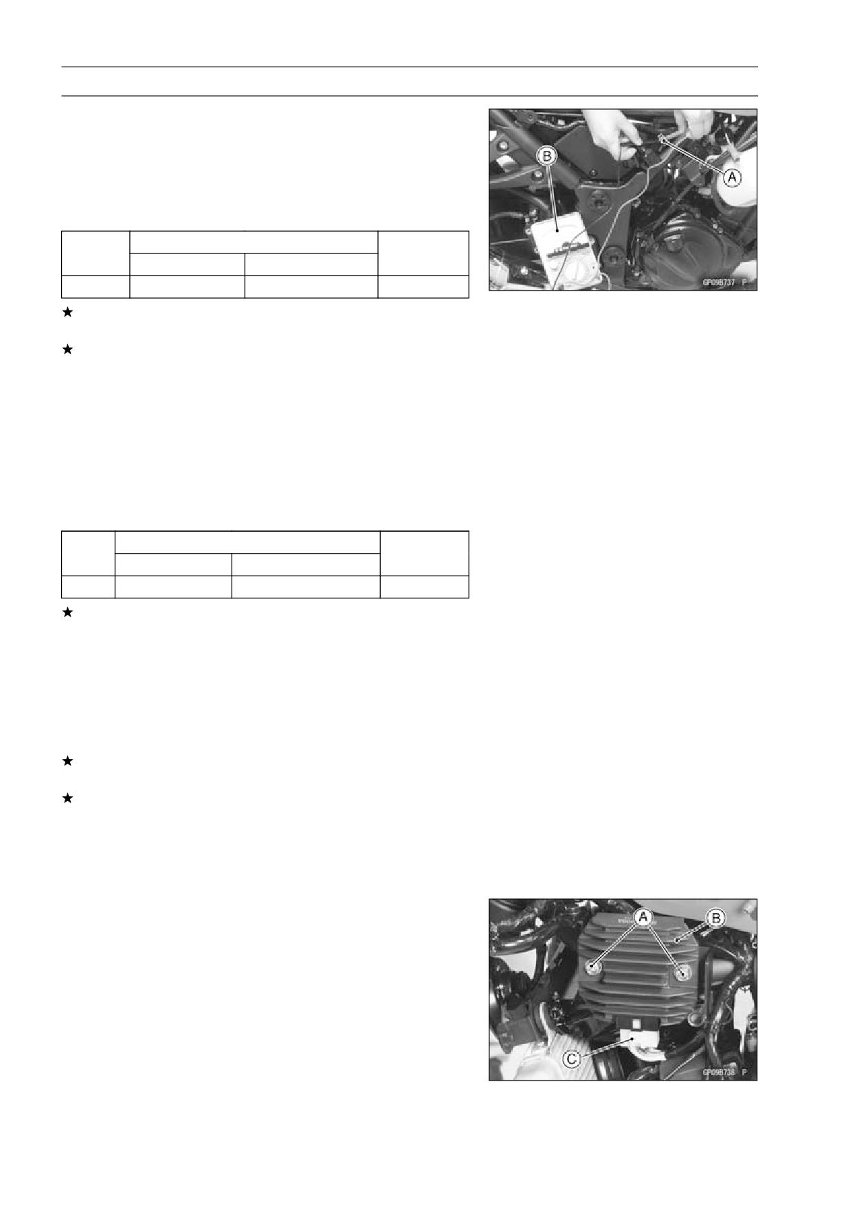
○Disconnect the alternator lead connector [A].
○Connect the hand tester [B]as shown in the table 1.
○Start the engine, and run it 4 000 rpm 5 minutes.
○Run it at the rpm given in the table 1.
○Note the voltage readings (total 3 measurements).
Table 1 Alternator Output Voltage
Tester
Connections
Reading
Range
Tester (+) to
Tester (-) to
@4 000 rpm
250 V AC
One Yellow lead
Another Yellow lead
about 40 V
If the output voltage shows the value in the table, the al-
ternator operates properly.
If the output voltage shows a much higher than the value
in the table, the regulator/rectifier is damaged. A much
lower reading than that given in the table indicates that
the alternator is defective.
• Check the stator coil resistance as follows.
○Stop the engine.
○Connect the hand tester as shown in the table 2.
○Note the readings (total 3 measurement).
Table 2 Stator Coil Resistance
Tester
Connections
Reading
Range
Tester (+) to
Tester (-) to
×1Ω
One Yellow lead
Another Yellow lead
0.05 ∼ 0.6 Ω
If there is more resistance than shown in the table, or no
hand tester reading (infinity) for any two leads, the stator
has an open lead and must be replaced. Much less than
this resistance means the stator is shorted, and must be
replaced.
• Using the highest resistance range of the hand tester,
measure the resistance between each of the black leads
and chassis ground.
Any hand tester reading less than infinity (∞) indicates a
short, necessitating stator replacement.
If the stator coils have normal resistance, but the voltage
check showed the alternator to be defective; then the rotor
magnets have probably weakened, and the rotor must be
replaced.
Special Tool - Hand Tester: 57001-1394
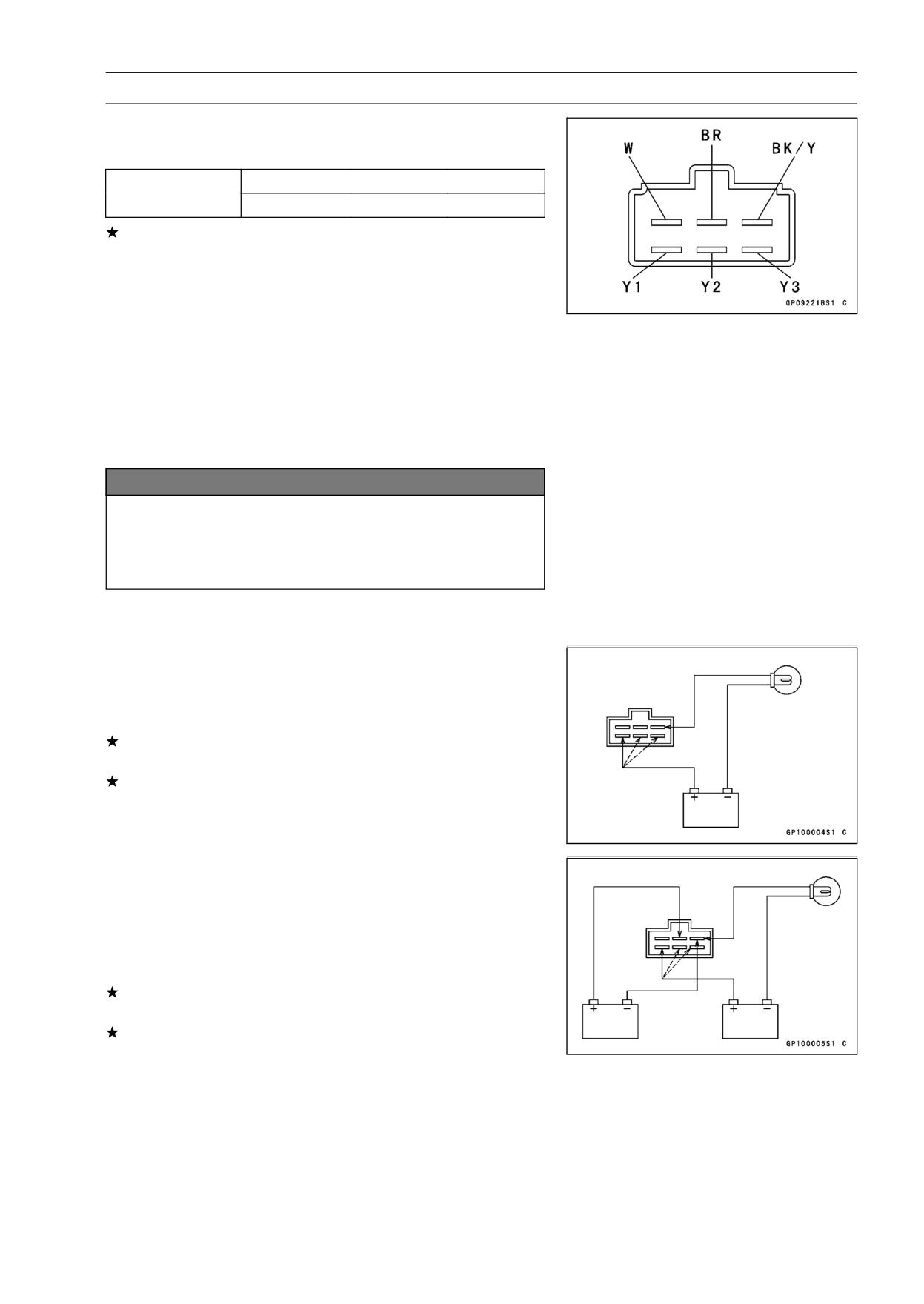
Regulator/Rectifier Inspection
• Remove:
Right Lower Fairing (see Lower Fairing Removal in the
Frame chapter)
Bolts [A]
Regulator/Rectifier [B]
Connector [C] (Disconnect)
ELECTRICAL SYSTEM 16-35
Charging System
• Check conductivity of the following pair of terminals.
Rectifier Circuit Inspection
W-Y1,
W-Y2,
W-Y3
Tester connection
BK/Y-Y1,
BK/Y-Y2,
BK/Y-Y3
The resistance should be low in one direction and more
than ten times as much in the other direction. If any two
leads are low or high in both directions, the rectifier is
defective and the regulator/rectifier must be replaced.
NOTE
○The actual meter reading varies with the meter used
and the individual rectifier, but, generally speaking the
lower reading should be from zero to one half the scale.
Regulator Circuit Check
To test the regulator out of circuit, use three 12 V batteries
and a test light (12 V 3 ∼ 6 W bulb in a socket with leads).
NOTICE
The test light works as an indicator and also a cur-
rent limiter to protect the regulator/rectifier from ex-
cessive current. Do not use an ammeter instead of
a test light.
• Check to be sure the rectifier circuit is normal before con-
tinuing.
• Do the 1st step regulator circuit test.
○Connect the test light and the 12 V battery to the regula-
tor/rectifier as shown.
○Check the Y1, Y2 and Y3 terminal respectively.
If the test light turns on, the regulator/rectifier is defective.
Replace it.
If the test light does not turn on, continue the test.
• Do the 2nd step regulator circuit test.
○Connect the test light and the 12 V battery in the same
manner as specified in the “Regulator Circuit Test-1st
Step”.
○Apply 12 V to the voltage BR terminal.
○Check the Y1, Y2 and Y3 terminal respectively.
If the test light turns on, the regulator/rectifier is defective.
Replace it.
If the test light does not turn on, continue the test.
16-36 ELECTRICAL SYSTEM
Charging System
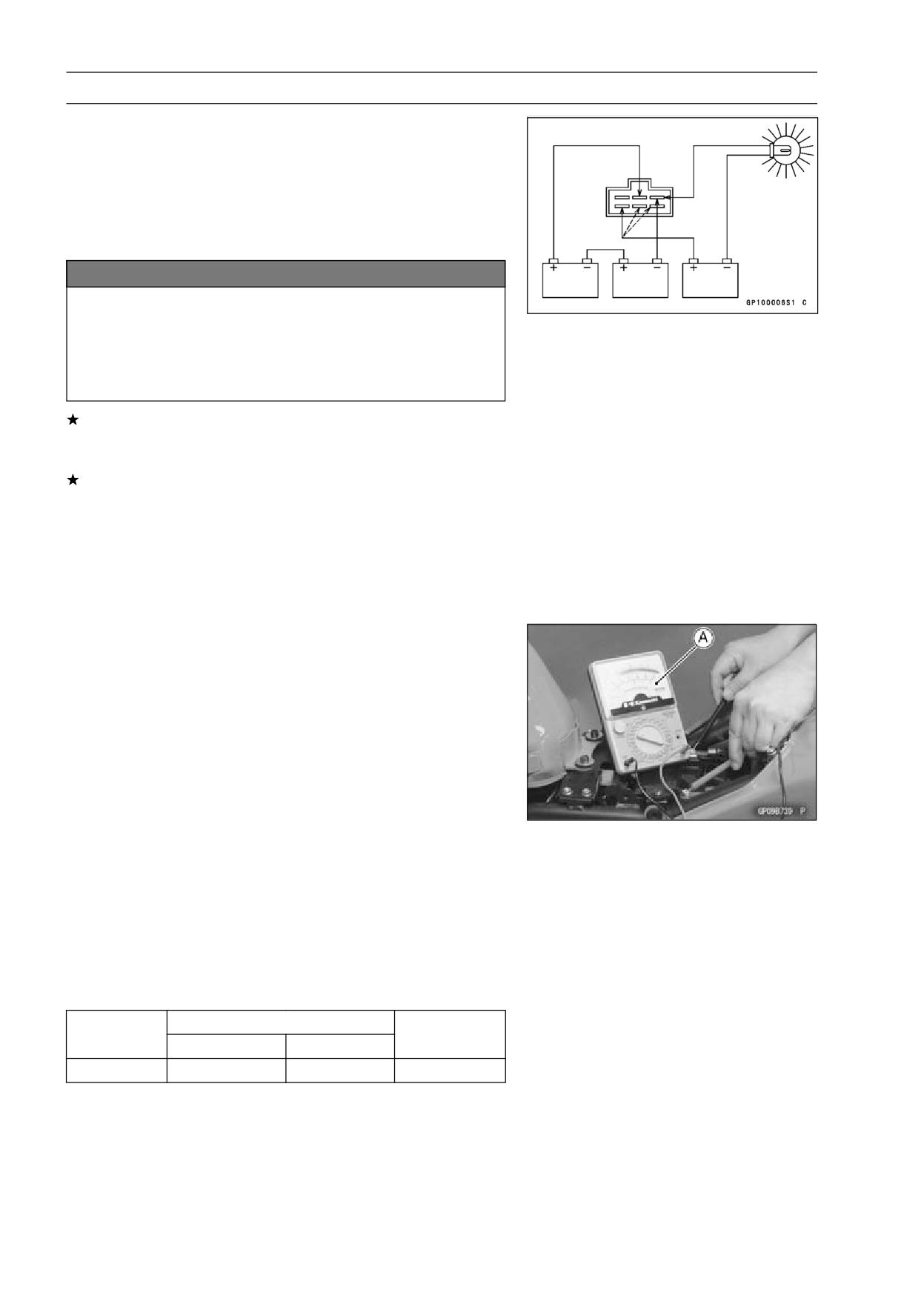
• Do the 3rd step regulator circuit test.
○Connect the test light and the 12 V battery in the same
manner as specified in the “Regulator Circuit Test-1st
Step”.
○Momentarily apply 24 V to the voltage BR terminal by
adding a 12 V battery.
○Check the Y1, Y2 and Y3 terminals respectively.
NOTICE
Do not apply more than 24 V. If more than 24 V is ap-
plied, the regulator/rectifier may be damaged. Do
not apply 24 V more than a few seconds. If 24 V
is applied for more than a few seconds, the regula-
tor/rectifier may be damaged.
If the test light did not light when the 24 V was applied
momentarily to the voltage monitoring terminal, the regu-
lator/rectifier is defective. Replace it.
If the regulator/rectifier passes all of the tests described,
it may still be defective. If the charging system still does
not work properly after checking all of the components
and the battery, test the regulator/rectifier by replacing it
with a known good unit.
Torque - Regulator/Rectifier Bolts: 9.8 N·m (1.0 kgf·m, 87
in·lb)
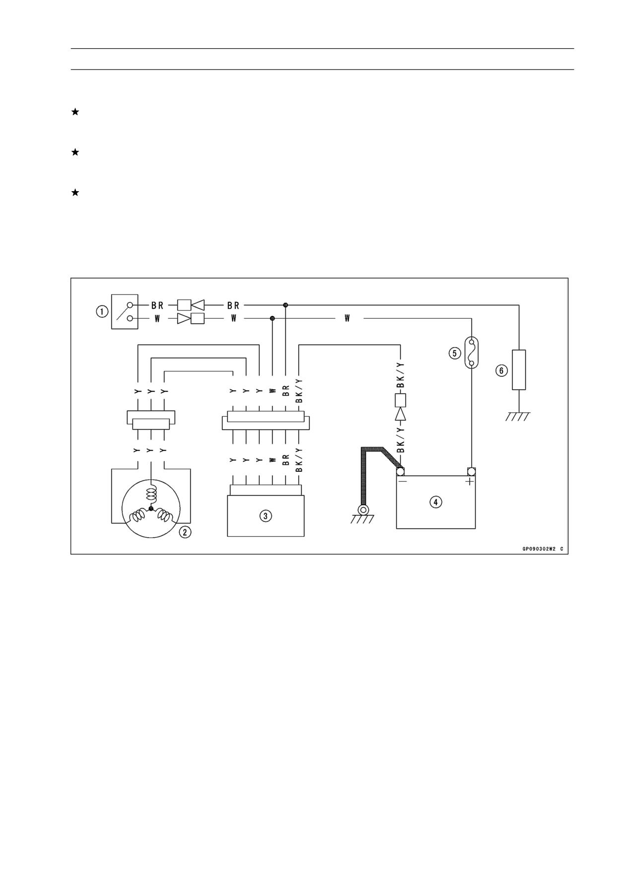
Charging Voltage Inspection
• Check the battery condition (see Charging Condition In-
spect).
• Warm up the engine to obtain actual alternator operating
conditions.
• Remove the front seat (see Front Seat Removal in the
Frame chapter).
• Check that the ignition switch is turned off, and connect
the hand tester [A] as shown in the table.
Special Tool - Hand Tester: 57001-1394
• Start the engine, and note the voltage readings at vari-
ous engine speeds with the headlight turned on and then
turned off. (To turn off the headlight, disconnect the head-
light connector in the upper fairing.) The readings should
show nearly battery voltage when the engine speed is low,
and, as the engine speed rises, the readings should also
rise. But they must be kept under the specified voltage.
Charging Voltage
Connections
Tester Range
Reading
Tester (+) to
Tester (-) to
25 V DC
Battery (+)
Battery (-)
14 ∼15 V
ELECTRICAL SYSTEM 16-37
Charging System
• Turn off the ignition switch to stop the engine, and discon-
nect the hand tester.
If the charging voltage is kept between the values given in
the table, the charging system is considered to be working
normally.
If the charging voltage is much higher than the values
specified in the table, the regulator/rectifier is defective
or the regulator/rectifier leads are loose or open.
If the charging voltage does not rise as the engine speed
increases, then the regulator/rectifier is defective or the
alternator output is insufficient for the loads. Check the
alternator and regulator/rectifier to determine which part
is defective.
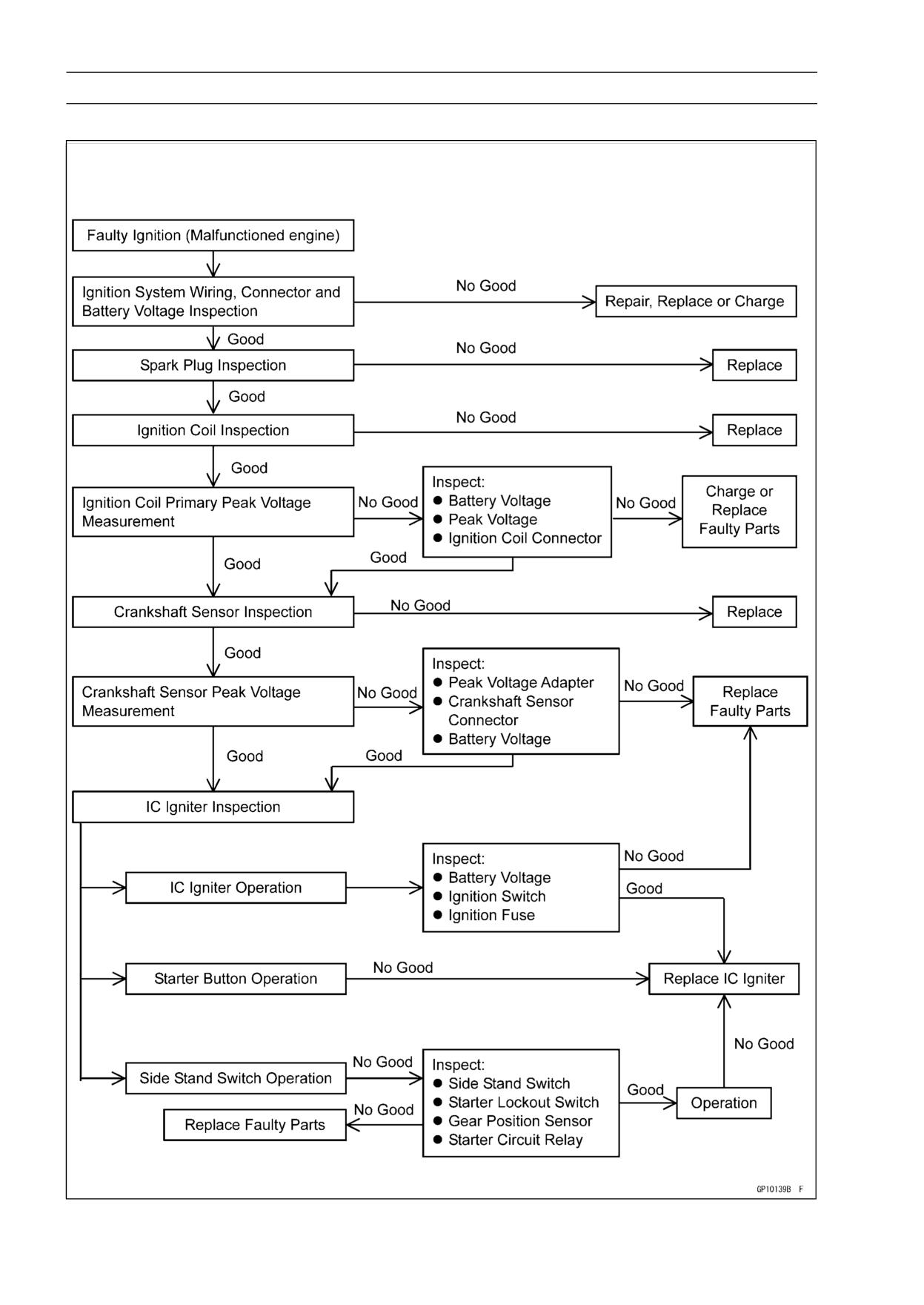
Charging System Circuit
1. Ignition Switch
2. Alternator
3. Regulator/Rectifier
4. Battery
5. Main Fuse 30 A
6. Load
16-38 ELECTRICAL SYSTEM
Ignition System
Ignition System Troubleshooting
ELECTRICAL SYSTEM 16-39
Ignition System
WARNING
The ignition system produces extremely high volt-
age. Do not touch the spark plug, ignition coil or ig-
nition coil lead while the engine is running, or you
could receive a severe electrical shock.
NOTICE
Do not disconnect the battery cables or any other
electrical connections when the ignition switch is
on, or while the engine is running. This is to prevent
IC igniter damage.
Do not install the battery backwards. The negative
side is grounded. This is to prevent damage to the
diodes and IC igniter.
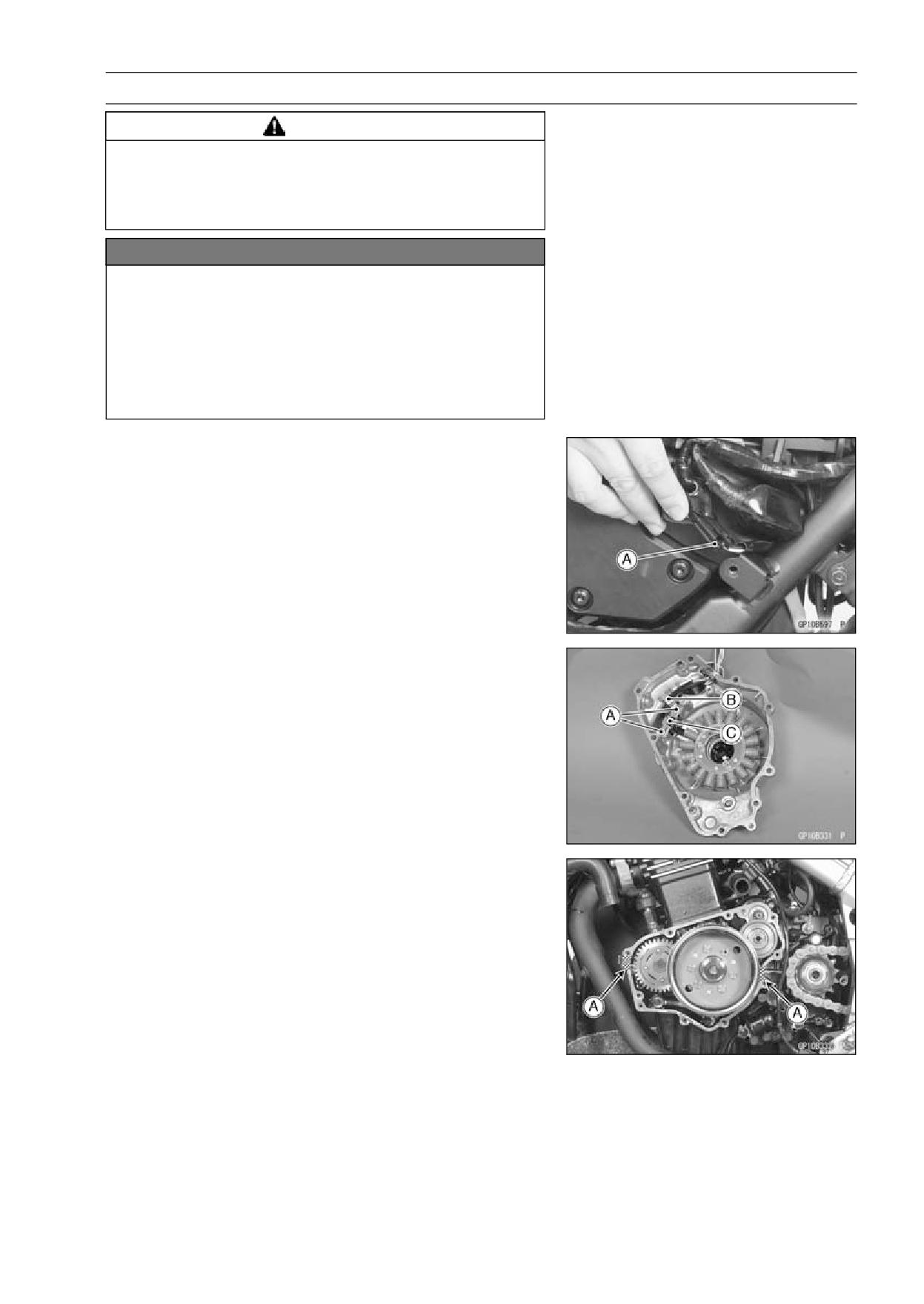
Crankshaft Sensor Removal
• Remove:
Front Seat (see Front Seat Removal in the Frame chap-
ter)
Left Lower Fairing (see Lower Fairing Removal in the
Frame chapter)
Alternator Cover (see Alternator Cover Removal)
• Disconnect the crankshaft sensor connector [A].
• Remove the crankshaft sensor screws [A] and clamp [B],
and then remove the crankshaft sensor [C].
Crankshaft Sensor Installation
• Apply silicone sealant to the grommet and fit it into the
notch in the alternator cover.
• Install the clamp and crankshaft sensor to the alternator
cover.
• Clamp the harness of crankshaft sensor leads as shown.
• Apply liquid gasket to the mating surface [A] of the
crankcase.
• Install the alternator cover (see Alternator Cover Installa-
tion).
Sealant - Liquid Gasket, TB1211: 56019-120
16-40 ELECTRICAL SYSTEM
Ignition System
Crankshaft Sensor Inspection
• Remove the right side cover (see Side Cover Removal in
the Frame chapter).
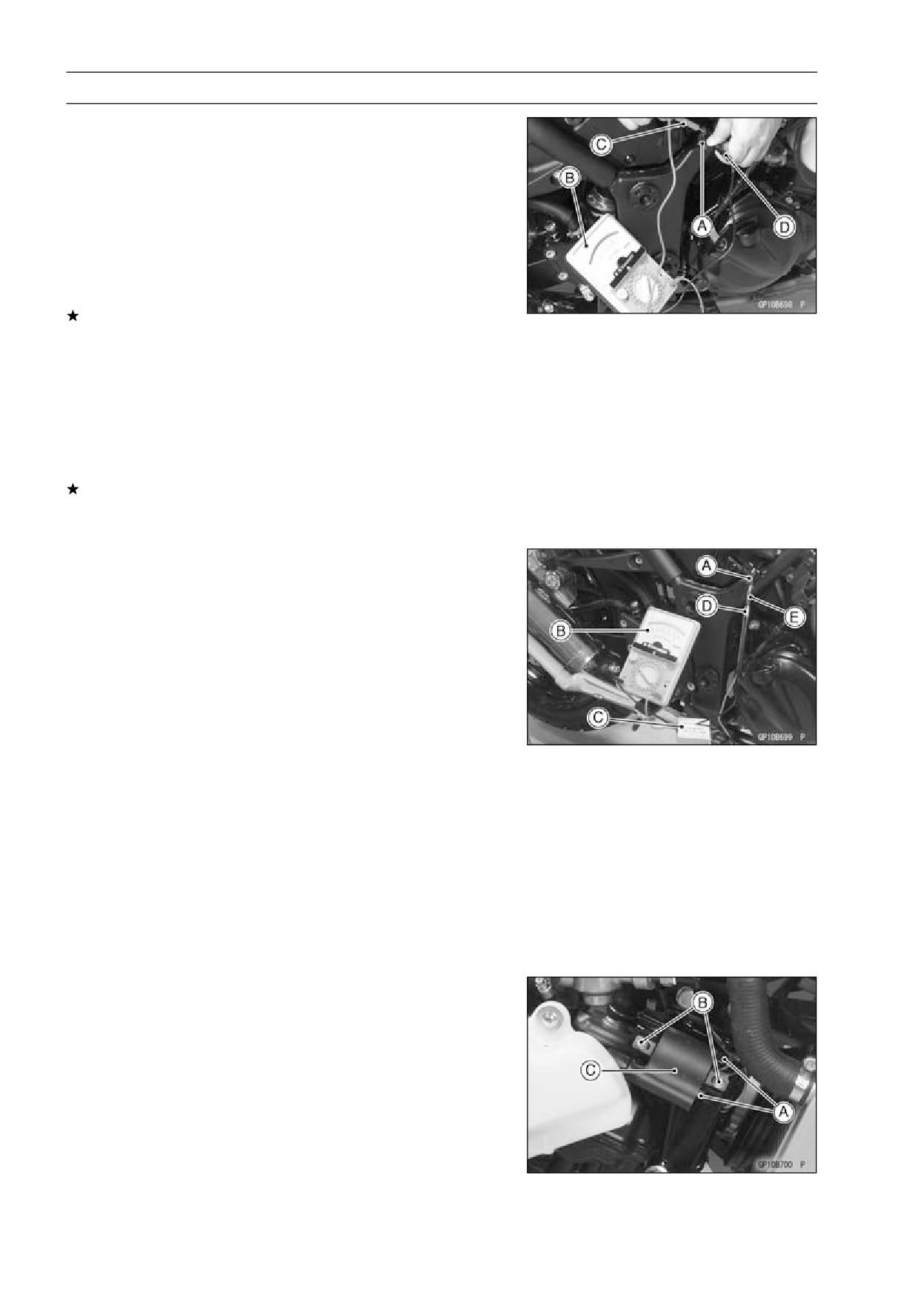
• Disconnect the crankshaft sensor connector [A] from near
the right side of the carburetor.
• Set the hand tester [B] to the × 100 Ω range and connect
the (+) lead [C] to the black lead and (-) lead [D] to the
yellow lead in the connector.
Special Tool - Hand Tester: 57001-1394
If there is more resistance than the specified value, the
coil has an open lead and must be replaced. Much less
than this resistance means the coil is shorted, and must
be replaced.
Crankshaft Sensor Resistance: 100 ∼ 150 Ω
• Using the highest resistance range of the tester, measure
the resistance between the crankshaft sensor leads and
chassis ground.
Any tester reading less than infinity (∞) indicates a short,
necessitating replacement of the crankshaft sensor as-
sembly.
Crankshaft Sensor Peak Voltage Inspection
• Disconnect the crankshaft sensor connector [A].
• Set the hand tester [B] to the × 25 V DC range, and con-
nect it the peak voltage adapter [C] as shown in the dia-
gram.
• Using two auxiliary wires, connect the black lead (-) of the
adapter to black lead [D] and red lead (+) to yellow lead
[E] in the crankshaft sensor connector [A].
• Turn the ignition switch and engine stop switch on.
• Grasp the clutch lever and pushing the starter button, turn
the engine 4 ∼ 5 seconds with the transmission gear in
neutral to measure the crankshaft sensor peak voltage.
• Repeat the measurement 5 or more times.
Crankshaft Sensor Peak Voltage
Standard:
3.2 V or more
Special Tool - Hand Tester: 57001-1394
Peak Voltage Adapter: 57001-1415
Type: KEK-54-9-B
Ignition Coil Removal
• Remove:
Front Seat (see Front Seat Removal in the Frame chap-
ter)
Fuel Tank (see Fuel Tank Removal in the Fuel System
chapter)
Right or Left Lower Fairing (see Lower Fairing Removal
in the Frame chapter)
• Disconnect the primary winding leads [A] from the ignition
coil.
• Pull out the spark plug cap from the spark plug.
• Remove the mounting bolts [B], and take out the ignition
coil [C].
ELECTRICAL SYSTEM 16-41
Ignition System
Ignition Coil Installation
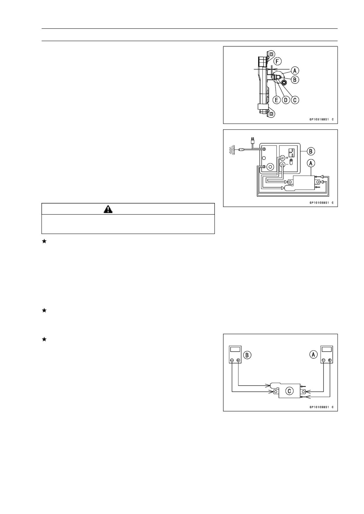
• Install the ignition coil as shown (both sides).
Ignition Coil (Right Side) [A]
Bolt [B]
Washer [C]
Nut [D]
Washer [E]
0 ∼ 3 mm (0.12 in.) [F]
Ignition Coil Inspection
• Remove the ignition coil (see ignition Coil Removal).
• Measure the arcing distance with the suitable commer-
cially available coil tester [B] to check the condition of the
ignition coil [A].
• Connect the ignition coil (with the spark plug cap left at-
tached at the end of the spark plug lead) to the tester in
the manner prescribed by the manufacturer and measure
the arcing distance.
WARNING
To avoid extremely high voltage shocks, do not
touch the coil body or leads.
If the distance reading is less than the specified value, the
ignition coil or spark plug cap is defective.
Ignition Coil Arcing Distance
Standard: 7 mm (0.28 in.) or more
• To determine which part is defective, measure the arcing
distance again with the spark plug cap removed from the
ignition coil. Remove the cap by turning it counterclock-
wise.
If the arcing distance is subnormal as before, the trouble
is with the ignition coil itself. If the arcing distance is now
normal, the trouble is with the spark plug cap.
If the coil tester is not available, the coil [C] can be
checked for a broken or badly shorted winding with the
hand tester (special tool).
Special Tool - Hand Tester: 57001-1394
NOTE
○The hand tester cannot detect layer shorts and shorts
resulting from insulation breakdown under high voltage.
• Measure the primary winding resistance [A] as follows.
○Connect the hand tester between the coil terminal and
primary winding terminal.
16-42 ELECTRICAL SYSTEM
Ignition System
• Measure the secondary winding resistance [B] as follows.
○Remove the plug cap by turning it counterclockwise.
○Connect the tester between the high tension lead and the
ignition coil terminal.
If the tester does not read as specified, replace the coil.
Ignition Coil Resistance
Standard: Primary windings 2.1 ∼ 3.2 Ω (× 1 Ω)
Secondary windings 10 ∼ 16 kΩ (× 1 kΩ)
Special Tool - Hand Tester: 57001-1394
• Visually inspect the secondary winding lead.
If it is damaged, replace the ignition coil.
Ignition Coil Primary Peak Voltage
NOTE
○Be sure the battery is fully charged.
• Remove:
Front Seat (see Front Seat Removal in the Frame chap-
ter)
Fuel Tank (see Fuel Tank Removal in the Fuel System
chapter)
Right or Left Lower Fairing (see Lower Fairing in the
Frame chapter)
• Remove the spark plug cap.
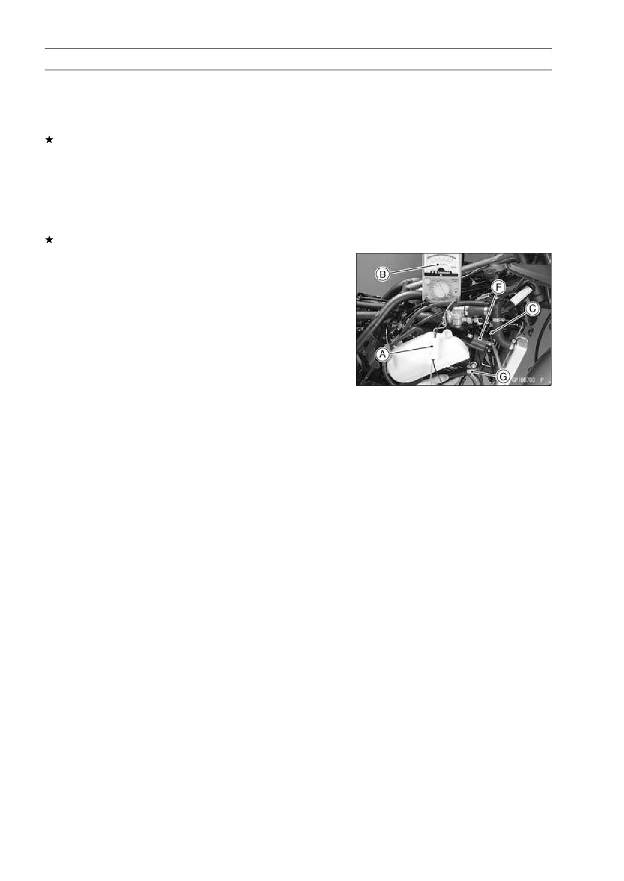
• Measure the ignition coil primary peak voltage as follows.
• Install the new spark plug [G] into the spark plug cap, and
ground it onto the engine.
• Connect the peak voltage adapter [A] into the hand tester
[B] and set it to the × 250 V DC range.
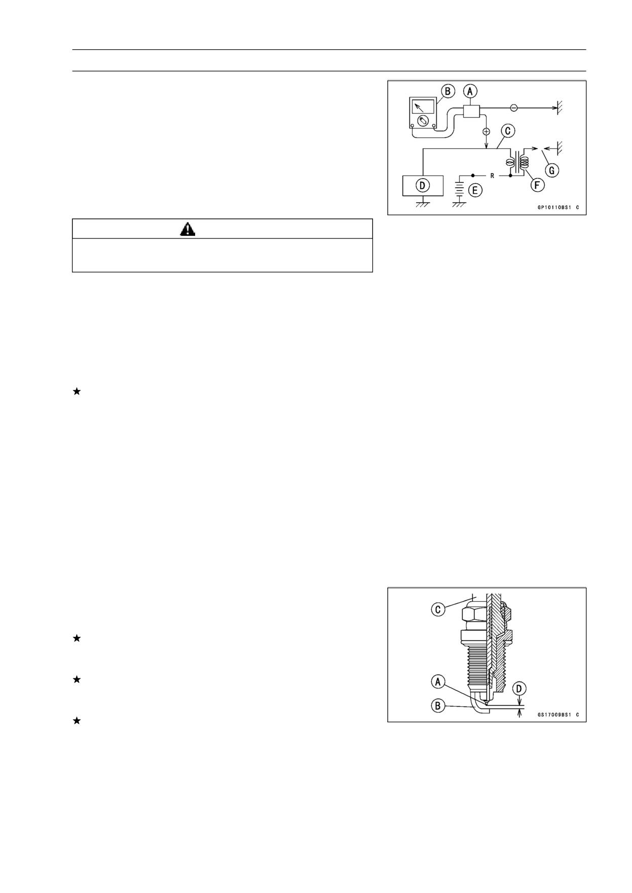
ELECTRICAL SYSTEM 16-43
Ignition System
Adapter red lead →
Ignition Coil Primary Lead
Terminal [C]
Adapter black lead →
Ignition Coil Ground Terminal
IC Igniter [D]
Battery [E]
Ignition Coil [F]
Special Tool - Hand Tester: 57001-1394
Peak Voltage Adapter: 57001-1415
Type: KEK-54-9-B
WARNING
To avoid extremely high voltage shock, do not
touch the spark plug or tester connection.
• Turn the ignition switch and engine stop switch on.
• Pushing the starter button, turn the engine 4 ∼ 5 seconds
with the transmission in neutral to measure the ignition
coil primary peak voltage.
• Repeat the measurement 5 or more times.
Ignition Coil Primary Peak Voltage
Standard:
223 V or more
If the reading is less than the specified value, check the
following:
Ignition Coil (see Ignition Coil Inspection)
Crankshaft Sensor (see Crankshaft Sensor Inspection)
IC Igniter (see IC Igniter Inspection)
Spark Plug Removal
• Refer to Spark Plug Replacement in the Periodic Mainte-
nance chapter (see Spark Plug Replacement in the Peri-
odic Maintenance chapter).
Spark Plug Installation
• Refer to Spark Plug Replacement in the Periodic Mainte-
nance chapter (see Spark Plug Replacement in the Peri-
odic Maintenance chapter).
Spark Plug Condition Inspection
• Remove the spark plugs (see Spark Plug Replacement).
• Visually inspect the spark plugs.
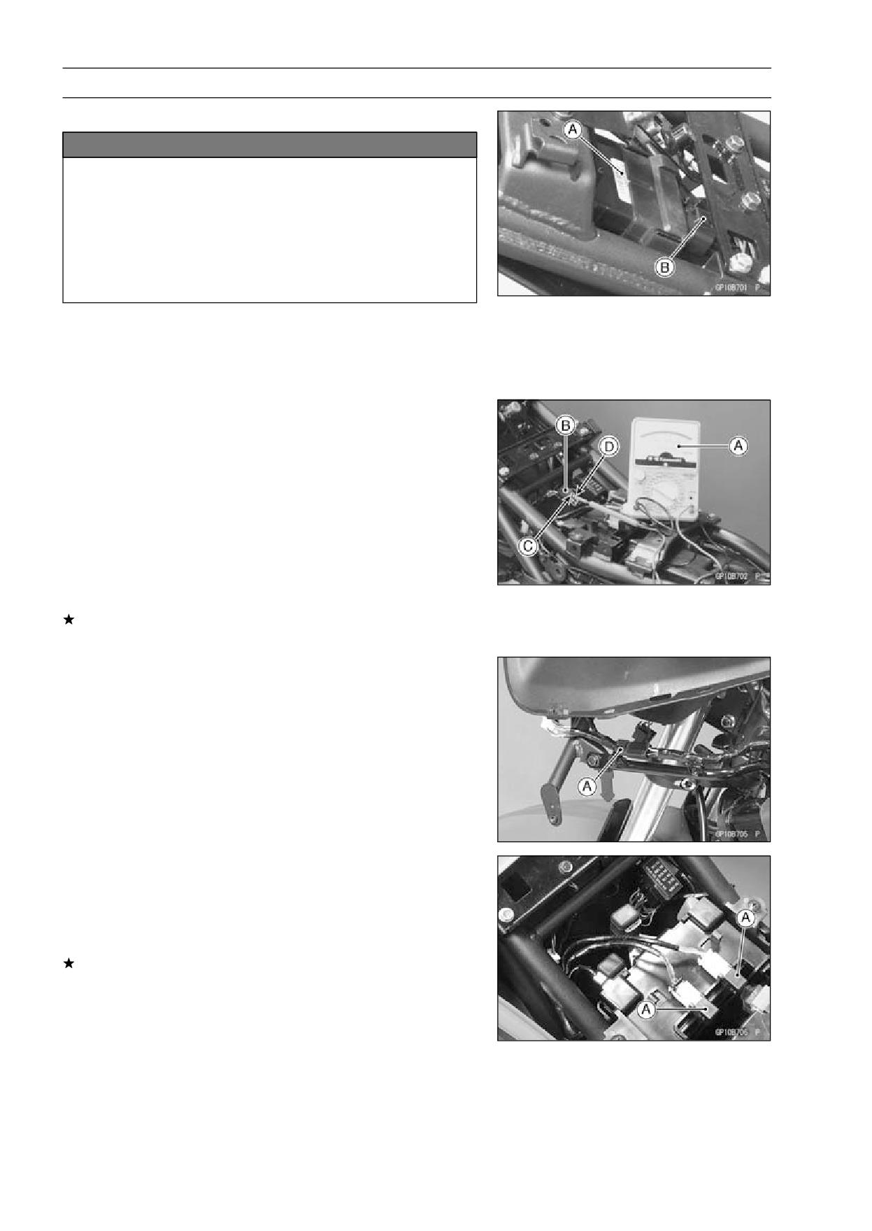
If the spark plug center electrode [A] and/or side elec-
trode [B] are corroded or damaged, or if the insulator [C]
is cracked, replace the plug.
If the spark plug is dirtied or the carbon is accumulated,
replace the spark plug.
• Measure the gap [D] with a wire-type thickness gauge.
If the gap is incorrect, replace the spark plug.
Spark Plug Gap:
0.7 ∼ 0.8 mm (0.03 ∼ 0.04 in.)
• Use the standard spark plug or its equivalent.
Spark Plug:
CR8E or U24ESR-N
16-44 ELECTRICAL SYSTEM
Ignition System
IC Igniter Inspection
NOTICE
When inspecting the IC igniter [A], observe the fol-
lowing to avoid damage to the IC igniter.
Do not disconnect the IC igniter connector [B] with
the ignition switch on.
This may damage the IC igniter.
Do not disconnect the battery leads while the en-
gine is running. This may damage the IC igniter.
IC Igniter Operation Inspection
• Remove the seat cover (see Rear Fender Removal in the
Frame chapter).
• Disconnect the IC Igniter connector.
• Set the hand tester [A] to the × 25 V DC range, and con-
nect it to the connector [B] come from harness side as
follows.
Tester (+) terminal [C] → BR/BK lead
Tester (-) terminal [D] → BK/Y lead
Special Tool - Hand Tester: 57001-1394
Needle Adapter Set: 57001-1457
• Turn the ignition switch on, and read the voltage.
IC Igniter Operation Voltage: Battery Voltage
If the tester reading is not specified one, check the battery
voltage, ignition switch and ignition fuse.
Diodes Inspection
• Remove the left lower fairing (see Lower Fairing in the
Frame chapter).
• Disconnect the diode [A].
• Remove the front seat (see Front Seat Removal in the
Frame chapter).
• Disconnect the diode assemblies [A].
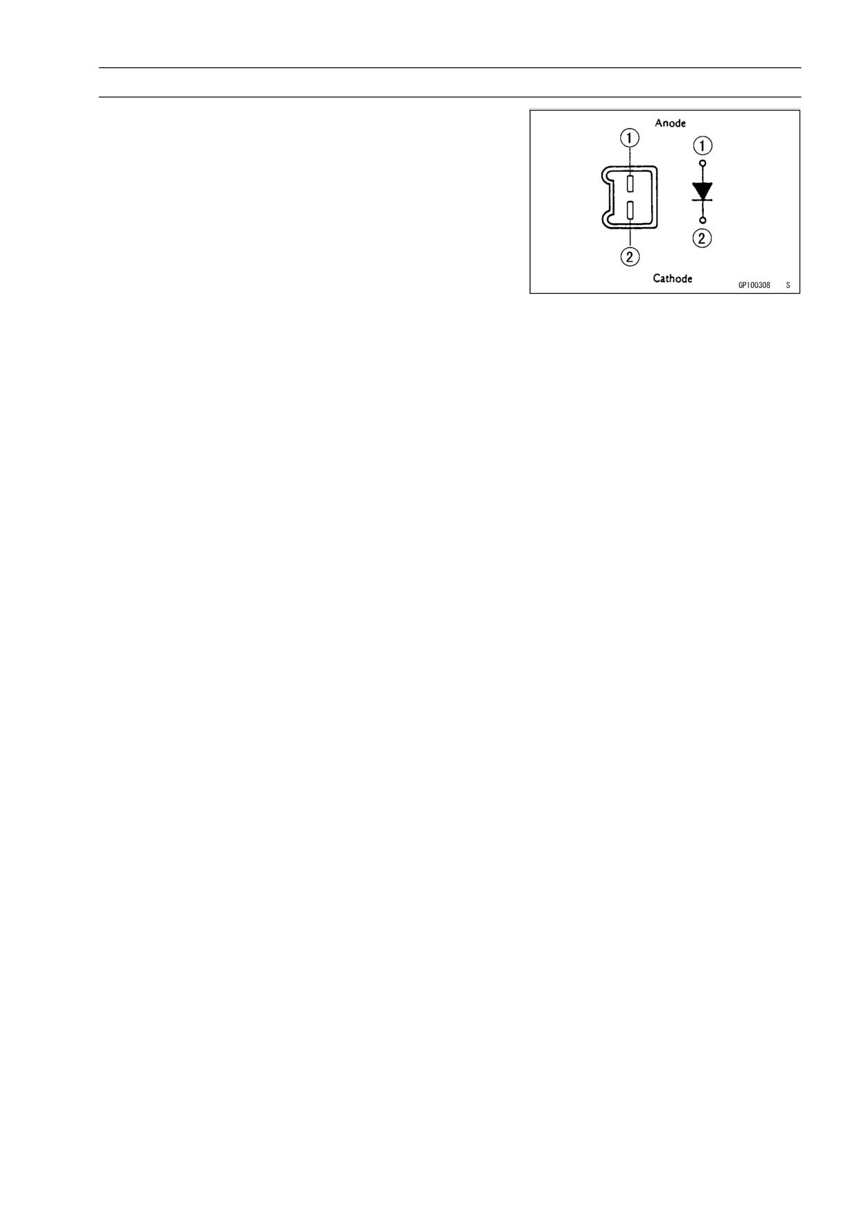
• Zero the hand tester, and connect it to each diode terminal
to check the resistance in both directions.
The resistance should be low in one direction and more
than ten times as much in the other direction. If any diode
shows low or high in both directions, the diode is defective
and the diode assembly must be replaced.
ELECTRICAL SYSTEM 16-45
Ignition System
NOTE
○The actual meter reading varies with the meter used
and the individual diode, but, generally speaking, the
lower reading should be from zero to one half the scale.
16-46 ELECTRICAL SYSTEM
Ignition System
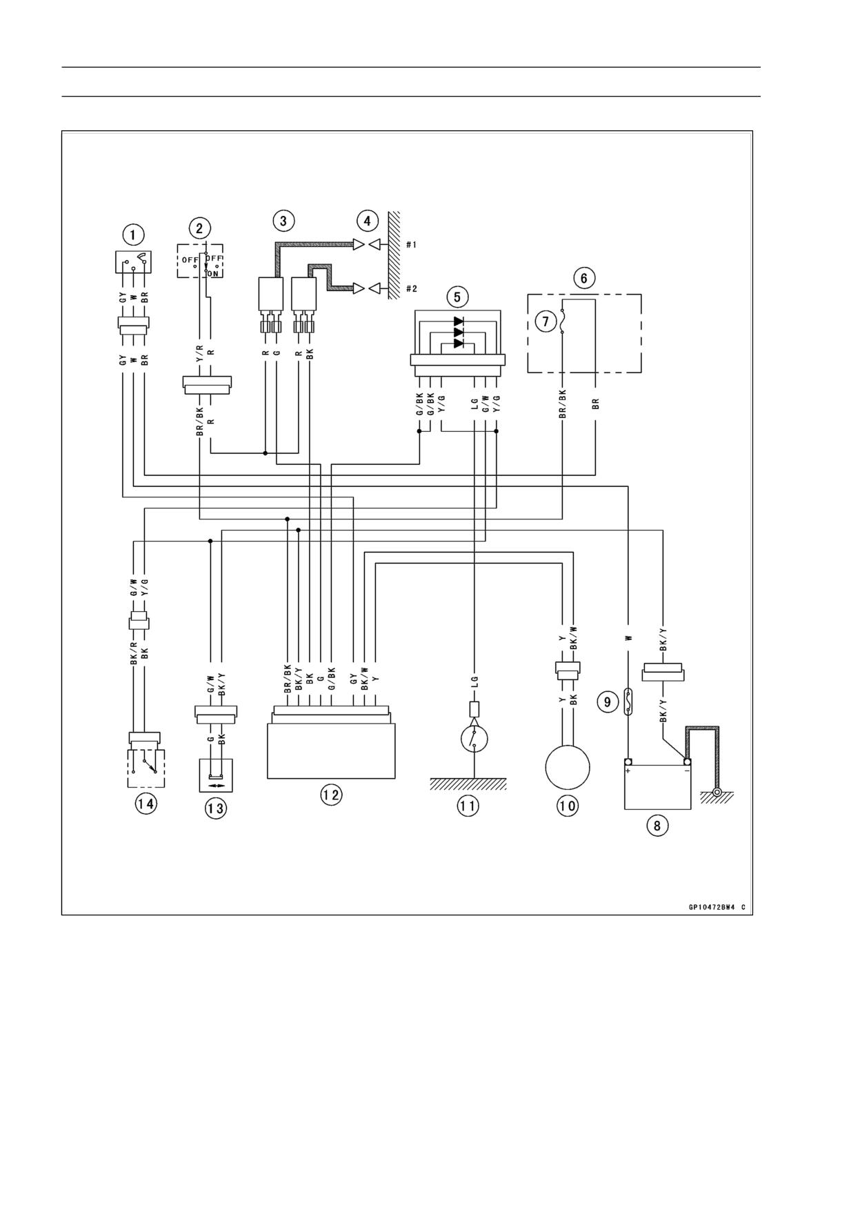
Ignition System Circuit
1. Ignition Switch
2. Engine Stop Switch
3. Ignition Coils
4. Spark Plugs
5. Diode A
6. Fuse Box
7. Ignition Fuse 10 A
8. Battery
9. Main Fuse 30 A
10. Pickup Coil
11. Neutral Switch
12. IC Igniter
13. Sidestand Switch
14. Starter Lockout Switch
ELECTRICAL SYSTEM 16-47
Electric Starter System
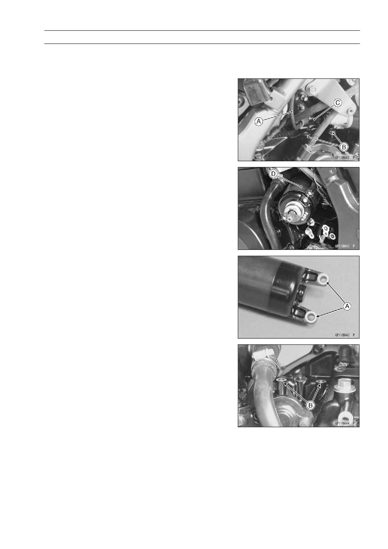
Starter Motor Removal
• Remove the lower fairings (see Lower Fairing Removal in
the Frame chapter).
• Disconnect the starter motor lead [A] from the starter mo-
tor [C].
• Remove the starter mounting bolts [B] and pull out [D] the
starter motor toward the left side.
Starter Motor Installation
• Clean the starter motor lugs [A] and crank case surface
[B] where the starter motor is grounded.
16-48 ELECTRICAL SYSTEM
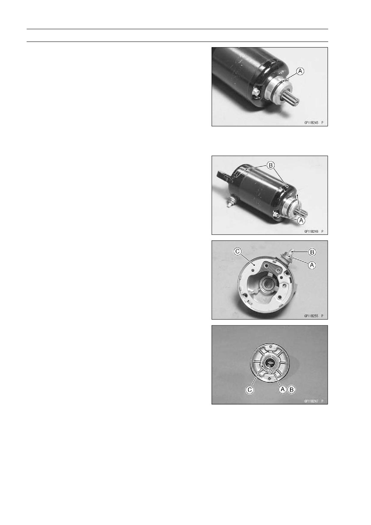
Electric Starter System
• Apply a small amount of engine oil to the O-ring [A].
• Put the starter motor on the crankcase.
• Press the part of the starter motor end cover and push the
starter motor into the crankcase hole.
• Tighten the starter motor mounting bolts.
• Connect the starter motor lead to the starter motor termi-
nal.
• Install:
Starter Idle Gear
Alternator Cover
Engine Sprocket Cover
Shift Lever
Water Pipes
Starter Motor Disassembly
• Remove the starter motor (see Starter Motor Removal).
• Remove the bolts [A] and take out both end covers [B].
• Take the armature off from the pinion gear side of the
yoke.
• Remove the terminal locknut [A] and washers, and then
remove the brush and terminal bolt [B] with the brush plate
[C] from the yoke.
Starter Motor Assembly
• Replace the O-rings with a new ones.
• Apply a thin coat of high-temperature grease to the oil seal
[A] and needle bearing [B].
• Fit the toothed washer [C] into the end cover.
ELECTRICAL SYSTEM 16-49
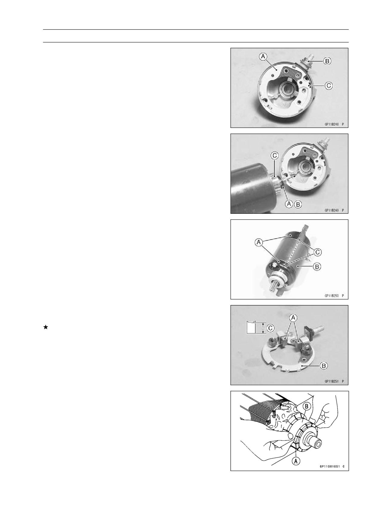
Electric Starter System
• Install the brush, terminal bolt, washers with the brush
plate [A] and tighten the terminal locknut [B].
Torque - Starter Motor Terminal Locknut:
9.8
N·m (1.0
kgf·m, 87 in·lb)
• Fit the tongue [C] on the brush plate into the end cover
groove.
• Install the steel washer [A] and resin washer [B] into the
starter shaft, and insert the armature [C] between the
brushes.
• Align the end cover [A] with the mark [C] of the yoke [B].
Torque - Starter Motor Assembly Bolts:
3.5
N·m (0.36
kgf·m, 31 in·lb)
Carbon Brush Inspection
• Measure the length [C] of each brush [A].
If any is worn down to the service limit, replace the carbon
brush holder assembly [B].
Carbon Brush Length
Standard:
10 mm (0.39 in.)
Service Limit: 5 mm (0.20 in.)
Commutator Inspection, Cleaning
• Smooth the commutator surface [A] if necessary with fine
emery cloth [B], and clean out the grooves.
16-50 ELECTRICAL SYSTEM
Electric Starter System
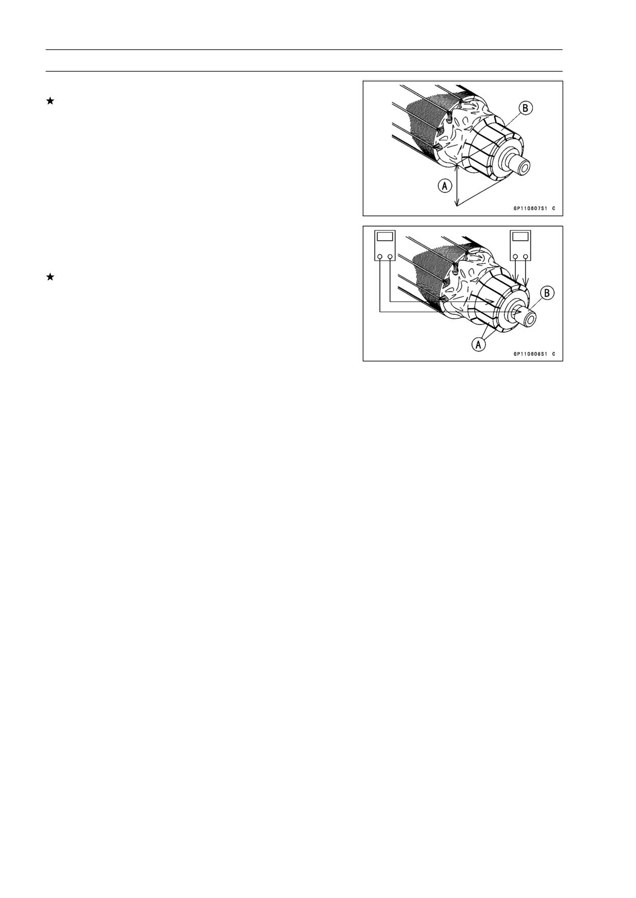
• Measure the outer diameter [A] of the commutator [B].
Replace the starter motor with a new one if the commu-
tator diameter is less than the service limit.
Commutator Diameter
Standard:
28 mm (1.10 in.)
Service Limit:
27 mm (1.06 in.)
Armature Inspection
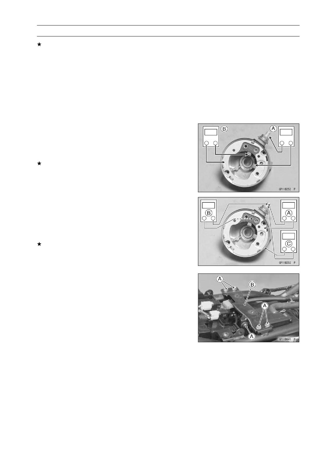
• Using the × 1 Ω hand tester range, measure the resis-
tance between any two commutator segments [A].
If there is a high resistance or no reading (∞) between any
two segments, a winding is open and the starter motor
must be replaced.
• Using the highest hand tester range, measure the resis-
tance between the segments and the shaft [B].
ELECTRICAL SYSTEM 16-51
Starter System
If there is any reading at all, the armature has a short and
the starter motor must be replaced.
Special Tool - Hand Tester: 57001-1394
NOTE
○Even if the foregoing checks show the armature to be
good, it may be defective in some manner not readily
detectable with the hand tester. If all other starter motor
and starter motor circuit components check good, but
the starter motor still does not turn over or only turns
over weakly, replace the starter motor with a new one.
Brush Lead Inspection
• Using the × 1 Ω hand tester range, measure the continuity
between the following:
Terminal Bolt and Positive (+) Brush [A]
Brush Plate and Negative (-) Brush [B]
If there is not close to zero ohms, the brush lead has
an open. Replace the terminal bolt assembly and/or the
brush holder assembly.
Special Tool - Hand Tester: 57001-1394
Terminal Bolt Inspection
• Using the highest hand tester range, measure the resis-
tance as shown.
Terminal Bolt and Brush Plate [A]
Terminal Bolt and Negative Brush Holder [B]
Terminal Bolt and Yoke [C]
If there is any reading, the brush holder assembly and/or
terminal bolt assembly have a short. Replace the brush
holder assembly and the terminal bolt assembly.
Special Tool - Hand Tester: 57001-1394
Starter Relay Inspection
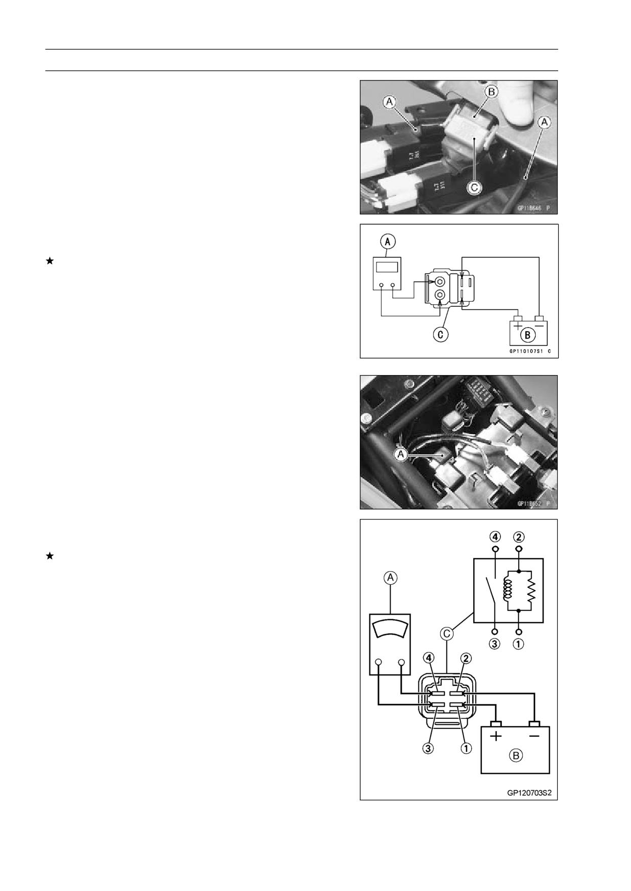
• Remove the fuel tank (see Fuel Tank Removal in the Fuel
System chapter).
• Remove:
Fuel Tank Bracket Bolts [A]
Fuel Tank Bracket [B]
16-52 ELECTRICAL SYSTEM
Starter System
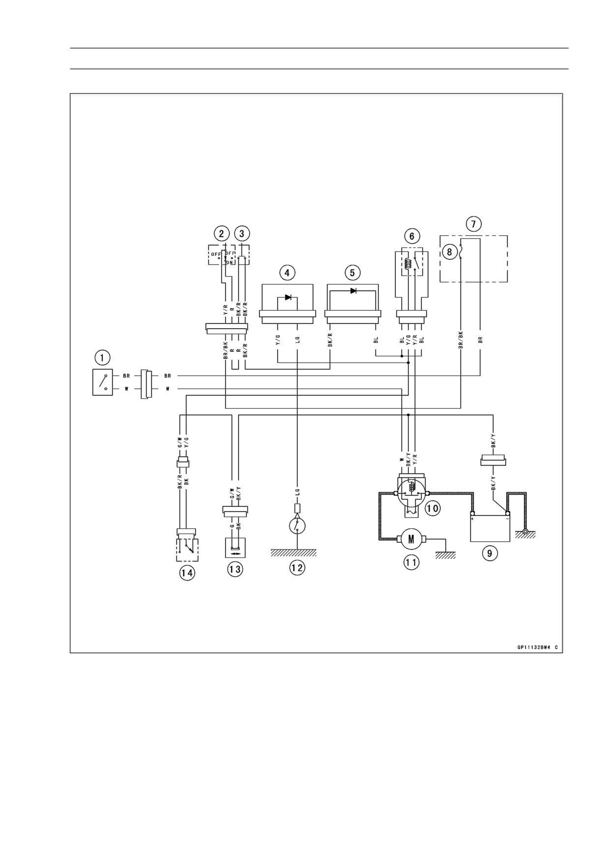
• Disconnect the cables [A] and remove the starter relay [C]
with the main fuse [B].
• Remove the main fuse from the starter relay.
• Connect the hand tester [A] and 12 V battery [B] to the
starter relay [C] as shown.
If the relay does not work as specified, the relay is defec-
tive. Replace the relay.
Relay Function Test
Tester Range: × 1 Ω range
Standard: When battery is connected → 0 Ω
When battery is disconnected → ∞ Ω
Special Tool - Hand Tester: 57001-1394
Starter Circuit Relay Inspection
• Remove the front seat (see Front Seat Removal in the
Frame chapter).
• Remove the starter circuit relay [A].
• Connect the hand tester [A] and 12 V battery [B] to the
starter circuit relay [C] as shown.
If the relay does not work as specified, the relay is defec-
tive. Replace the relay.
Testing Relay
Tester Range:
× 1 Ω
Criteria:
When battery is connected → 0 Ω
When battery is disconnected → ∞ Ω
Relay Coil Terminal [1] and [2]
Relay Switch Terminals [3] and [4]
ELECTRICAL SYSTEM 16-53
Starter System
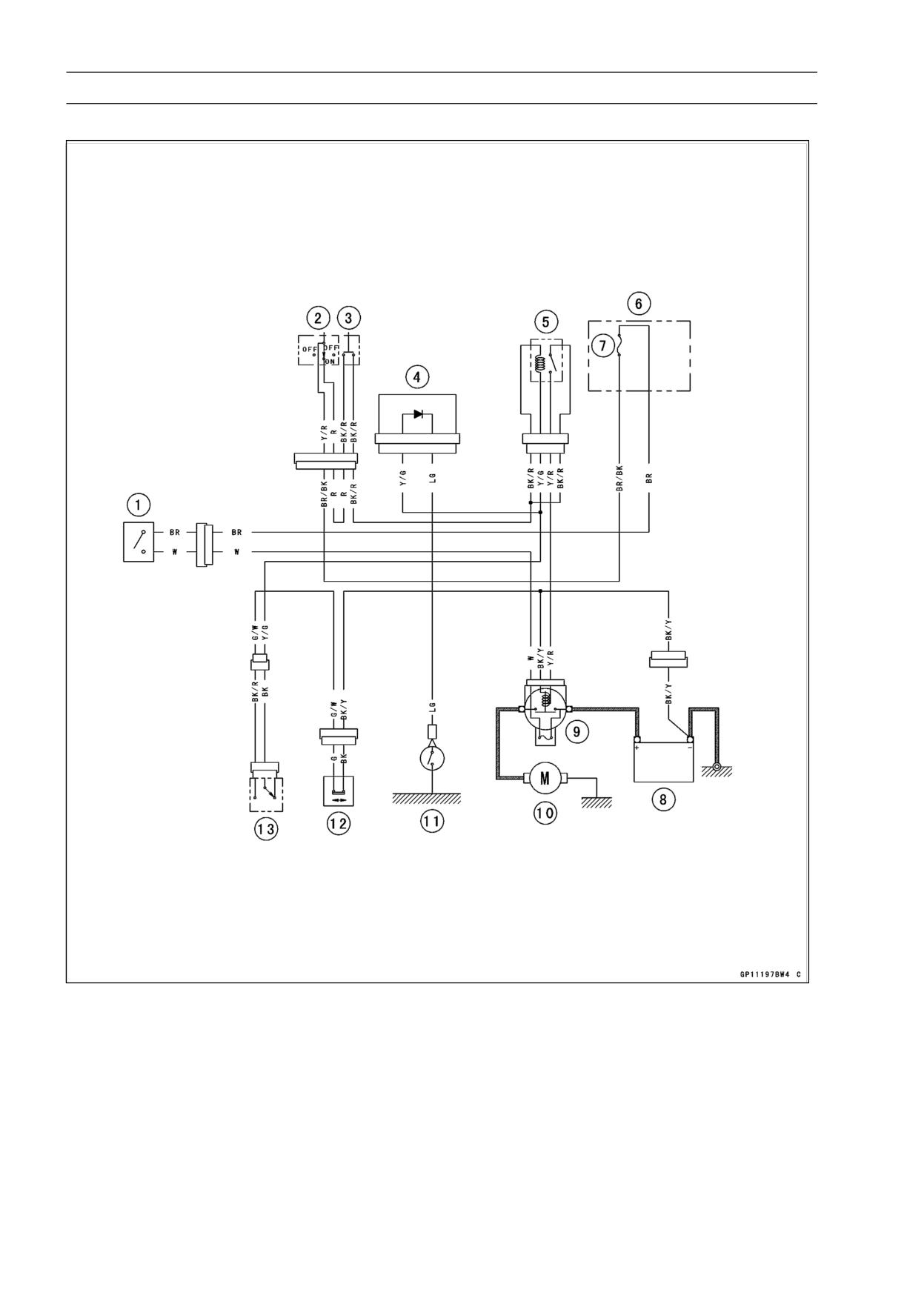
Electrical Starter Circuit (EX250J8/J9)
1. Ignition Switch
2. Engine Stop Switch
3. Starter Button
4. Diode A
5. Diode B
6. Starter Circuit Relay
7. Fuse Box
8. Ignition Fuse 10 A
9. Battery
10. Main Fuse 30 A
11. Starter Motor
12. Neutral Switch
13. Sidestand Switch
14. Starter Lockout Switch
16-54 ELECTRICAL SYSTEM
Starter System
Electrical Starter Circuit (EX250JA ∼ JC)
1. Ignition Switch
2. Engine Stop Switch
3. Starter Button
4. Diode A
5. Starter Circuit Relay
6. Fuse Box
7. Ignition Fuse 10 A
8. Battery
9. Main Fuse 30 A
10. Starter Motor
11. Neutral Switch
12. Sidestand Switch
13. Starter Lockout Switch
ELECTRICAL SYSTEM 16-55
Lighting System
Headlight Beam Horizontal Adjustment
• Refer to Headlight Aiming Inspection in the Periodic Main-
tenance chapter (see Headlight Aiming Inspection in the
Periodic Maintenance chapter).
Headlight Beam Vertical Adjustment
• Refer to Headlight Aiming Inspection in the Periodic Main-
tenance chapter (see Headlight Aiming Inspection in the
Periodic Maintenance chapter).
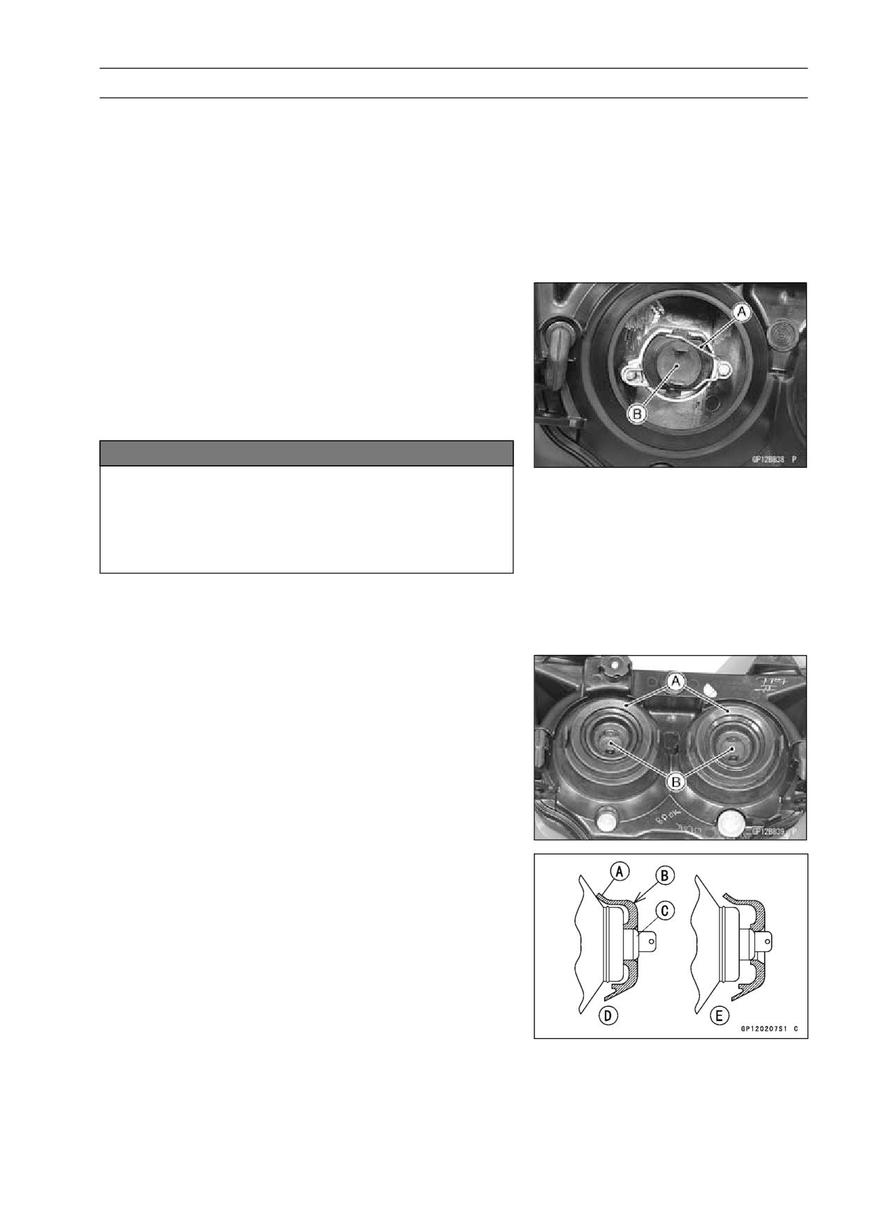
Headlight Bulb Replacement
• Remove:
Upper Fairing (see Upper Fairing Removal in the Frame
chapter)
Headlight Connector
Headlight Bulb Dust Cover
Clip [A] (Disconnect)
Headlight Bulb [B]
NOTICE
When handling the quartz-halogen bulb, never
touch the glass portion with bare hands. Always
use a clean cloth. Oil contamination from hands or
dirty rags can reduce bulb life or cause the bulb to
explode.
NOTE
○Clean off any contamination that inadvertently gets on
the bulb with alcohol or soap and water solution.
• Fit the dust cover [A] firmly onto the bulb [B] as shown.
Dust Cover [A]
Top Mark [B]
Bulb [C]
Good [D]
Bad [E]
• Connect the headlight connector.
• Adjust the headlight beam (see Headlight Aiming Inspec-
tion in the Periodic Maintenance chapter).
16-56 ELECTRICAL SYSTEM
Lighting System
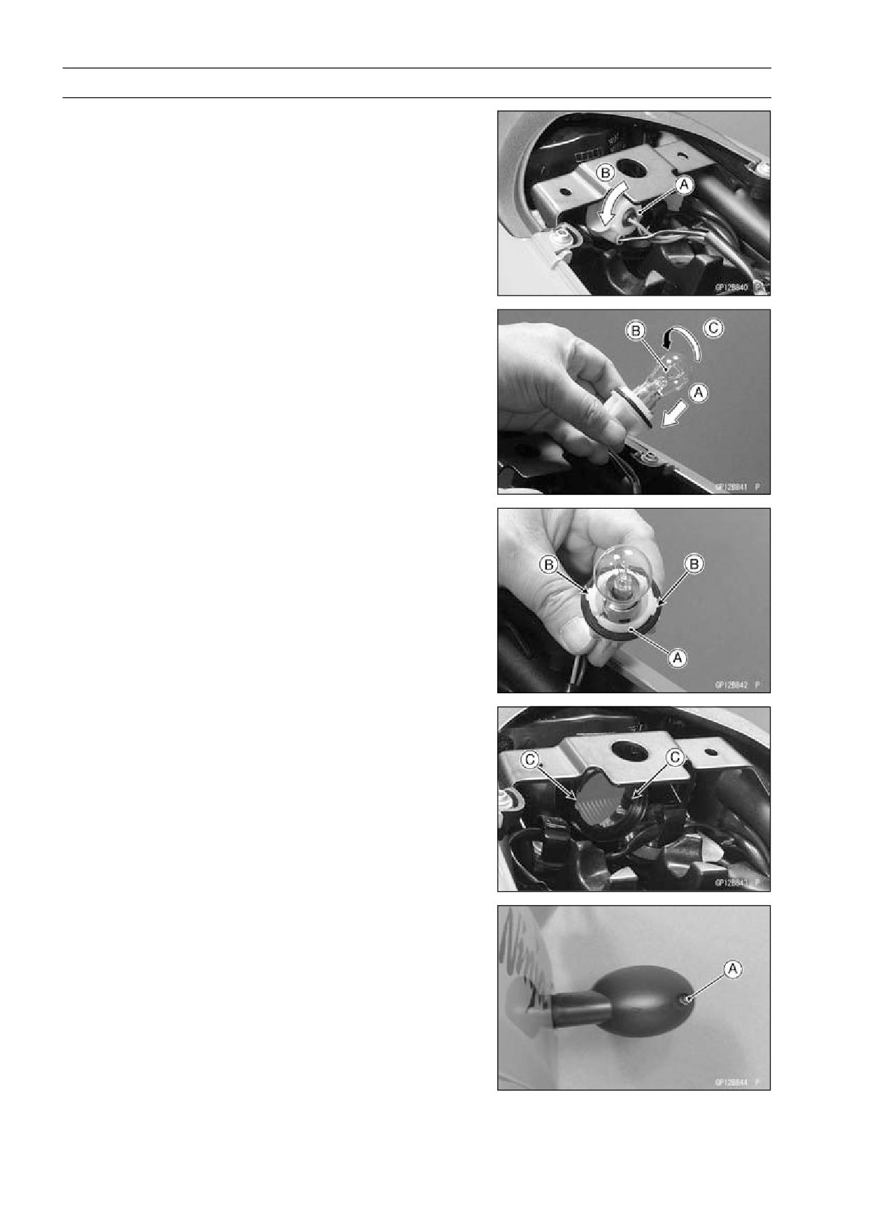
Tail/Brake Light Bulb Replacement
• Remove the rear seat (see Rear Seat Removal in the
Frame chapter).
• Unscrew the socket [A] counterclockwise [B].
• Push [A] the bulb [B] in the socket, turn it counterclock-
wise [C], and pull it out.
• Push the bulb in and turn it clockwise.
• Screw in the socket [A] aligning the tabs [B] with the re-
cesses [C].
Front Turn Signal Light Bulb Replacement
• Remove the lens mounting screw [A] and remove lens.
ELECTRICAL SYSTEM 16-57
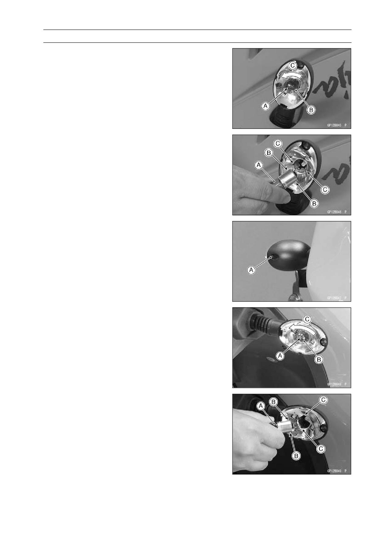
Lighting System
• Push [A] the bulb [B] in and turn [C] it counterclockwise
and then remove it.
• Insert the new bulb [A] by aligning the projections [B] with
the grooves [C] in the socket.
• Push the bulb and turn it clockwise and then replace it. It
should lock in lock position.
• Insert the socket by aligning the projection with the notch
in the wall and turn the socket clockwise.
Rear Turn Signal Light Bulb Replacement
• Remove the lens mounting screw [A] and remove the
lens.
• Push [A] the bulb [B] in and turn [C] it counterclockwise,
and then remove it.
• Insert the new bulb [A] by aligning the projections [B] with
the grooves [C] in the wall of the socket.
• Push the bulb in and turn it clockwise and then install it.
It should lock in position.
• Install the lens, and tighten the lens mounting screw. Be
careful not to overtighten the lens mounting screw.
16-58 ELECTRICAL SYSTEM
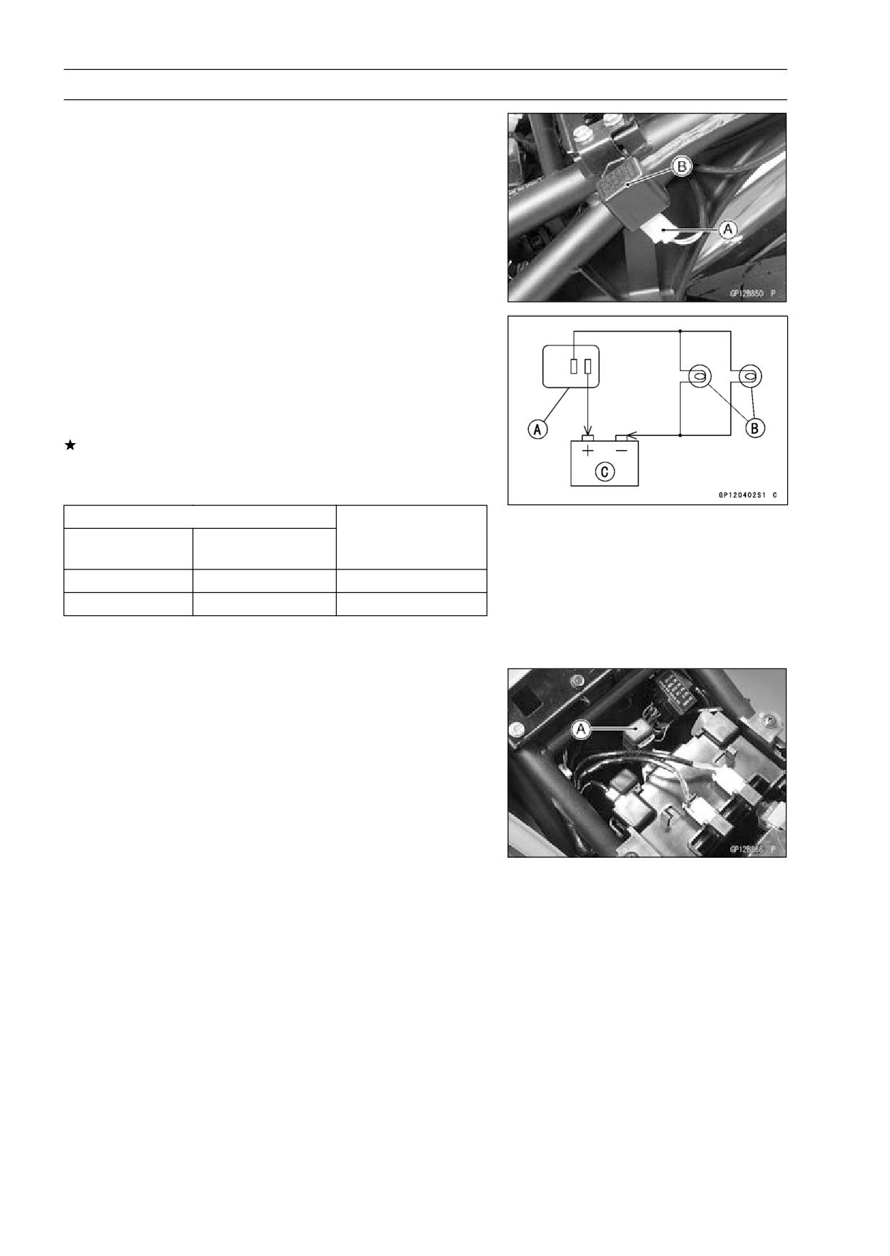
Lighting System
Turn Signal Relay Inspection
• Remove:
Seat Cover (see Rear Fender Removal in the Frame
chapter)
Turn Signal Relay Connector [A]
Turn Signal Relay [B]
• Connect one 12 V battery and turn signal lights as indi-
cated in the figure, and count how many times the lights
flash for one minute.
Turn Signal Relay [A]
Turn Signal Lights [B]
12 V Battery [C]
If the lights do not flash as specified, replace the turn sig-
nal relay.
Testing Turn Signal Relay
Load
The Number of
Flashing times (c/m*)
Wattage (W)
Turn Signal Lights
1**
21 or 23
Light stays on
2
42 or 46
75-95
(*): Cycle(s) per minute
(**): Correspond to “one light burned out”
Headlight Circuit Relay Inspection
• Remove the front seat (see Front Seat Removal in the
Frame chapter).
• Remove the headlight circuit relay [A].
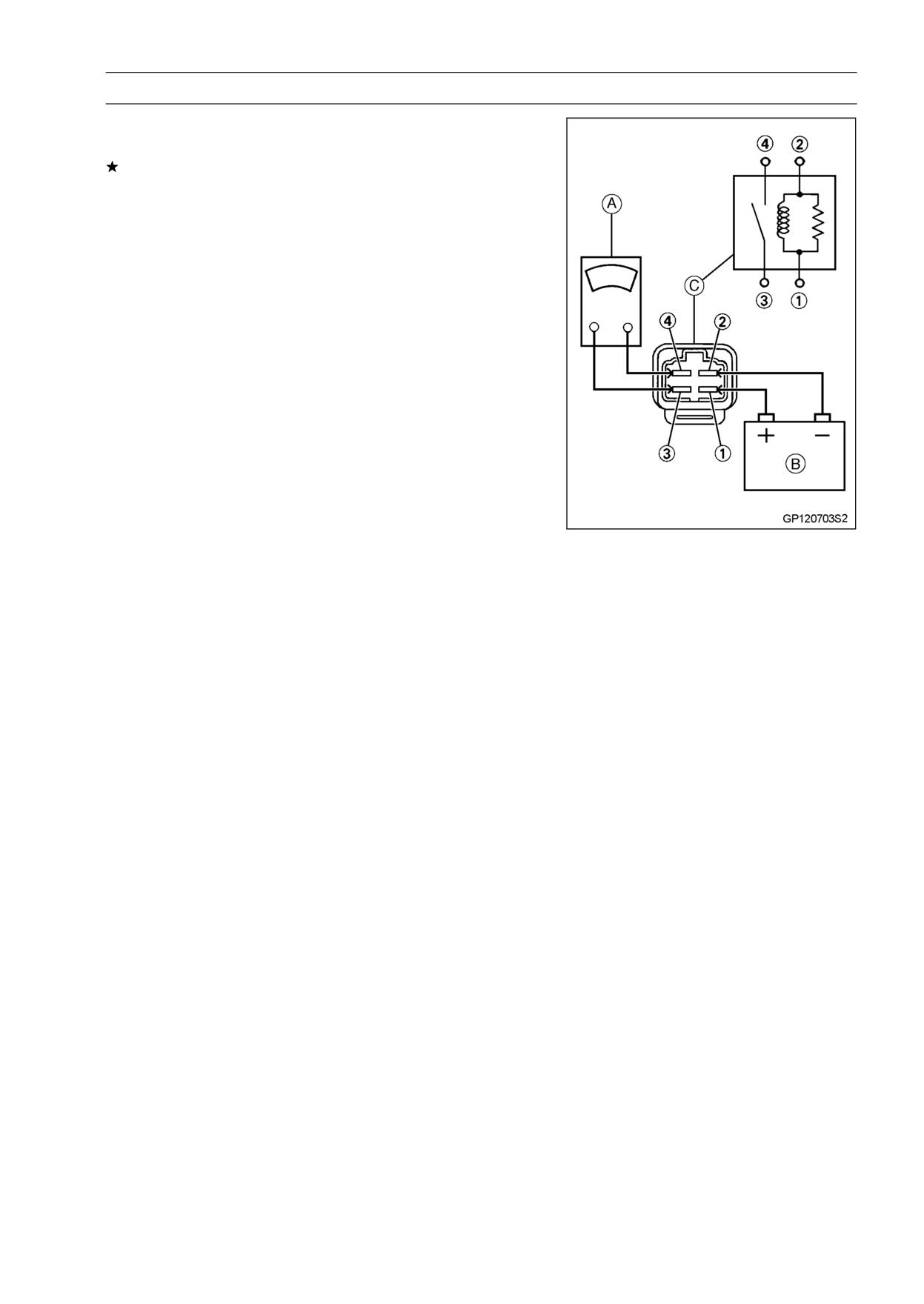
ELECTRICAL SYSTEM 16-59
Lighting System
• Connect the hand tester [A] and 12 V battery [B] to the
starter circuit relay [C] as shown.
If the relay does not work as specified, the relay is defec-
tive. Replace the relay.
Testing Relay
Tester Range:
× 1 Ω
Criteria:
When battery is connected → 0 Ω
When battery is disconnected → ∞ Ω
Relay Coil Terminal [1] and [2]
Relay Switch Terminals [3] and [4]
16-60 ELECTRICAL SYSTEM
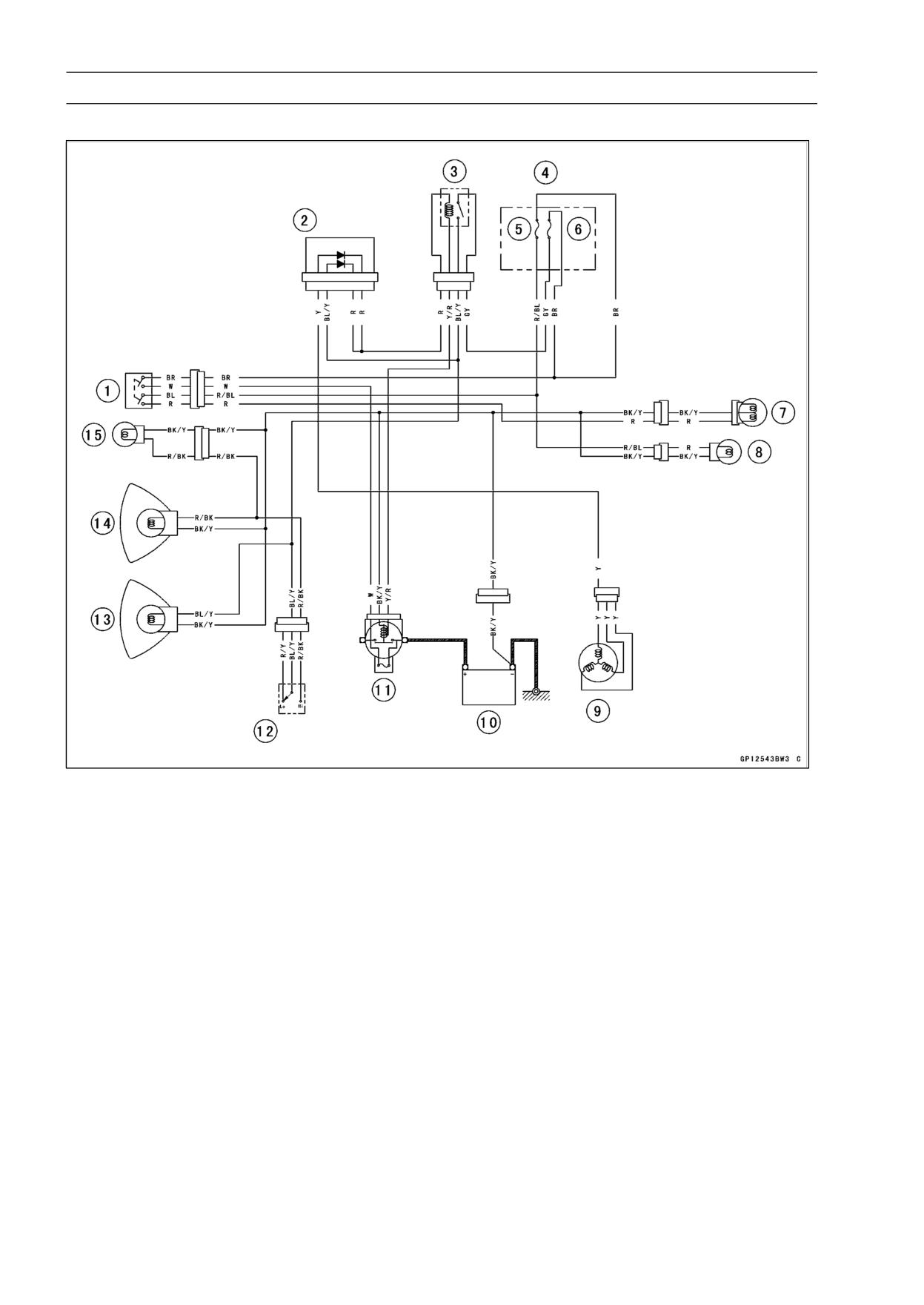
Lighting System
Headlight/Tail Light Circuit (other than Indonesia and Philippines)
1. Ignition Switch
2. Diode B
3. Headlight Relay
4. Fuse Box
5. Tail Light Fuse 10 A
6. Headlight Fuse 10 A
7. Tail/Brake Light
8. License Plate Light
9. Alternator
10. Battery
11. Main Fuse 30 A
12. Dimmer Switch
13. Headlight (Low Beam)
14. Headlight (High Beam)
15. City Light
ELECTRICAL SYSTEM 16-61
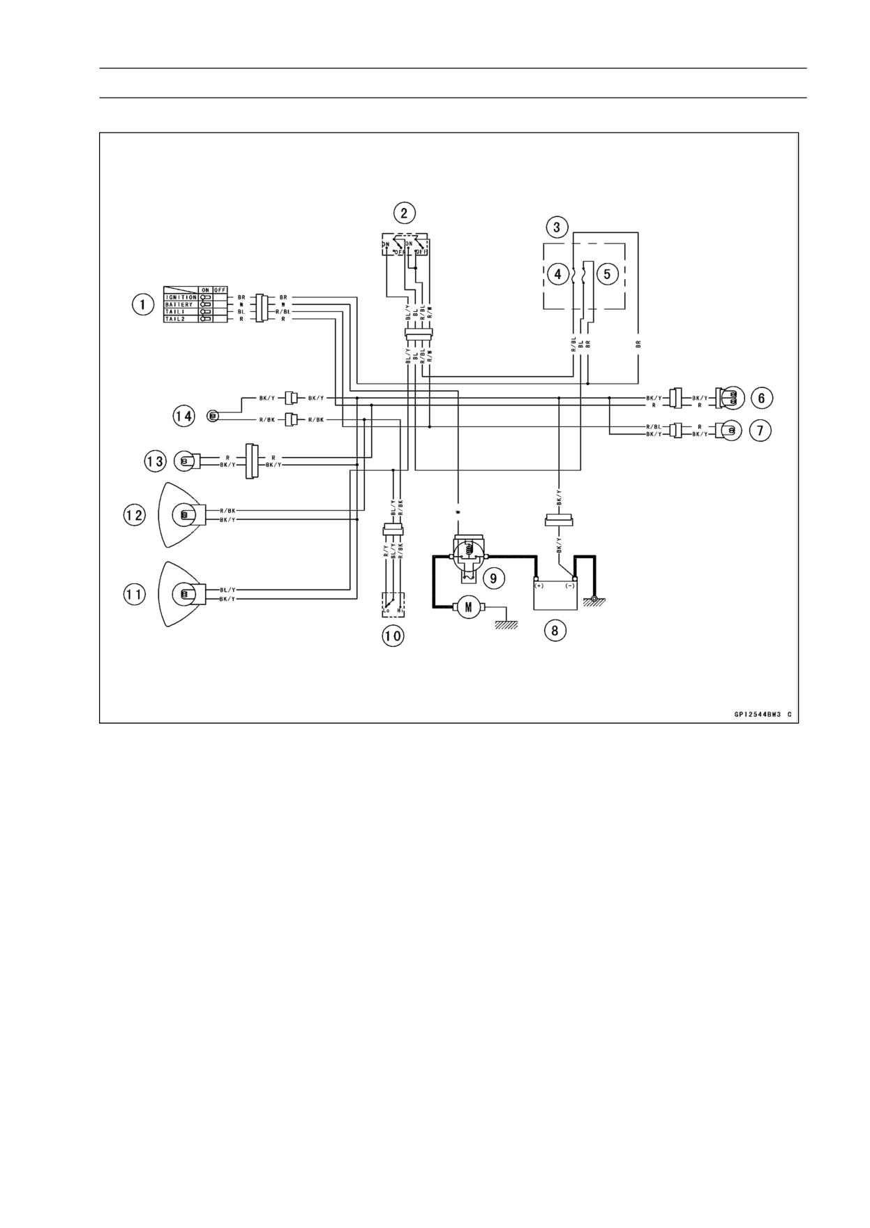
Lighting System
Headlight/Tail Light Circuit (Indonesia and Philippines)
1. Ignition Switch
2. Headlight Switch
3. Fuse Box
4. Tail Light Fuse 10 A
5. Headlight Fuse 10 A
6. Tail/Brake Light
7. License Plate Light
8. Battery
9. Main Fuse 30 A
10. Dimmer Switch
11. Headlight (Low Beam)
12. Headlight (High Beam)
13. City Light
14. High Beam Indicator Light
16-62 ELECTRICAL SYSTEM
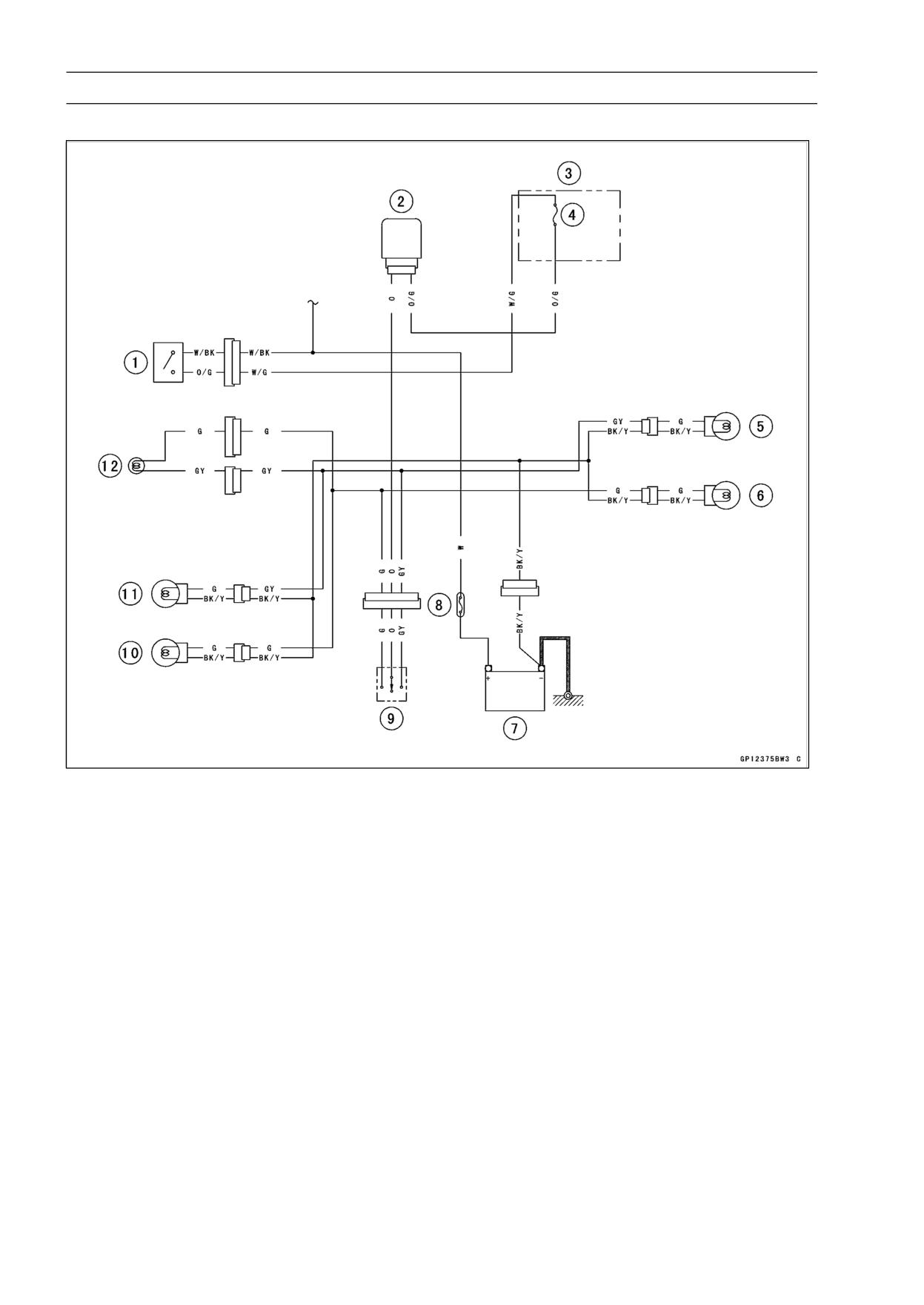
Lighting System
Turn Signal Light Circuit
1. Ignition Switch
2. Turn Signal Relay
3. Fuse Box
4. Turn Signal Relay Fuse 10 A
5. Rear Right Turn Signal Light
6. Rear Left Turn Signal Light
7. Battery
8. Main Fuse 30 A
9. Turn Signal Switch
10. Front Left Turn Signal Light
11. Front Right Turn Signal Light
12. Turn Signal Indicator Light
ELECTRICAL SYSTEM 16-63
Radiator Fan System
WARNING
A spinning radiator fan can cause serious injury.
The radiator fan is connected directly to the battery
and may start even if the ignition switch is off. Do
not touch the radiator fan until it has been discon-
nected from the battery.
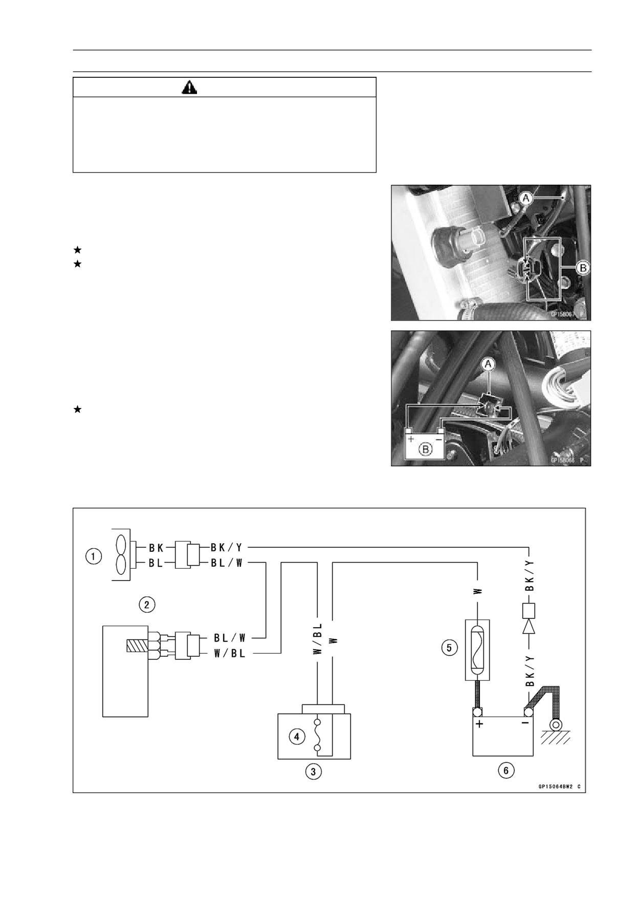
Fan System Circuit Inspection
• Disconnect the leads [A] from the radiator fan switch.
• Using an auxiliary wire [B], connect the radiator fan switch
leads.
If the fan rotates, inspect the fan switch.
If the fan does not rotate, inspect the following.
Leads and Connectors
Main Fuse and Fan Fuse
Fan Motor
Fan Motor Inspection
• Remove the right lower fairing (see Frame chapter).
• Disconnect the 2-pin connector [A] in the fan motor leads.
• Using two auxiliary wires, supply battery [B] power to the
fan motor.
If the fan does not rotate, the fan motor is defective and
must be replaced.
Lead Connections
Battery (+) → BL Lead
Battery (-) → BK Lead
Radiator Fan Circuit
1. Radiator Fan
4. Fan Fuse 10 A
2. Radiator Fan Switch
5. Main Fuse (30 A)
3. Fuse Box
6. Battery
16-64 ELECTRICAL SYSTEM
Meters, Gauge and Indicator Unit
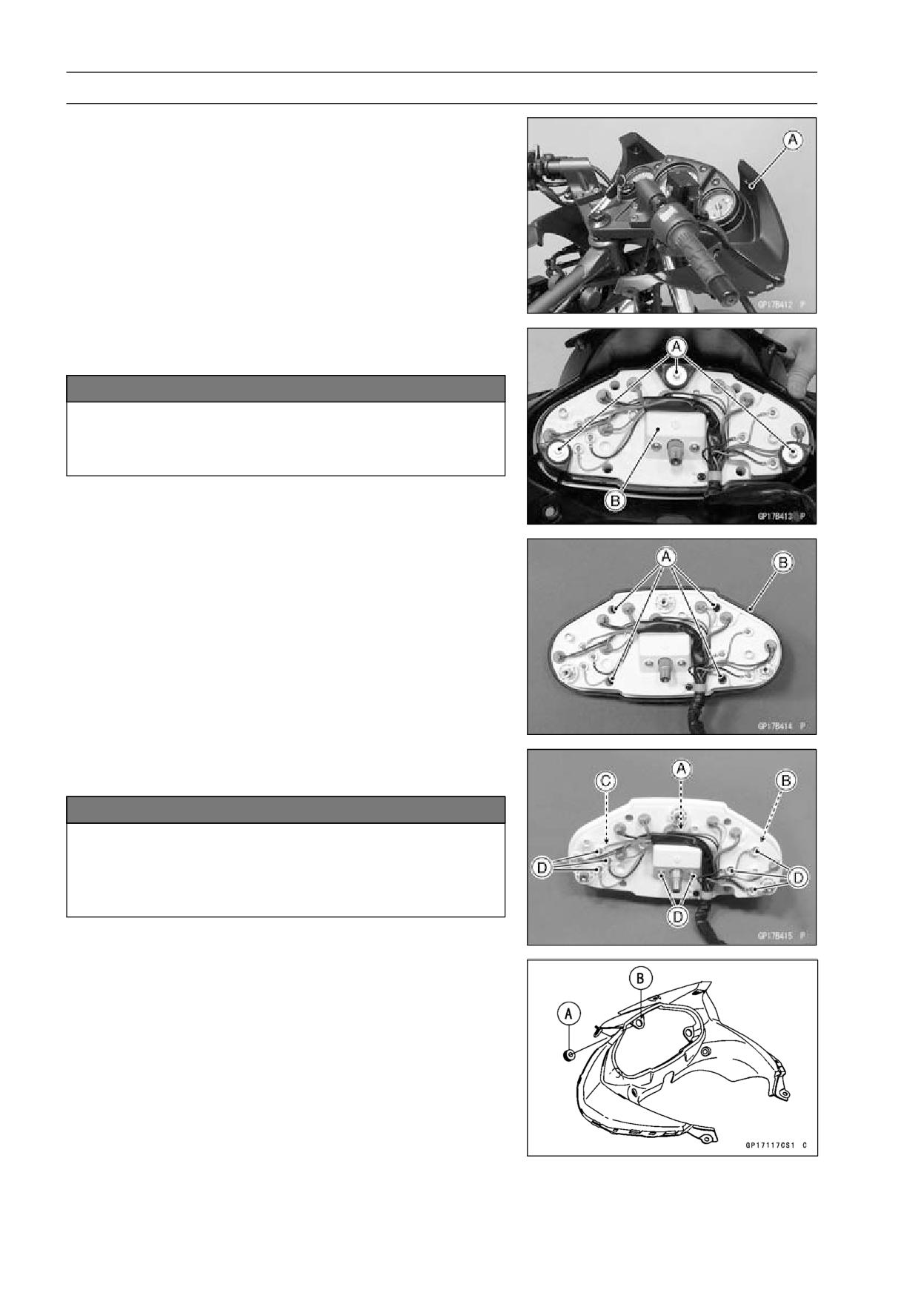
Meter Unit Removal
• Remove:
Upper Cover [A] (see Upper Cover Removal in the
Frame chapter)
• Unscrew the bolts [A] and remove the meter unit [B] from
the upper cover.
NOTICE
Place the meter unit so that the face is up. If a meter
unit is left upside down or sideways for any length
of time, it will malfunction.
Meter Unit Disassembly
• Remove:
Meter Unit (see Meter Unit Removal)
Reset Knob
Screws [A]
Meter Cover [B]
• Remove the speedometer [A], tachometer [B] and fuel
gauge [C] by removing screws [D].
NOTICE
Do not remove a meter pointer unless the meter is
to be replace. The pointers cannot be reinstalled.
The pointer mounting is different from replacement
meters.
Meter Unit Installation
• Check to see that the rubber damper [A] are installed on
the meter mounting bracket [B].
• The installation is a reverse of the meter unit removal.
ELECTRICAL SYSTEM 16-65
Meters, Gauge and Indicator Unit
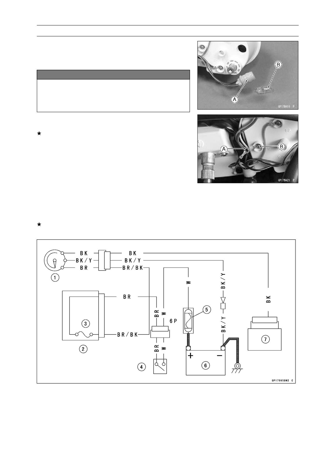
Indicator Light Replacement
• Remove the meter unit (see Meter Unit Removal).
• To remove the wedge base type bulbs, pull out the bulb
sockets [A] and pull the bulbs [B] off the sockets.
NOTICE
Do not use bulbs rated for greater wattage than
the specified wattage, as the meter or gauge panel
could become warped by excessive heat radiated
from the bulbs.
Tachometer Inspection
• Check the tachometer circuit wiring.
If all wiring and components other than the tachometer
unit check out good, the unit is suspect. Check the unit
as shown.
• Remove the following.
Upper Fairing (see Upper Fairing Removal in the Frame
chapter)
• Disconnect the BK lead.
• Reinstall the BK terminal screw.
• Turn the engine stop switch to RUN position.
• Turn the ignition switch ON.
• Open or connect the BK lead [A] to the BK terminal screw
[B]. Then the pointer should flick.
• Turn the ignition switch OFF.
If the pointer does not flick, replace the tachometer unit.
Tachometer Circuit
1. Tachometer
2. Fuse Box
3. Ignition Fuse 10 A
4. Ignition Switch
5. Main Fuse 30 A
6. Battery
7. IC Igniter
16-66 ELECTRICAL SYSTEM
Meters, Gauge and Indicator Unit
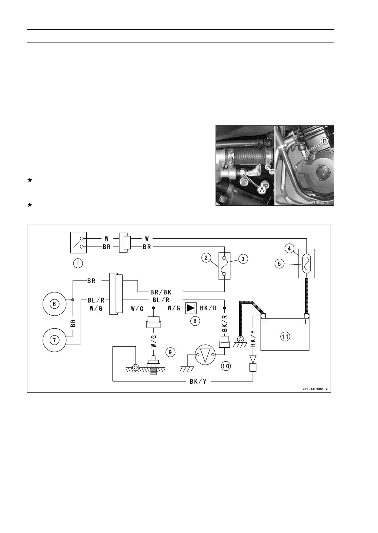
Water Temperature Warning System Inspection
The water temperature warning light goes on when the
ignition switch is turned on and goes off soon after the en-
gine starts running (oil pressure switch off) to ensure that
its circuit functions properly. The warning light also goes
on whenever the coolant temperature rises to 110 ∼ 120°C
(230 ∼ 248°F) when the motorcycles is in operation. If it
stays on, stop the engine and check the coolant level in the
reserve tank after the engine cools down.
• Inspect the water temperature warning light and the sys-
tem wiring (see Wiring Inspection).
• Turn on the ignition switch.
• Disconnect the water temperature switch lead [A] and oil
pressure switch lead, then ground them together to the
frame or engine using auxiliary lead.
If the warning light is lit, inspect the water temperature
switch (see Specifications) and the oil pressure switch [B].
Replace any switch if damaged.
If the warning light is not lit, check the warning light bulb.
Water Temperature Warning System Circuit
1. Ignition Switch
2. Fuse Box
3. Ignition Fuse 10 A
4. Starter Relay
5. Main Fuse (30 A)
6. Water Temperature Warning Light
7. Oil Pressure Waning Light
8. Diode
9. Water Temperature Switch
10. Oil Pressure Switch
11. Battery
ELECTRICAL SYSTEM 16-67
Switches and Sensor
Brake Light Timing Inspection
• Refer to Brake Light Switch Operation Inspection in the
Periodic Maintenance chapter.
Brake Light Timing Adjustment
• Refer to Brake Light Switch Operation Inspection in the
Periodic Maintenance chapter.
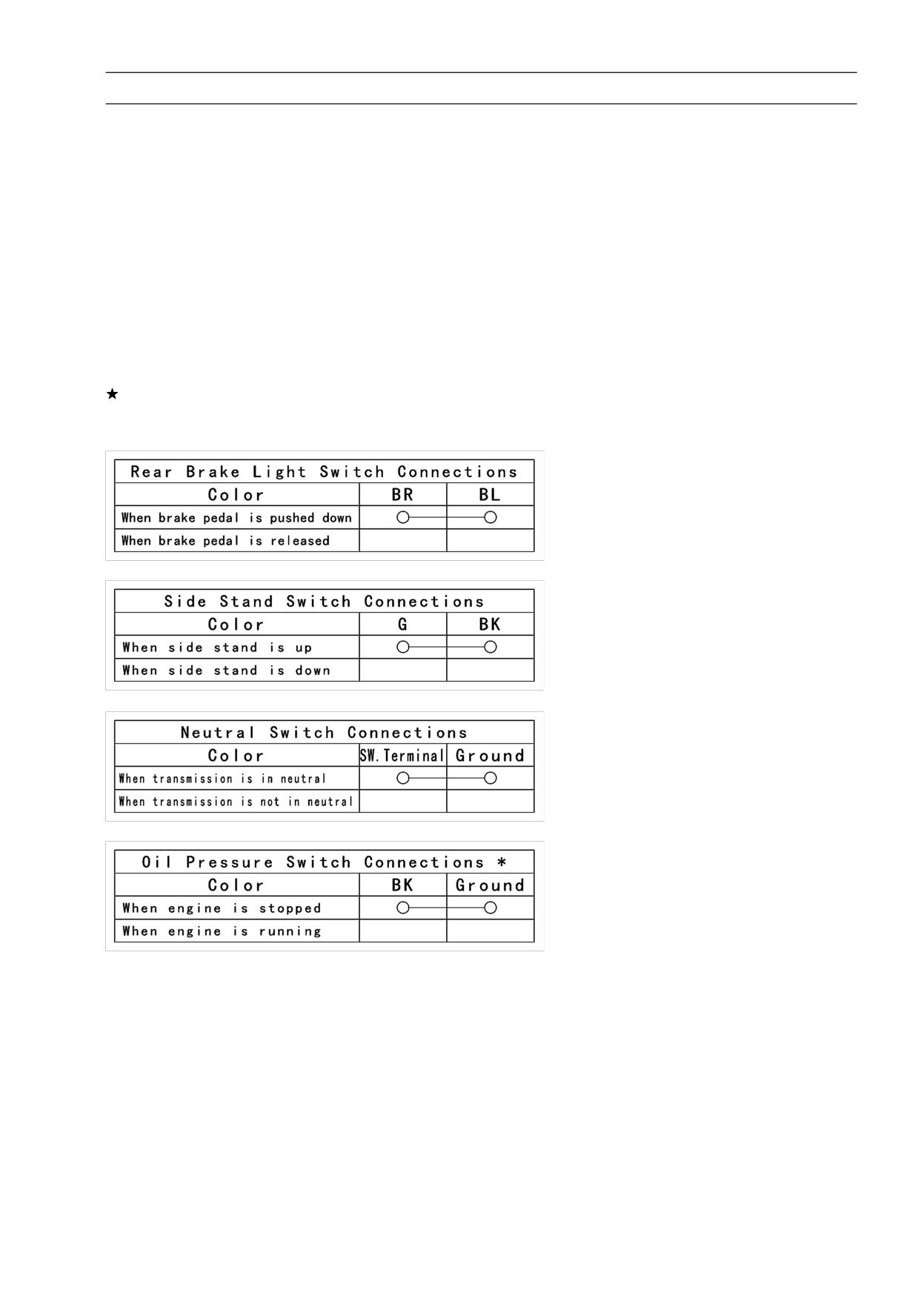
Switch Inspection
• Using a hand tester, check to see that only the con-
nections shown in the table have continuity (about zero
ohms).
○For the handlebar switches and the ignition switch, refer
to the tables in the Wiring Diagram.
If the switch has an open or short, repair it or replace it
with a new one.
Special Tool - Hand Tester: 57001-1394
*: Engine lubrication system is in good condition.
16-68 ELECTRICAL SYSTEM
Switches and Sensor
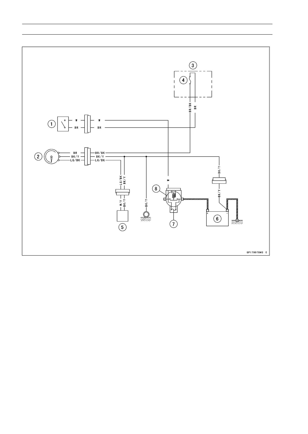
Fuel Gauge Circuit
1. Ignition Switch
2. Fuel Gauge
3. Fuse Box
4. 10 A Ignition Fuse
5. Fuel Level Sensor
6. Battery
7. 30 A Main Fuse
8. Starter Relay
ELECTRICAL SYSTEM 16-69
Switches and Sensor
Radiator Fan Switch Inspection
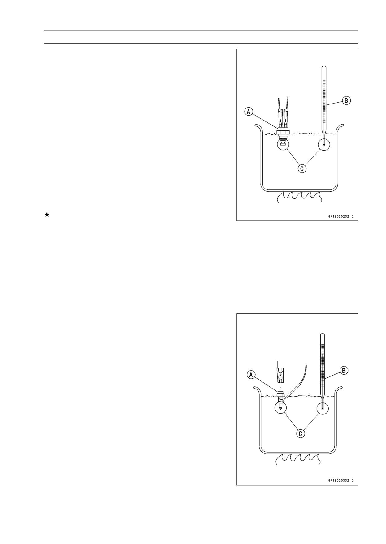
• Remove the fan switch.
• Suspend the switch [A] in a container of coolant so that
the temperature-sensing projection and threaded portion
are submerged.
• Suspend an accurate thermometer [B] in the coolant so
that the sensitive portions [C] are located in almost the
same depth.
NOTE
○The switch and thermometer must not touch the con-
tainer sides or bottom.
• Place the container over a source of heat and gradu-
ally raise the temperature of the coolant while stirring the
coolant gently.
• Using the hand tester, measure the internal resistance
of the switch across the terminals at the temperatures
shown in the table.
Special Tool - Hand Tester: 57001-1394
If the hand tester does not show the specified values, re-
place the switch.
Fan Switch Resistance
○Rising temperature:
From OFF to ON at 95 ∼ 101°C (196 ∼ 203°F)
○Falling temperature:
From ON to OFF within 3 ∼ 8°C (37 ∼ 46°F) of “ON”
temperature
ON: Less than 0.5 Ω
OFF: More than 1 MΩ
Water Temperature Switch Inspection
• Remove the water temperature switch.
• Suspend the switch [A] in a container of coolant so that
the temperature-sensing projection and threaded portion
are submerged.
• Suspend an accurate thermometer [B] in the coolant so
that the sensitive portions [C] are located in almost the
same depth.
NOTE
○The switch and thermometer must not touch the con-
tainer side or bottom.
• Place the container over a source of heat and gradu-
ally raise the temperature of the coolant while stirring the
coolant gently.
• Using the hand tester, measure the internal resistance of
the sensor across the terminal and the body at the tem-
peratures shown in the table.
Special Tool - Hand Tester: 57001-1394
16-70 ELECTRICAL SYSTEM
Switches and Sensor
If the hand tester does not show the specified values, re-
place the switch.
Water Temperature Switch Connections
Rising temperature:
From OFF to ON at 112 ∼ 118°C (226 ∼ 232°F)
Falling temperature:
From ON to OFF at 108°C (226°F) ∼ temperature less
than ON temperature
ON: Less than 0.5 Ω
OFF: More than 1 MΩ
Fuel Level Sensor Inspection
• Remove the fuel tank (see Fuel Tank Removal in the Fuel
System chapter).
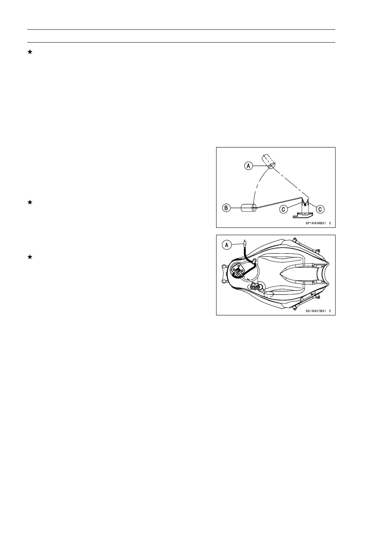
• Remove the fuel level sensor from the fuel tank.
• Check that the float moves up and down smoothly without
binding. It should go down under its own weight.
If the float does not move smoothly, replace the sensor.
[A] Float in Full Position
[B] Float in Empty Position
[C] Float Arm Stoppers
• Using a hand tester, measure the resistance across the
terminals in the fuel level sensor lead connector [A].
If the tester reading are not as specified, or do not change
smoothly according as the float moves up and down, re-
place the sensor.
Fuel Level Sensor Resistance
Standard:
Full position:
4 ∼ 10 Ω
Empty position:
90 ∼ 100 Ω
Special Tool - Hand Tester: 57001-1394
ELECTRICAL SYSTEM 16-71
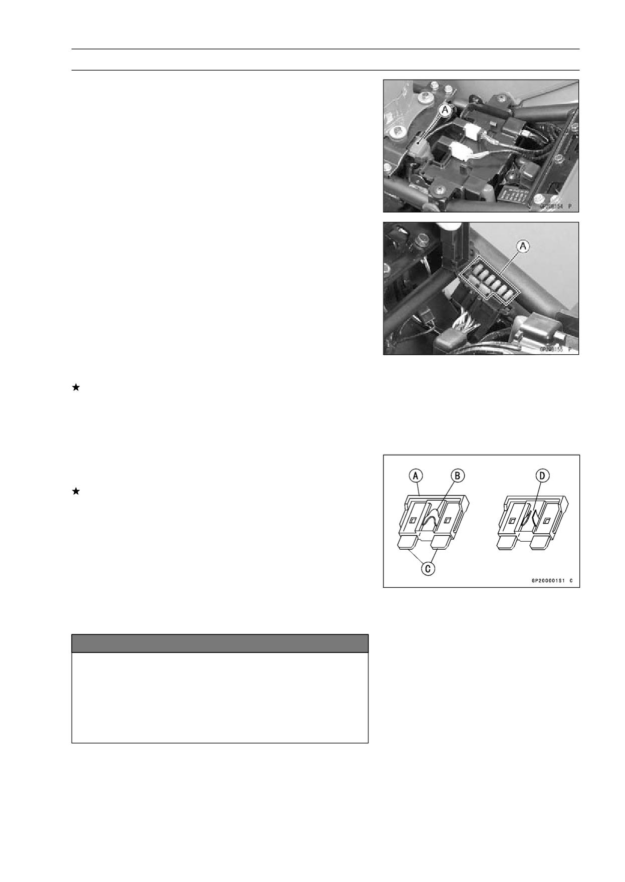
Fuses
30 A Main Fuse Removal
• Remove the front seat (see Front Seat Removal in the
Frame chapter).
• Unlock the hook to clear the lids of the main fuse cover
[A].
• Pull up the main fuse cover with the starter relay connec-
tor.
Fuse Removal
• Remove the front seat (see Front Seat Removal in the
Frame chapter).
• Unlock the hook to lift up the lid from the fuse case.
• Pull the fuses [A] straight up from the fuse case with the
nose plier.
Fuse Installation
If a fuse fails during operation, inspect the electrical sys-
tem to determine the cause, and then replace it with a
new fuse of proper amperage.
• Install the junction box fuses on the original position as
specified on the lid.
Fuse Inspection
• Remove the fuse, and inspect the fuse element.
If the fuse element is blown, replace the fuse.
Housing [A]
Fuse Element [B]
Terminal [C]
Blown Element [D]
NOTE
○Before replacing a blown fuse, always check the am-
perage in the affected circuit. If the amperage is equal
to or greater than the fuse rating, check the wiring and
related components for a short circuit.
NOTICE
When replacing a fuse, be sure the new fuse
matches the specified fuse rating for that circuit.
Installation of a fuse with a higher rating may cause
damage to wiring ad components, and installation
of a fuse with a lower rating may cause the fuse to
be blown quickly.
APPENDIX 17-1
Appendix
Table of Contents
Cable, Wire, and Hose Routing
17-2
Troubleshooting Guide
17-40
17
17-2 APPENDIX
Cable, Wire, and Hose Routing
APPENDIX 17-3
Cable, Wire, and Hose Routing
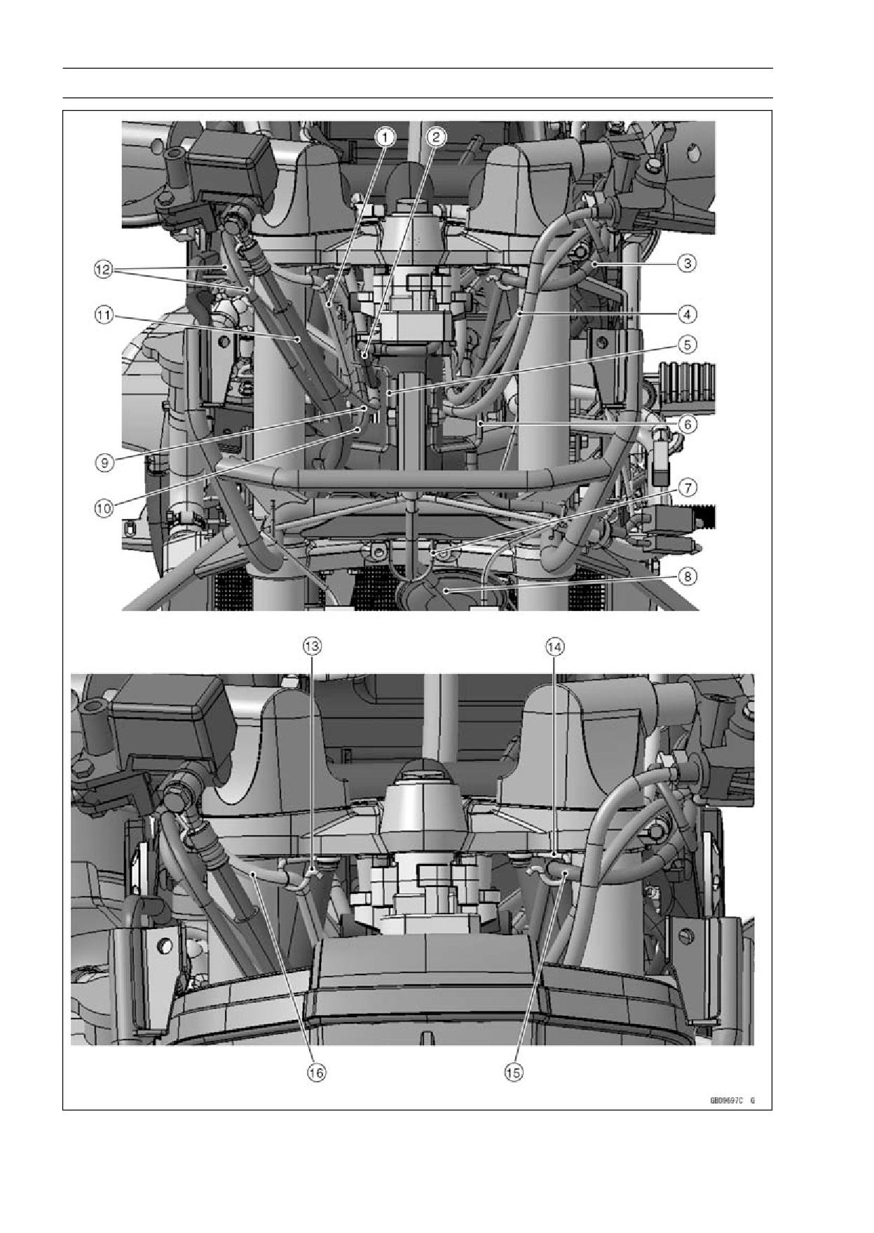
1. Right Switch Housing Leads
2. Ignition Switch Leads
3. Left Switch Housing Leads
4. Choke Cable
5. Guide
6. Guide
7. Guide
8. Speedometer Cable
9. Throttle Cable (Accelerator)
10. Throttle Cable (Decelerator)
11. Brake Hose
12. Throttle Cables
13. Guide
14. Guide
15. Left Switch Housing Leads
16. Right Switch Housing Leads
17-4 APPENDIX
Cable, Wire, and Hose Routing
APPENDIX 17-5
Cable, Wire, and Hose Routing
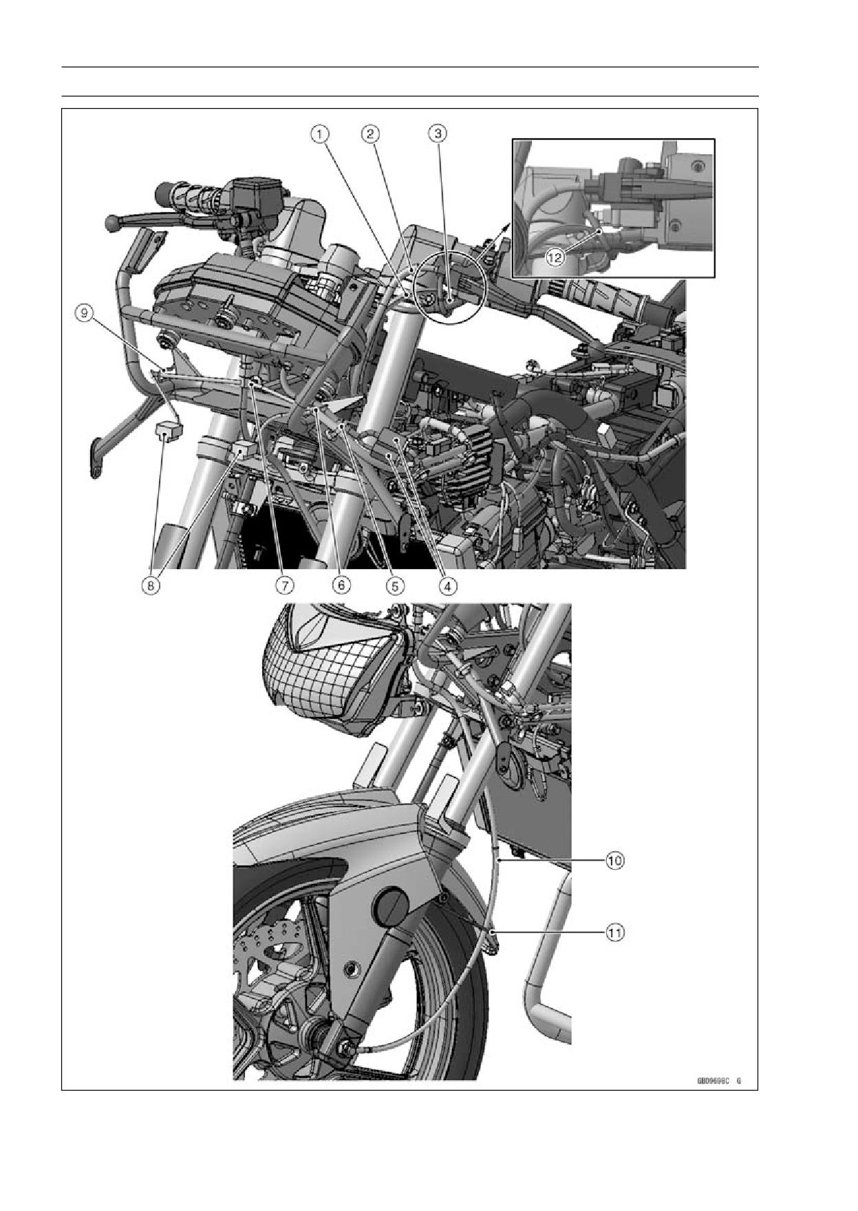
1. Choke Cable
2. Clutch Cable
3. Left Switch Housing Leads
4. Meter Leads Connectors
5. Band
6. Guide
7. Band
8. Headlight Leads Connectors
9. Guide
10. Speedometer Cable
11. Guide
12. Starter Locknut Switch Lead
17-6 APPENDIX
Cable, Wire, and Hose Routing
APPENDIX 17-7
Cable, Wire, and Hose Routing
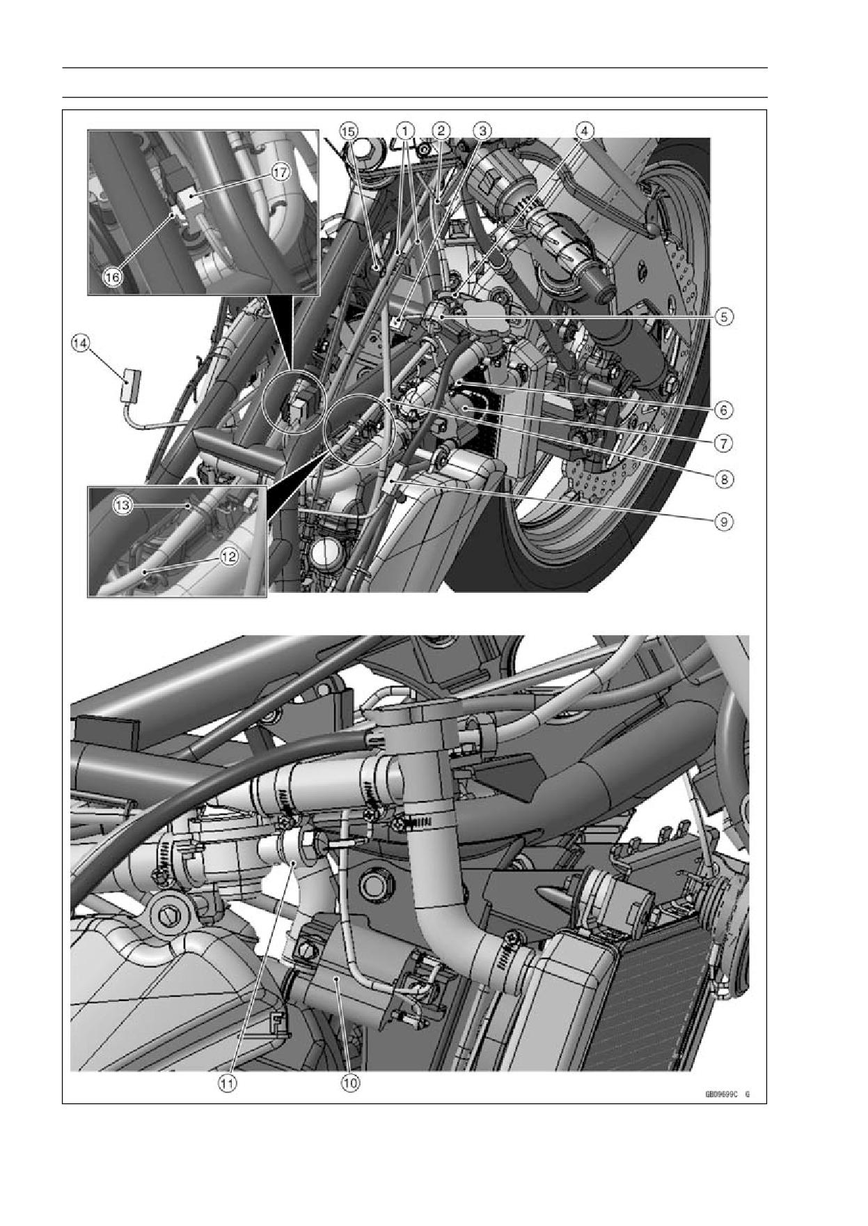
1. Throttle Cables
2. Guide
3. Radiator Fan Leads Connectors
4. Clamp
5. Right Switch Housing Leads
6. Water Temperature Switch
7. #2 Ignition Coil
8. Clutch Cable
9. Front Right Turn Signal Light Connector
10. #2 Ignition Coil
11. Water Temperature Switch
12. Main Harness
13. Guide
14. Front Left Turn Signal Light Connector
15. Bracket
16. Bracket
17. Ignition Switch Leads Connector
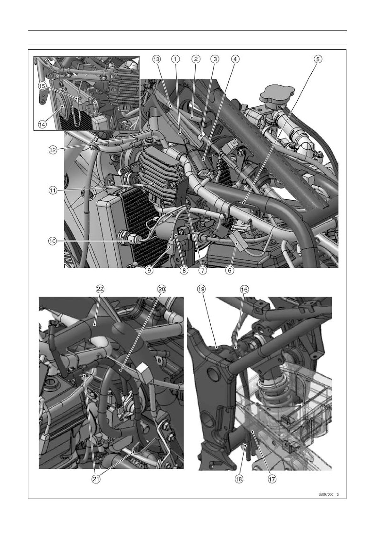
17-8 APPENDIX
Cable, Wire, and Hose Routing
APPENDIX 17-9
Cable, Wire, and Hose Routing
1. Left Switch Housing Leads
2. Clutch Cable
3. Clamp
4. Left Switching Housing Leads Connector
5. Guide
6. Front Left Turn Signal Light Connector
7. Guide
8. #1 Ignition Coil
9. Oil Pressure Switch Connector
10. Radiator Fan Switch
11. Radiator/Rectifier
12. Guide
13. Choke Cable
14. Horn
15. Guide
16. Guide
17. Coolant Reserver Tank Breather Hose
18. Guide
19. Fuel Tank Tank Breather Hose
20. Fuel Tank Tank Breather Hose
21. Guide
22. Guide
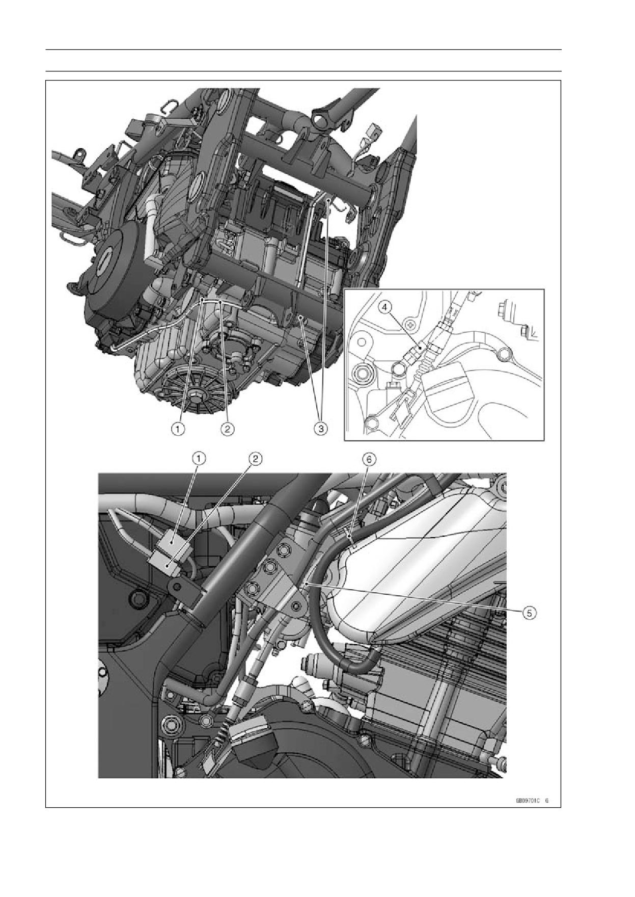
17-10 APPENDIX
Cable, Wire, and Hose Routing
APPENDIX 17-11
Cable, Wire, and Hose Routing
1. Alternator Leads
2. Crankshaft Sensor Leads
3. Brackets
4. Engine Ground Lead
5. Clutch Cable
6. Guide
17-12 APPENDIX
Cable, Wire, and Hose Routing
APPENDIX 17-13
Cable, Wire, and Hose Routing
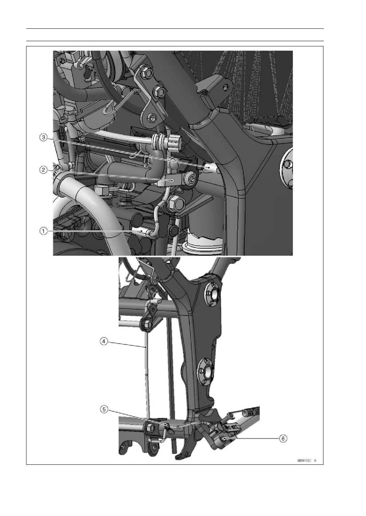
1. Neutral Switch Connector
2. Clamp
3. Sidestand Switch Connector
4. Sidestand Switch Leads
5. Clamp
6. Sidestand Switch
17-14 APPENDIX
Cable, Wire, and Hose Routing
APPENDIX 17-15
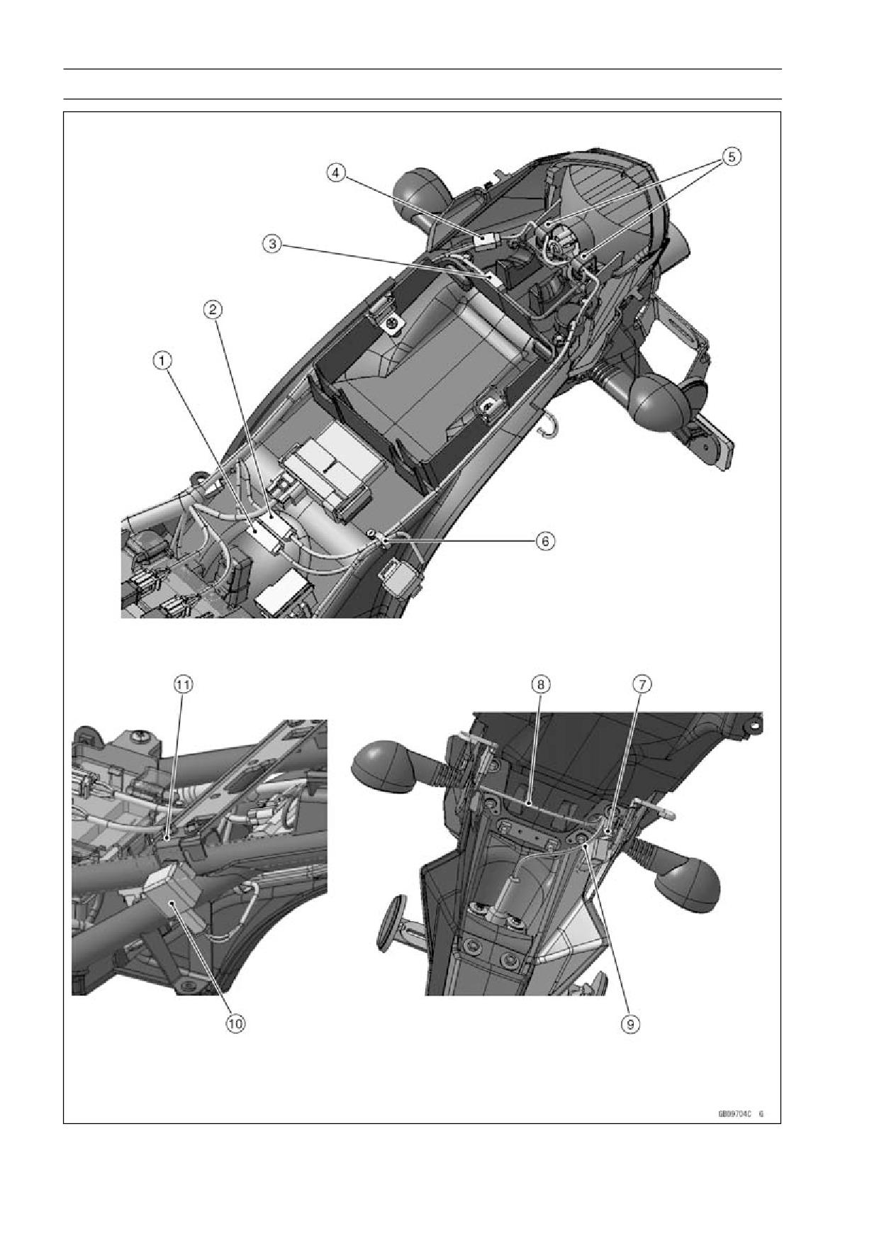
Cable, Wire, and Hose Routing
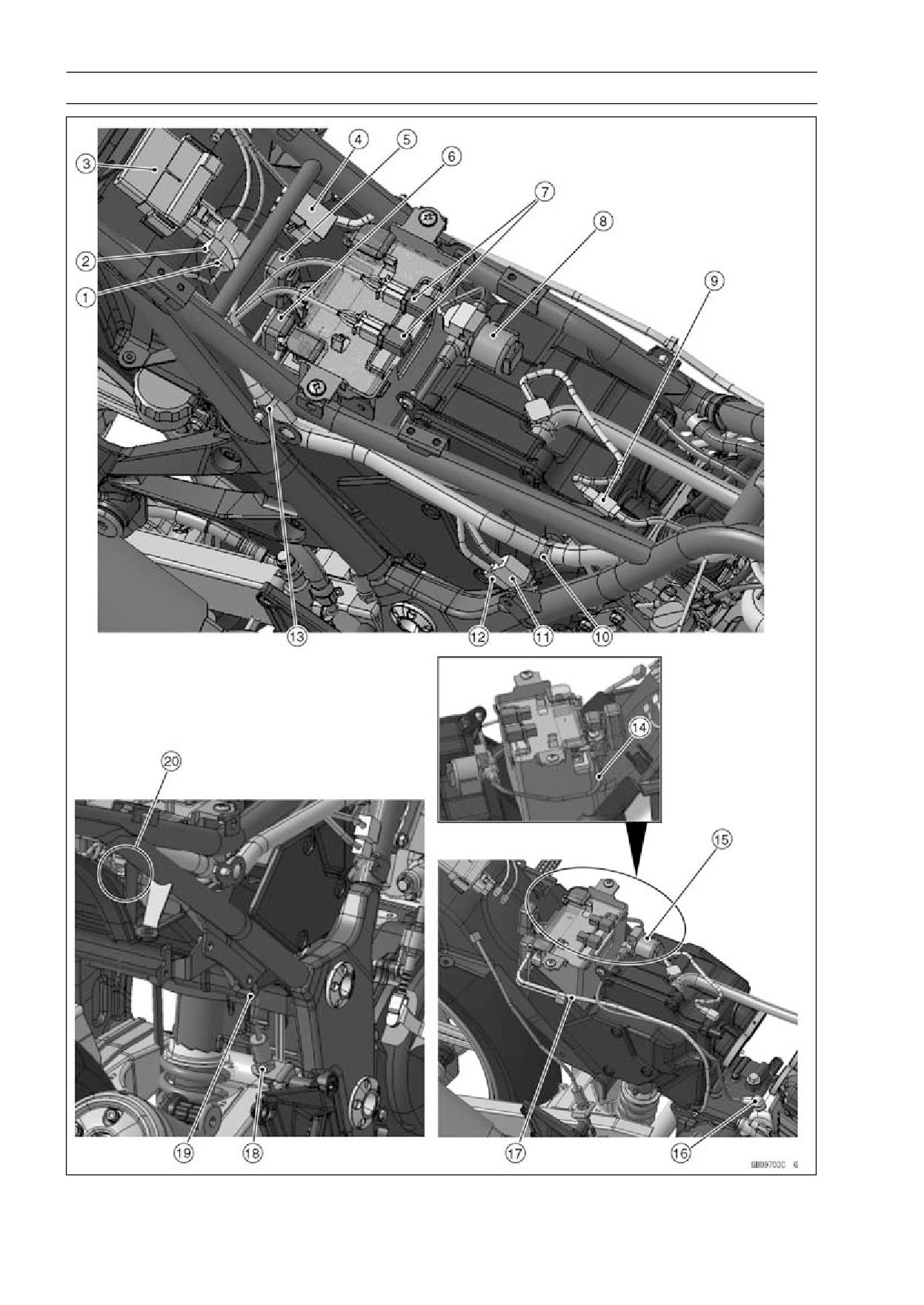
1. Rear Left Turn Signal Light Connector
2. Rear Right Turn Signal Light Connector
3. IC Igniter
4. Fuse Box
5. Headlight Circuit Relay
6. Starter Circuit Relay
7. Diodes
8. Starter Relay
9. Fuel Level Sensor Connector
10. Clamp
11. Alternator Connector
12. Crankshaft Connector
13. Clamp
14. Battery (+) Cable
15. Starter Relay
16. Starter Motor Cable
17. Battery (-) Cable
18. Rear Brake Switch
19. Clamp
20. Rear Brake Switch Connector
17-16 APPENDIX
Cable, Wire, and Hose Routing
APPENDIX 17-17
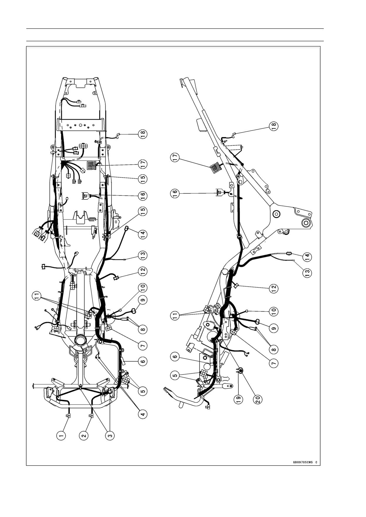
Cable, Wire, and Hose Routing
1. Rear Left Turn Signal Light Connector
2. Rear Right Turn Signal Light Connector
3. Brake/Tail Light Connector
4. License Plate Light Connector
5. Clamps
6. Clamp
7. Rear Left Turn Signal Light Connector
8. Rear Right Turn Signal Light Connector
9. License Plate Light Connector
10. Turn Signal Relay
11. Bracket
17-18 APPENDIX
Cable, Wire, and Hose Routing
APPENDIX 17-19
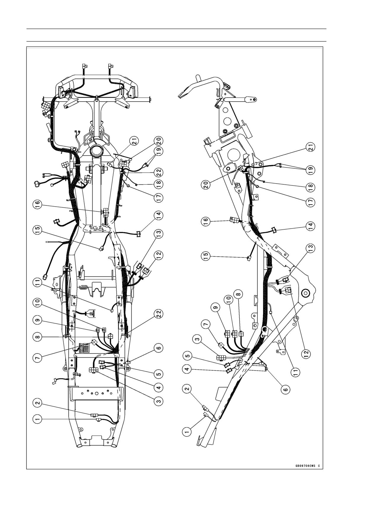
Cable, Wire, and Hose Routing
1. Headlight (High) Connector
2. Headlight (Low) Connector
3. Bands
4. Horn Connector
5. Meter Connector
6. Diode Connector
7. Regulator/Rectifier Connector
8. Ignition Coil Connector
9. Radiator Fan Switch Connector
10. Oil Pressure Switch Connector
11. Left Switch Housing Connectors
12. Front Turn Signal Light Connector
13. Neutral Switch Connector
14. Sidestand Switch Connector
15. Bands
16. Starter Relay
17. Fuse Box
18. Turn Signal Relay
19. Clamp
20. Choke Cable
17-20 APPENDIX
Cable, Wire, and Hose Routing
APPENDIX 17-21
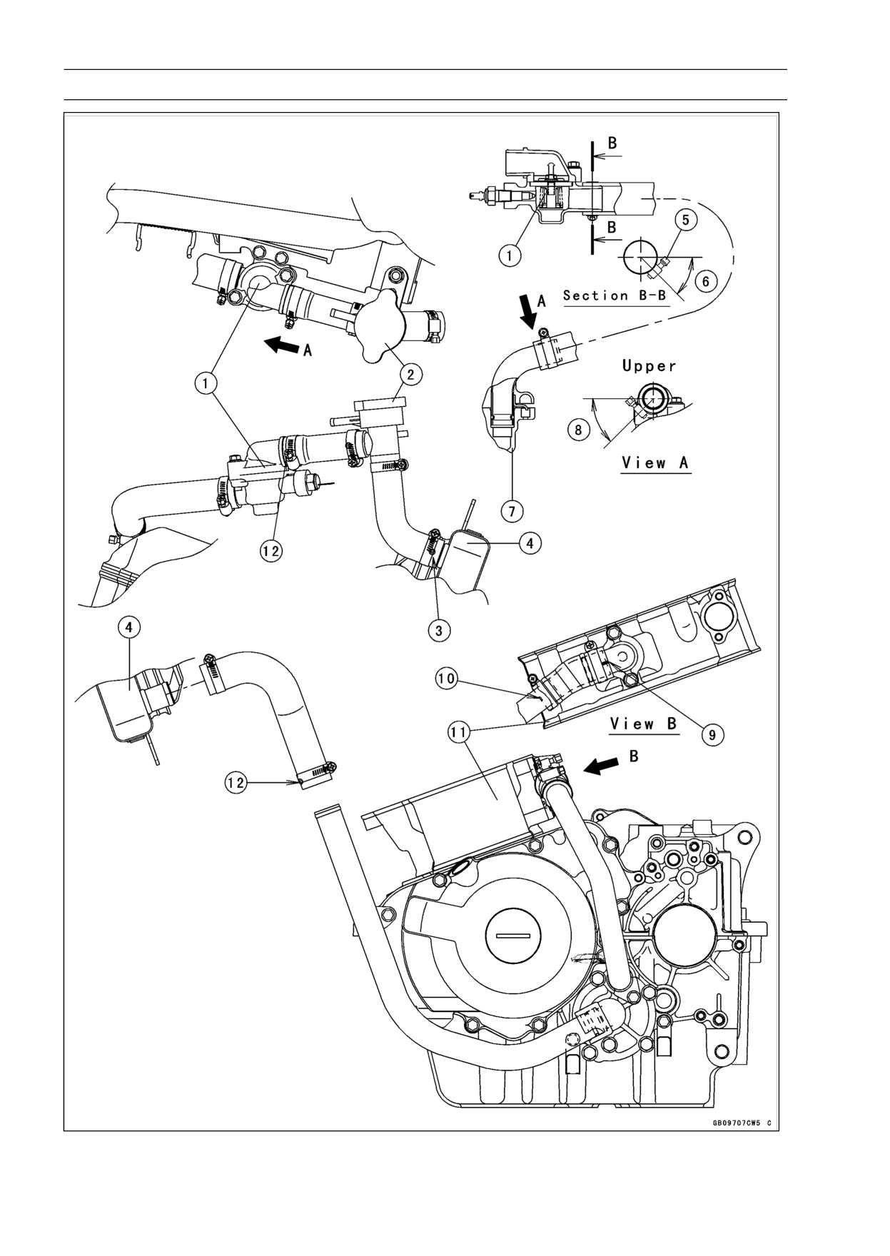
Cable, Wire, and Hose Routing
1. License Plate Light Connector
2. Tail/Brake Light Connector
3. IC Igniter Connector
4. Rear Right Turn Signal Light Connector
5. Rear Left Turn Signal Light Connector
6. Brake Light Switch Connector
7. Starter Relay Connector
8. Headlight Circuit Relay
9. Diode
10. Diode
11. Battery (-) Cable
12. Alternator Connector
13. Crankshaft Sensor Connector
14. Front Turn Signal Light Connector
15. Fuel Level Sensor Connector
16. Ignition Switch Connector
17. Frame Ground Terminal
18. Radiator Fan Switch Connector
19. Ignition Coil Connector
20. Right Switch Housing Connector
21. Radiator Fan Connector
22. Bands
17-22 APPENDIX
Cable, Wire, and Hose Routing
APPENDIX 17-23
Cable, Wire, and Hose Routing
1. Thermostat
2. Radiator Cap
3. Install the hose so that its white mark side faces the radiator.
4. Radiator
5. Clamp Screw
6. 45°
7. Cylinder Head
8. 45° ∼ 55°
9. Align the white mark on the hose with the projection mark on the fitting.
10. Install the hose so that its end cover the white mark on the pipe.
11. Cylinder
12. Install the hose so that its white mark side faces the pipe.
17-24 APPENDIX
Cable, Wire, and Hose Routing
APPENDIX 17-25
Cable, Wire, and Hose Routing
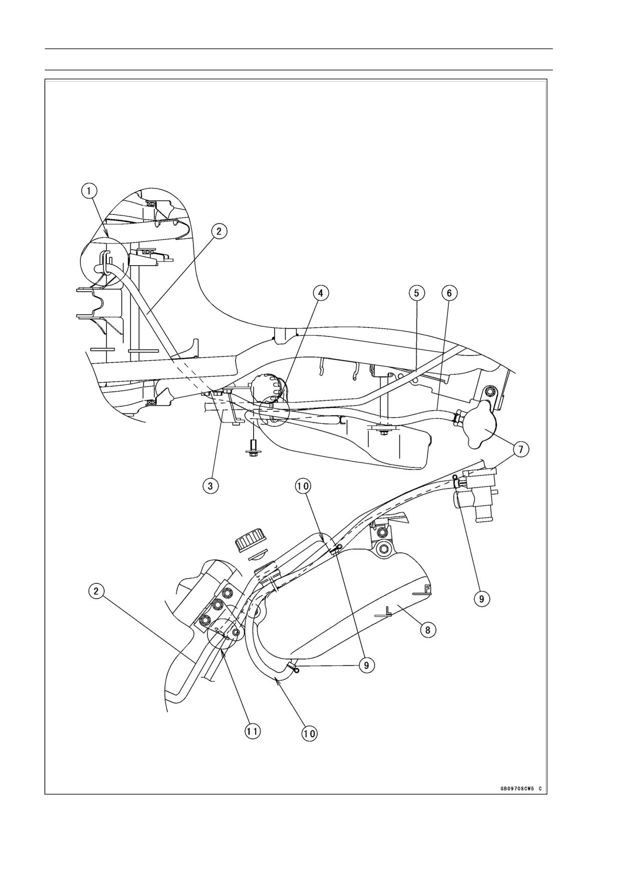
1. Run the reserver tank vent hose into the guide (2 places).
2. Reserver Tank Vent Hose
3. Bracket
4. Run the clutch cable and over flow hose into the hole of the reserver tank.
5. Clutch Cable
6. Radiator Overflow Hose
7. Radiator Cap
8. Coolant Reserver Tank
9. Clamp
10. Hose Curve Side
11. Run the only reserver tank vent hose into the bracket guide.
17-26 APPENDIX
Cable, Wire, and Hose Routing
APPENDIX 17-27
Cable, Wire, and Hose Routing
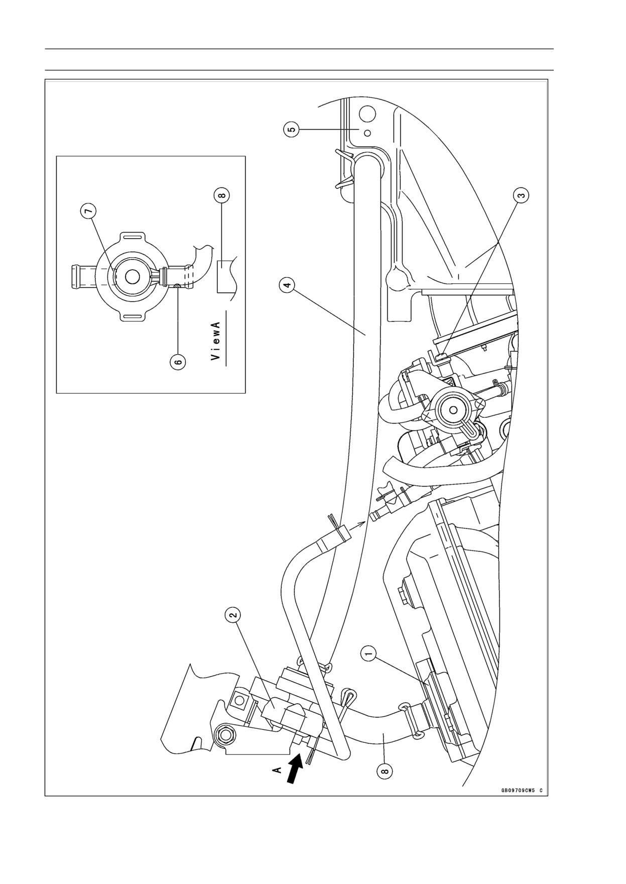
1. Air Suction Valve Cover
2. Vaccum Switch Valve
3. Carburetor
4. Install the vaccum switch valve hose so that its white mark faces the air cleaner box.
5. Air Cleaner Box
6. Install the vaccum valve switch fitting so that its white mark side faces the air suction valve hose.
7. This side is closed.
8. Air Suction Valve Hose
17-28 APPENDIX
Cable, Wire, and Hose Routing
APPENDIX 17-29
Cable, Wire, and Hose Routing
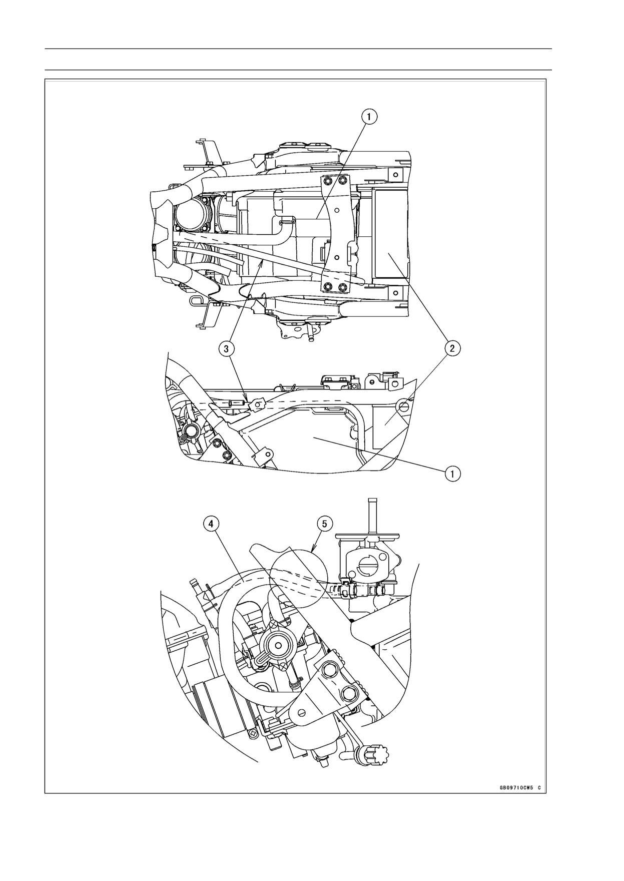
1. Air Cleaner Box
2. Battery
3. Run the carburetor vent hose between the air cleaner box and battery.
4. Fuel Hose
5. Run the fuel hose inside of the frame.
17-30 APPENDIX
Cable, Wire, and Hose Routing
APPENDIX 17-31
Cable, Wire, and Hose Routing
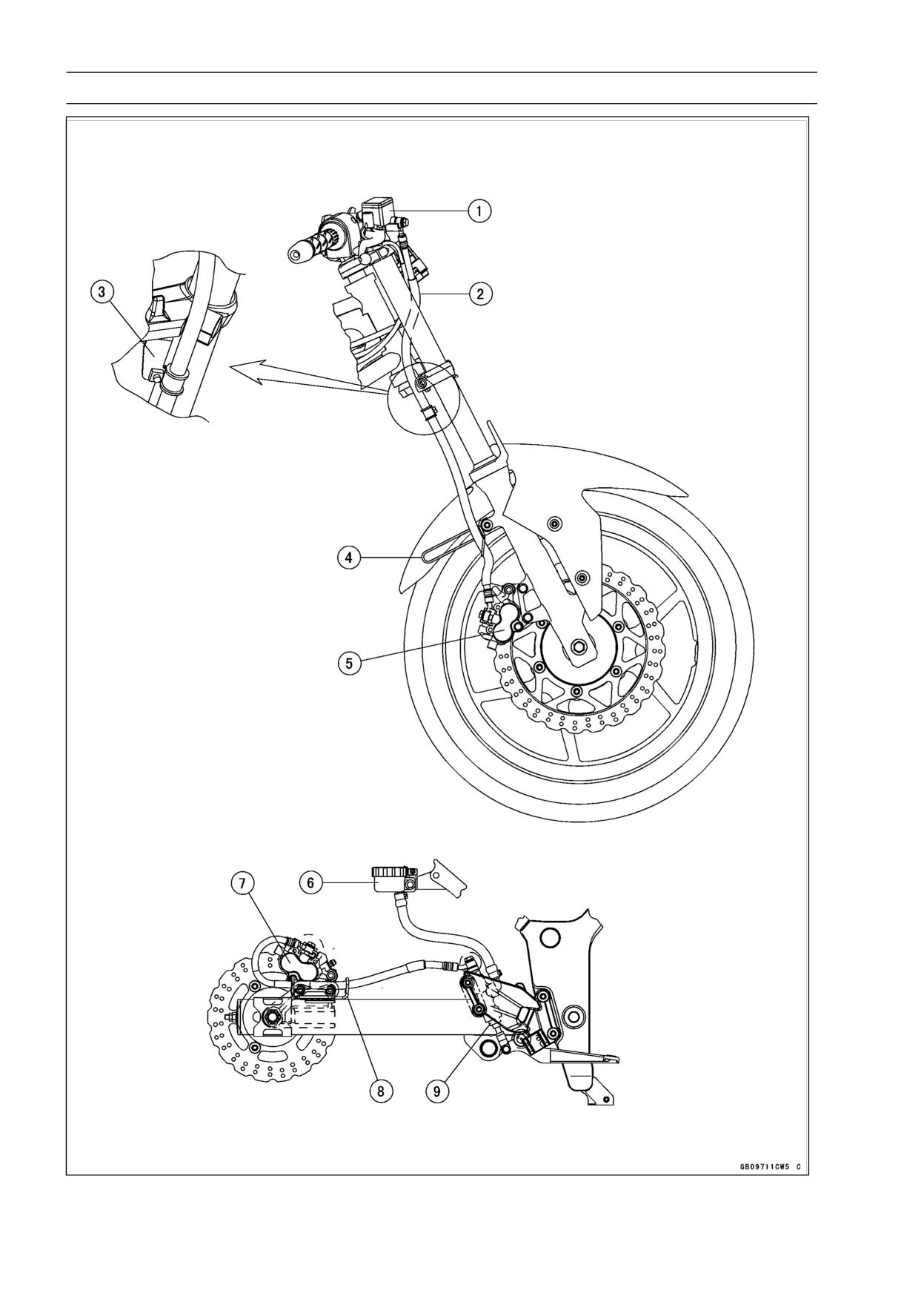
1. Front Master Cylinder
2. Front Brake Hse
3. Bracket
4. Clamp
5. Front Brake Caliper
6. Rear Brake Resevvoir
7. Rear Brake Caliper
8. Clamp
9. Rear Master Cylinder
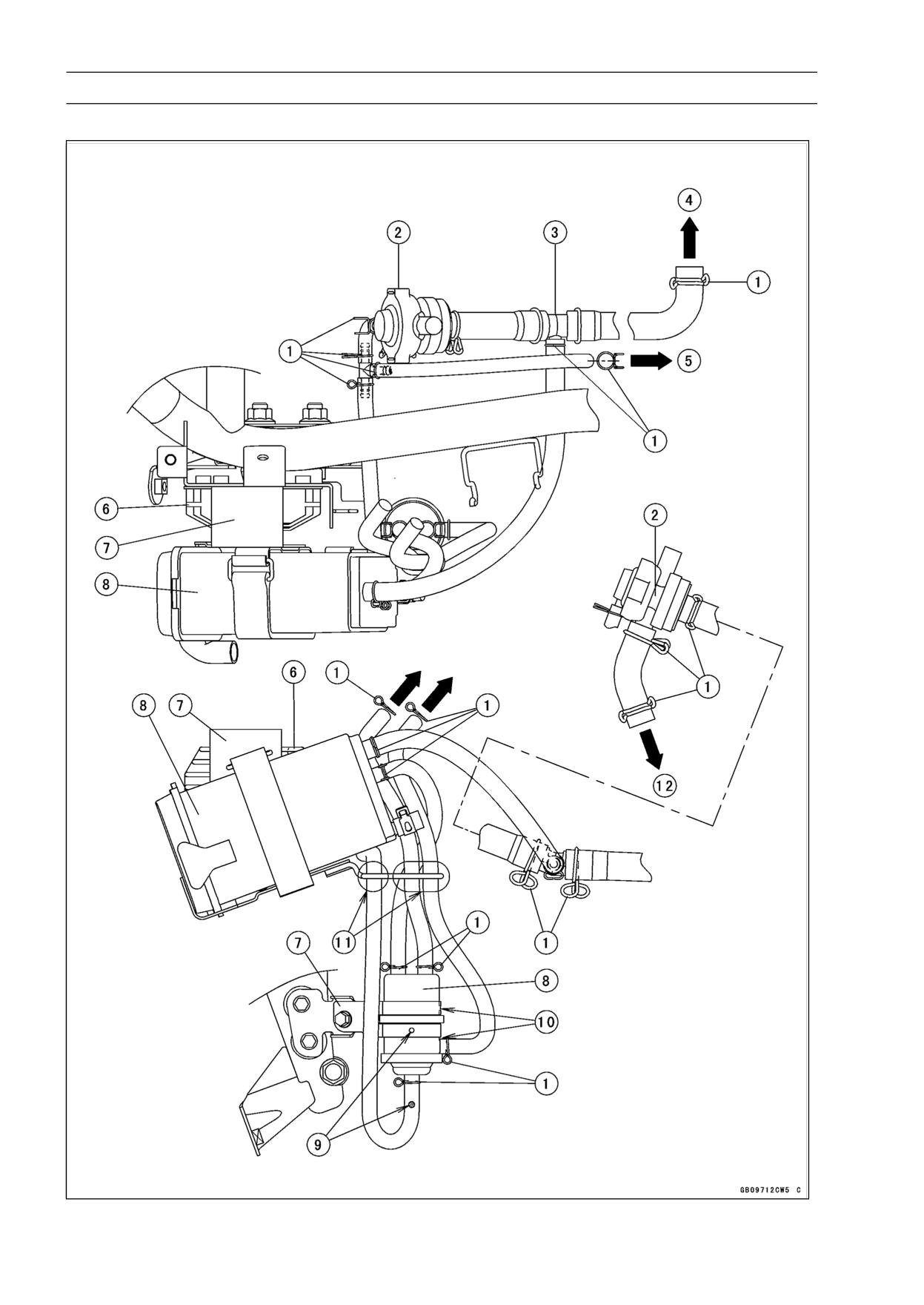
17-32 APPENDIX
Cable, Wire, and Hose Routing
California Model (EX250J8)
APPENDIX 17-33
Cable, Wire, and Hose Routing
1. Install the clamps as shown, noting their clip direction.
2. Vaccum Switch Valve
3. Fitting
4. To Air Cleaner Box
5. To Carburetor
6. Regulator/Rectifier
7. Bracket
8. Canister
9. Align the hole on the separator with the white mark on the hose.
10. Align the hole on the separator with the hose direction.
11. Run the hoses through the guide of the bracket.
12. To Air Suction Valve Cover.
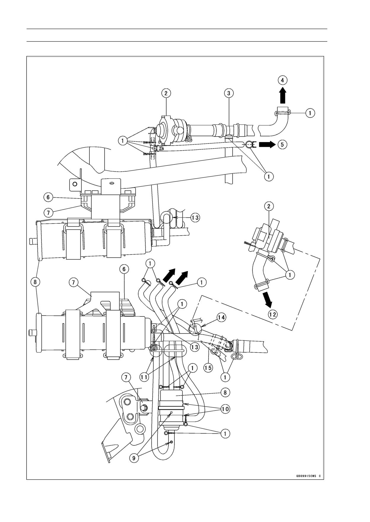
17-34 APPENDIX
Cable, Wire, and Hose Routing
California Model (EX250J9 ∼ JC)
APPENDIX 17-35
Cable, Wire, and Hose Routing
1. Install the clamps as shown, noting their clip direction.
2. Vaccum Switch Valve
3. Fitting
4. To Air Cleaner Box
5. To Carburetor
6. Regulator/Rectifier
7. Bracket
8. Canister
9. Align the hole on the separator with the white mark on the hose.
10. Align the hole on the separator with the hose direction.
11. Run the hoses through the guide of the bracket.
12. To Air Suction Valve Cover.
13. Run the hose through the clamp as shown.
14. Run the hose through the clamp.
15. Drain Hose.
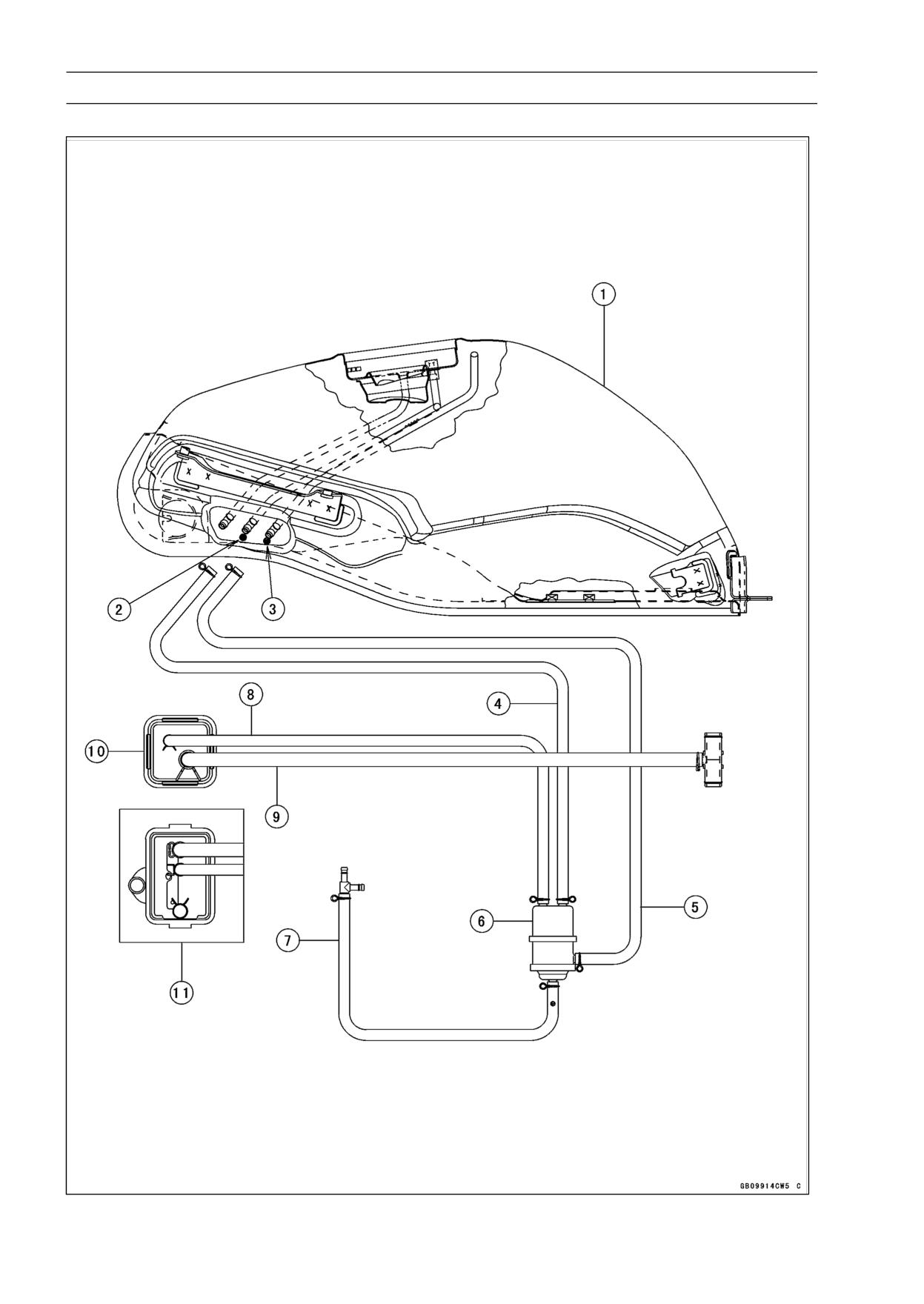
17-36 APPENDIX
Cable, Wire, and Hose Routing
California Model
APPENDIX 17-37
Cable, Wire, and Hose Routing
1. Fuel Tank
2. Blue Mark
3. Red Mark
4. Hose (Blue)
5. Hose (Red)
6. Separator
7. Hose (White)
8. Hose (Green)
9. Hose (Blue)
10. Canister
11. EX250J8
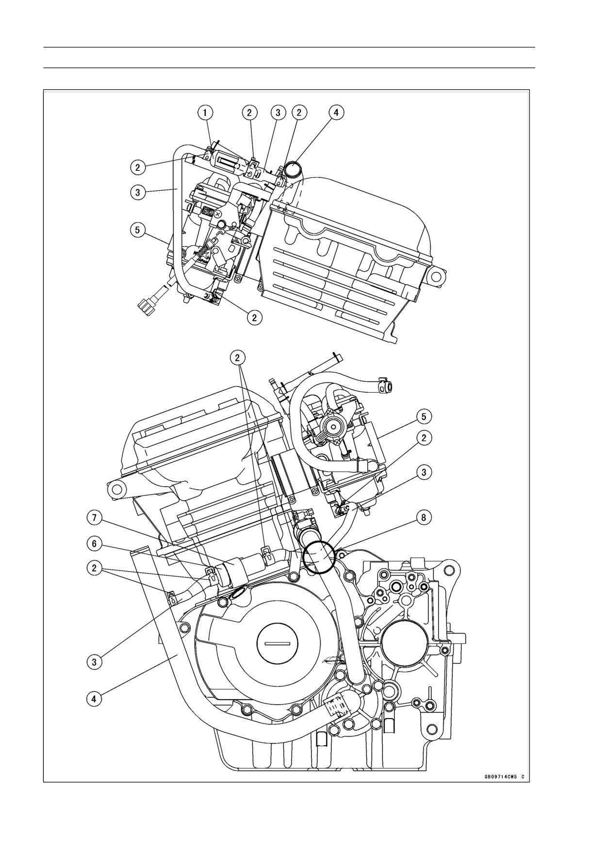
17-38 APPENDIX
Cable, Wire, and Hose Routing
Australia Model
APPENDIX 17-39
Cable, Wire, and Hose Routing
1. Filter Body
2. Clamps
3. Cooling Hose
4. Water Pipe
5. Carburetor
6. Coolant Valve Assmbly
7. Damper
8. Run the cooling hose inside of the water pipe.
17-40 APPENDIX
Troubleshooting Guide
NOTE
Crankshaft sensor trouble
○This is not an exhaustive list, giving every
Ignition coil trouble
possible cause for each problem listed. It
Ignition or engine stop switch shorted
is meant simply as a rough guide to assist
Wiring shorted or open
the troubleshooting for some of the more
Main fuse blown
common difficulties.
Compression Low:
Spark plug loose
Engine Doesn’t Start, Starting
Cylinder head not sufficiently tightened
Difficulty:
down
Starter motor not rotating:
No valve clearance
Starter lockout switch or neutral switch trou-
Cylinder, piston worn
ble
Piston ring bad (worn, weak, broken, or
Starter motor trouble
sticking)
Battery voltage low
Piston ring/groove clearance excessive
Starter relays not contacting or operating
Cylinder head gasket damaged
Starter button not contacting
Cylinder head warped
Wiring open or shorted
Valve spring broken or weak
Ignition switch trouble
Valve not seating properly (valve bent,
Engine stop switch trouble
worn, or carbon accumulation on the
Main fuse blown
seating surface)
Starter motor rotating but engine doesn’t
Fuel/air mixture incorrect:
turn over:
Pilot screw or idle adjusting screw malad-
Starter motor clutch trouble
justed
Engine won’t turn over:
Pilot jet or air bleed hole clogged
Valve seizure
Air cleaner clogged, poorly sealed, element
Valve lifter seizure
missing
Cylinder, piston seizure
Starter jet clogged
Crankshaft seizure
Connecting rod small end seizure
Poor Running at Low Speed:
Connecting rod big end seizure
Spark weak:
Transmission gear or bearing seizure
Battery voltage low
Camshaft seizure
Spark plug dirty, broken, or maladjusted
Starter idle gear seizure
Spark plug cap or high tension wiring trou-
No fuel flow:
ble
No fuel in fuel tank
Spark plug cap shorted or not in good con-
Fuel tap vacuum hose clogged
tact
Fuel tank air vent obstructed
Spark plug incorrect
Fuel tap clogged
IC igniter trouble
Fuel line clogged
Crankshaft sensor trouble
Float valve clogged
Ignition coil trouble
Engine flooded:
Fuel/air mixture incorrect:
Fuel level in carburetor float bowl too high
Pilot screw maladjusted
Float valve worn or stuck open
Pilot jet, or air passage clogged
Starting technique faulty (When flooded,
Air bleed pipe bleed holes clogged
crank the engine with the throttle fully
Pilot passage clogged
opened to allow more air to reach the
Air cleaner clogged, poorly sealed, or ele-
engine.)
ment missing
No spark; spark weak:
Choke plunger stuck open
Battery voltage low
Fuel level in carburetor float bowl too high
Spark plug dirty, broken, or maladjusted
or too low
Spark plug cap or high tension wiring trou-
Fuel tank air vent obstructed
ble
Carburetor holder loose
Spark plug cap not in good contact
Air cleaner duct loose
Spark plug incorrect
Compression low:
IC igniter trouble
Spark plug loose
Neutral, starter lockout, or sidestand switch
Cylinder head not sufficiently tightened
trouble
down
APPENDIX 17-41
Troubleshooting Guide
No valve clearance
Cylinder head warped
Cylinder, piston worn
Valve spring broken or weak
Piston ring bad (worn, weak, broken, or
Valve not seating properly (valve bent,
sticking)
worn, or carbon accumulation on the
Piston ring/groove clearance excessive
seating surface.)
Cylinder head warped
Knocking:
Cylinder head gasket damaged
Carbon built up in combustion chamber
Valve spring broken or weak
Fuel poor quality or incorrect
Valve not seating properly (valve bent,
Spark plug incorrect
worn, or carbon accumulation on the
IC igniter trouble
seating surface)
Miscellaneous:
Other:
Throttle valve won’t fully open
IC igniter trouble
Vacuum piston doesn’t slide smoothly
Carburetor not synchronizing
Brake dragging
Vacuum piston doesn’t slide smoothly
Clutch slipping
Engine oil viscosity too high
Overheating
Drive train trouble
Engine oil level too high
Brake dragging
Engine oil viscosity too high
Drive train trouble
Poor Running or No Power at High
Speed:
Overheating:
Firing incorrect:
Firing incorrect:
Spark plug dirty, broken, or maladjusted
Spark plug dirty, broken, or maladjusted
Spark plug cap shorted or not in good con-
Spark plug incorrect
tact
IC Igniter trouble
Spark plug incorrect
Fuel/air mixture incorrect:
IC igniter trouble
Main jet clogged or wrong size
Crankshaft sensor trouble
Fuel level in carburetor float bowl too low
Ignition coil trouble
Carburetor holder loose
Fuel/air mixture incorrect:
Air cleaner poorly sealed, or missing
Choke plunger stuck open
Air cleaner duct poorly sealed
Main jet clogged or wrong size
Air cleaner clogged
Jet needle or needle jet worn
Compression high:
Air jet clogged
Carbon built up in combustion chamber
Fuel level in carburetor float bowl too high
Engine load faulty:
or too low
Clutch slipping
Bleed holes of needle jet holder or needle
Engine oil level too high
jet clogged
Engine oil viscosity too high
Air cleaner clogged, poorly sealed, or miss-
Drive train trouble
ing
Brake dragging
Air cleaner duct poorly sealed
Lubrication inadequate:
Water or foreign matter in fuel
Engine oil level too low
Fuel to carburetor insufficient
Engine oil poor quality or incorrect
Fuel tank air vent obstructed
Coolant incorrect:
Carburetor holder loose
Coolant level too low
Fuel tap clogged
Coolant deteriorated
Fuel line clogged
Cooling system component incorrect:
Compression low:
Radiator fin damaged
Spark plug loose
Thermostat trouble
Cylinder head not sufficiently tightened
Radiator cap trouble
down
Radiator fan switch trouble
No valve clearance
Fan relay trouble
Cylinder, piston worn
Fan motor broken
Piston ring bad (worn, weak, broken, or
Fan blade damaged
sticking)
Water pump not turning
Piston ring/groove clearance excessive
Water pump impeller damaged
Cylinder head gasket damaged
17-42 APPENDIX
Troubleshooting Guide
Over Cooling:
Abnormal Engine Noise:
Cooling system component incorrect:
Knocking:
Radiator fan switch trouble
IC igniter trouble
Thermostat trouble
Carbon built up in combustion chamber
Gauge incorrect:
Fuel poor quality or incorrect
Water temperature gauge broken
Spark plug incorrect
Water temperature sensor broken
Overheating
Piston slap:
Clutch Operation Faulty:
Cylinder/piston clearance excessive
Clutch slipping:
Cylinder, piston worn
Friction plate worn or warped
Connecting rod bent
Steel plate worn or warped
Piston pin, piston pin hole worn
Clutch inner cable trouble
Valve noise:
No clutch lever play
Valve clearance incorrect
Clutch spring broken or weak
Valve spring broken or weak
Clutch release mechanism trouble
Camshaft bearing worn
Clutch hub or housing unevenly worn
Other noise:
Clutch not disengaging properly:
Connecting rod small end clearance exces-
Clutch plate warped or too rough
sive
Clutch spring compression uneven
Connecting rod big end clearance exces-
Engine oil deteriorated
sive
Engine oil viscosity too high
Piston ring worn, broken, or stuck
Engine oil level too high
Piston seizure, damage
Clutch housing frozen on drive shaft
Piston ring groove worn
Clutch release mechanism trouble
Piston ring/groove clearance excessive
Clutch hub spline damaged
Cylinder head gasket leaking
Clutch friction plate installed wrong
Exhaust pipe leaking at cylinder head con-
Clutch lever play excessive
nection
Clutch hub nut loose
Crankshaft runout excessive
Engine mounts loose
Gear Shifting Faulty:
Crankshaft bearing worn
Doesn’t go into gear; shift pedal doesn’t
Camshaft chain tensioner trouble
return:
Camshaft chain, sprocket, guide worn
Clutch not disengaging
Alternator rotor loose
Shift fork bent or seized
Primary gear worn or broken
Gear stuck on the shaft
Shift return spring weak or broken
Abnormal Drive Train Noise:
Shift return spring pin loose
Clutch noise:
Pawl spring broken
Weak or damaged damper
Shift mechanism arm broken
Clutch housing/friction plate clearance ex-
Shift pawl broken
cessive
Jumps out of gear:
Clutch housing gear worn
Shift fork ear worn
Transmission noise:
Gear groove worn
Bearings worn
Gear dogs and/or dog holes worn
Transmission gears worn or chipped
Shift drum groove worn
Metal chips jammed in gear teeth
Neutral positioning pin spring weak or bro-
Engine oil insufficient
ken
Drive line noise:
Shift fork guide pin worn
Drive chain adjusted improperly
Drive shaft, output shaft, and/or gear
Drive chain worn
splines worn
Rear and/or engine sprocket worn
Overshifts:
Chain lubrication insufficient
Neutral positioning lever spring weak or
Rear wheel misaligned
broken
Pawl spring broken
Abnormal Frame Noise:
Front fork noise:
Oil insufficient or too thin
APPENDIX 17-43
Troubleshooting Guide
Spring weak or broken
Handlebar shakes or excessively vibrates:
Rear shock absorber noise:
Tire worn
Shock absorber damaged
Swingarm pivot bearings worn
Disc brake noise:
Rim warped, or not balanced
Pad installed incorrectly
Wheel bearing worn
Pad surface glazed
Handlebar clamp bolts loose
Disc warped
Steering stem head nut loose
Caliper trouble
Front/rear axle runout too large
Other noise:
Handlebar pulls to one side:
Bracket, nut, bolt, etc.
not properly
Frame bent
mounted or tightened
Wheel misalignment
Swingarm bent or twisted
Oil Pressure Warning Light Goes On:
Steering maladjusted
Engine oil pump damaged
Front fork bent
Engine oil screen clogged
Right and left front fork oil level uneven
Engine oil level too low
Shock absorption unsatisfactory:
Engine oil viscosity too low
(Too hard)
Camshaft bearing worn
Front fork oil excessive
Crankshaft bearings worn
Front fork oil viscosity too high
Oil pressure switch damaged
Rear shock absorber adjustment too hard
Wiring faulty
Tire air pressure too high
Relief valve stuck open
Front fork bent
O-ring at the oil passage in the crankcase
(Too soft)
damaged
Front fork oil insufficient and/or leaking
Engine oil filter clogged
Front fork oil viscosity too low
Front fork, rear shock absorber spring weak
Exhaust Smokes Excessively:
Rear shock absorber oil leaking
White smoke:
Rear shock absorber adjustment too soft
Piston oil ring worn
Tire air pressure too low
Cylinder worn
Valve oil seal damaged
Brake Doesn’t Hold:
Valve guide worn
Air in the brake line
Engine oil level too high
Pad or disc worn
Black smoke:
Brake fluid leakage
Air cleaner clogged
Disc warped
Main jet too large or fallen off
Contaminated pad
Choke plunger stuck open
Brake fluid deteriorated
Fuel level in carburetor float bowl too high
Primary or secondary cup damaged
Brown smoke:
Master cylinder scratched inside
Main jet too small
Fuel level in carburetor float bowl too low
Battery Trouble:
Air cleaner duct loose
Battery discharged:
Air cleaner poorly sealed or missing
Battery faulty (e.g., plates sulphated,
shorted through sedimentation, elec-
Handling and/or Stability
trolyte insufficient)
Unsatisfactory:
Battery cables making poor contact
Handlebar hard to turn:
Load excessive (e.g., bulb of excessive
Cable routing incorrect
wattage)
Hose routing incorrect
Ignition switch trouble
Wiring routing incorrect
Alternator trouble
Steering stem locknut too tight
Wiring faulty
Steering stem bearing damaged
Regulator/rectifier trouble
Steering stem bearing lubrication inade-
Battery overcharged:
quate
Regulator/rectifier trouble
Steering stem bent
Battery faulty
Tire air pressure too low
MODEL APPLICATION
Year
Model
Beginning Frame No.
2008
EX250J8
JKAEXMJ1□8DA00001
2009
EX250J9
JKAEXMJ1□9DA17355
2010
EX250JA
JKAEXMJ1□ADA49773
2011
EX250JB
JKAEXMJ1□BDA71588
2012
EX250JC
JKAEXMJ1□CDA96621
□:This digit in the frame number changes from one machine to another.
Part No.99924-1391-05
Printed in Japan