Kawasaki Ninja ZX-6R Motorcycle. Service Manual (2001-2002 year) - page 4
ELECTRICAL SYSTEM 15-29
Charging System
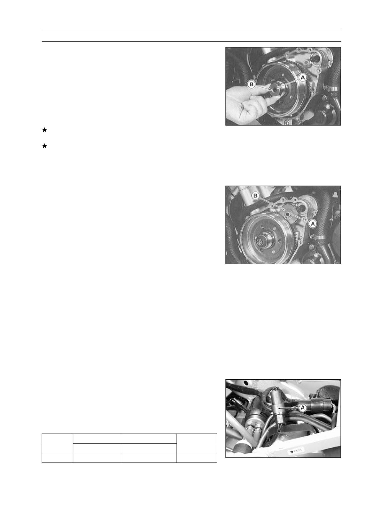
Install the washer [A] so that the chamfer side [B] faces
•
outward.
NOTE
○Confirm the alternator rotor fit or not to the crankshaft
before tightening it with specified torque.
○Install the rotor and tighten it with 70 N·m (7 kgf·m, 52
ft·lb) of torque.
○Remove the washer and rotor bolt.
○Check the tightening torque with rotor puller.
If the rotor is not pulled out with 20 N·m (2 kgf·m, 15 ft·lb)
of drawing torque, it is installed correctly.
If the rotor is pulled out with under 20 N·m (2 kgf·m, 15
ft·lb) of drawing torque, clean off any oil dirt or flaw of the
crankshaft and rotor tapered portion, and dry them with
a clean cloth. Then, confirm that it is not pulled out with
above torque.
Tighten the alternator rotor bolt while holding the alterna-
•
tor rotor steady with the flywheel holder.
Special Tool - Flywheel Holder: 57001-1313
Torque - Alternator Rotor Bolt: 120 N·m (12 kgf·m, 87 ft·lb)
Apply a thin coat of molybdenum disulfide grease to the
•
shaft [A], and install it and starter idle gear [B].
Install the alternator cover (see Alternator Cover Installa-
•
tion).
Alternator Inspection
There are three types of alternator failures: short, open
(wire burned out), or loss in rotor magnetism. A short or
open in one of the coil wires will result in either a low output,
or no output at all. A loss in rotor magnetism, which may be
caused by dropping or hitting the alternator, by leaving it
near an electromagnetic field, or just by aging, will result in
low output.
To check the alternator output voltage, do the following
•
procedures.
○Turn off the ignition switch.
○Remove the fuel tank (see Fuel System chapter).
○Supply fuel to the carburetors with an auxiliary fuel tank.
○Disconnect the alternator lead connector [A].
○Connect the hand tester as shown in the table 1.
○Start the engine, and run it 6,000 rpm 5 minutes.
○Run it at the rpm given in the table 1.
○Note the voltage readings (total 3 measurements).
Table 1 Alternator Output Voltage
Tester
Connections
Reading @
Range
Tester (+) to
Tester (-) to
4 000 rpm
250 V AC
One Black lead
Another Black lead
53.5 ∼ 72.5 V
15-30 ELECTRICAL SYSTEM
Charging System
If the output voltage shows the value in the table, the al-
ternator operates properly.
If the output voltage shows a much higher than the value
in the table, the regulator/rectifier is damaged. A much
lower reading than that given in the table indicates that
the alternator is defective.
Check the stator coil resistance as follows.
•
○Stop the engine.
○Connect the hand tester as shown in the table 2.
○Note the readings (total 3 measurement).
Table 2 Stator Coil Resistance
Tester
Connections
Reading
Range
Tester (+) to
Tester (-) to
× 1 Ω
One Black lead
Another Black lead
0.3 ∼ 0.4 Ω
If there is more resistance than shown in the table, or no
hand tester reading (infinity) for any two leads, the stator
has an open lead and must be replaced. Much less than
this resistance means the stator is shorted, and must be
replaced.
Using the highest resistance range of the hand tester,
•
measure the resistance between each of the black leads
and chassis ground.
Any hand tester reading less than infinity (∞) indicates a
short, necessitating stator replacement.
If the stator coils have normal resistance, but the voltage
check showed the alternator to be defective; then the rotor
magnets have probably weakened, and the rotor must be
replaced.
Special Tool - Hand Tester: 57001-1394
Regulator/Rectifier Inspection
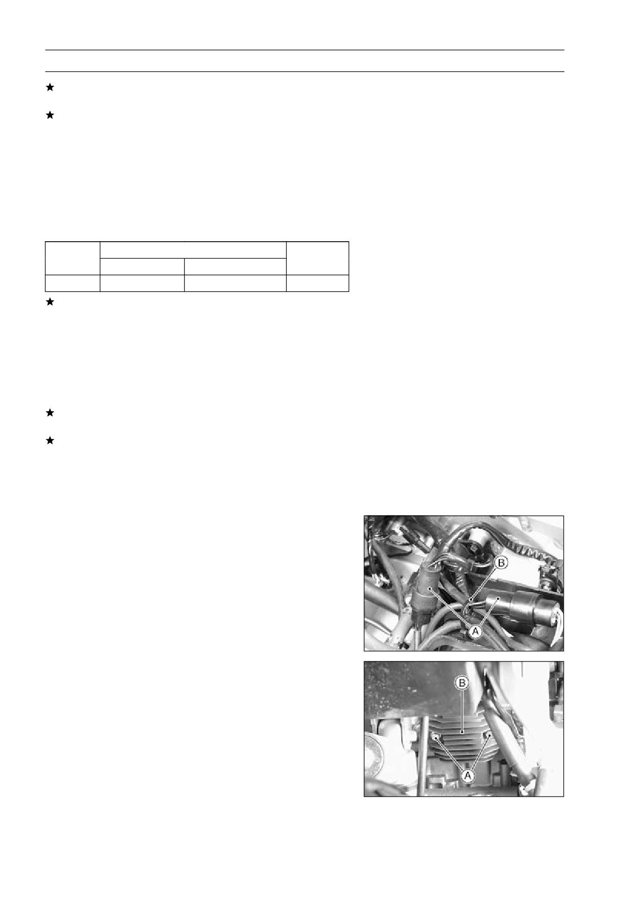
Remove:
•
Seat Cover (see Frame chapter)
Fuel Tank (see fuel System chapter)
Connectors [A] (disconnect)
Clamp [B]
Bolts [A]
Regulator/Rectifier [B]
ELECTRICAL SYSTEM 15-31
Charging System
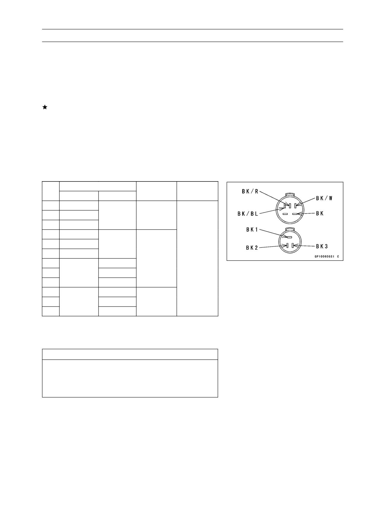
Rectifier Circuit Check
Check the rectifier resistance as follows.
•
Disconnect the regulator/rectifier connector.
•
Connect the hand tester (special tool) to the regulator/rec-
•
tifier as shown in the table, and check the resistance in
both directions of each diode in the rectifier following the
table.
The resistance should be low in one direction and more
than ten times as much in the other direction. If any two
leads are low or high in both directions, the rectifier is
defective and the regulator/rectifier must be replaced.
NOTE
○The actual meter reading varies with the meter used
and the individual rectifier, but, generally speaking the
lower reading should be from zero to one half the scale.
Connections
No.
Reading
Tester Range
Tester (+)
Tester (-)
1
BK1
2
BK2
BK/BL
∞
3
BK3
4
BK1
5
BK2
BK/W
6
BK3
× 10Ω
7
BK1
1/2 scale or
or
8
BK/BL
BK2
less
× 100Ω
9
BK3
10
BK1
11
BK/W
BK2
∞
12
BK3
Regulator Circuit Check
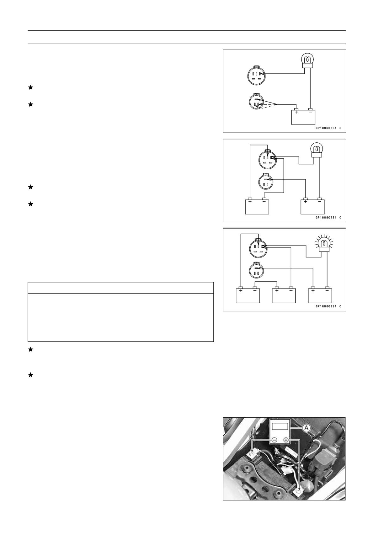
To test the regulator out of circuit, use three 12 V batteries
and a test light (12 V 3 ∼ 6 W bulb in a socket with leads).
CAUTION
The test light works as an indicator and also a cur-
rent limiter to protect the regulator/rectifier from ex-
cessive current. Do not use an ammeter instead of
a test light.
15-32 ELECTRICAL SYSTEM
Charging System
Do the 1st step regulator circuit test.
•
○Connect the test light and the 12 V battery to the regula-
tor/rectifier as shown.
○Check BK1, BK2, and BK3 terminal respectively.
If the test light turns on, the regulator/rectifier is defective.
Replace it.
If the test light does not turn on, continue the test.
Do the 2nd step regulator circuit test.
•
○Connect the test light and the 12 V battery in the same
manner as specified in the "1st step regulator circuit test".
○Apply 12 V to the BK/R terminal.
○Check BK1, BK2, and BK3 terminal respectively.
If the test light turns on, the regulator/rectifier is defective.
Replace it.
If the test light does not turn on, continue the test.
Do the 3rd step regulator circuit test
•
○Connect the test light and the 12 V battery in the same
manner as specified in the "1st step regulator circuit test".
○Momentarily apply 24 V to the BK/R terminal by adding a
12 V battery.
○Check BK1, BK2, and BK3 terminals respectively.
CAUTION
Do not apply more than 24 volts. If more than 24
volts is applied the regulator/rectifier may be dam-
aged. Do not apply 24 V more than a few seconds.
If 24 volts is applied for more than a few seconds,
the regulator/rectifier may be damaged.
If the test light did not light when the 24 V was applied
momentarily to the BK/R terminal, the regulator/rectifier
is defective. Replace it.
If the regulator/rectifier passes all of the tests described,
it may still be defective. If the charging system still does
not work properly after checking all of the components
and the battery, test the regulator/rectifier by replacing it
with a known good unit.
Charging Voltage Inspection
Check the battery condition (see Battery section).
•
Warm up the engine to obtain actual alternator operating
•
conditions.
Remove the seats (see Frame chapter).
•
Check that the ignition switch is turned off, and connect
•
the hand tester [A] as shown in the table.
Special Tool - Hand Tester: 57001-1394
ELECTRICAL SYSTEM 15-33
Charging System
Start the engine, and note the voltage readings at vari-
•
ous engine speeds with the headlight turned on and then
turned off. (To turn off the headlight of US , Canada, Aus-
tralia and Malaysia models, disconnect the headlight con-
nector in the upper fairing.) The readings should show
nearly battery voltage when the engine speed is low, and,
as the engine speed rises, the readings should also rise.
But they must be kept under the specified voltage.
Charging Voltage
Connections
Tester Range
Reading
Tester (+) to
Tester (-) to
25 V DC
Battery (+)
Battery (-)
14.2 ∼ 15.2 V
Turn off the ignition switch to stop the engine, and discon-
•
nect the hand tester.
If the charging voltage is kept between the values given in
the table, the charging system is considered to be working
normally.
If the charging voltage is much higher than the values
specified in the table, the regulator/rectifier is defective
or the regulator/rectifier leads are loose or open.
If the charging voltage does not rise as the engine speed
increases, then the regulator/rectifier is defective or the
alternator output is insufficient for the loads. Check the
alternator and regulator/rectifier to determine which part
is defective.
15-34 ELECTRICAL SYSTEM
Charging System
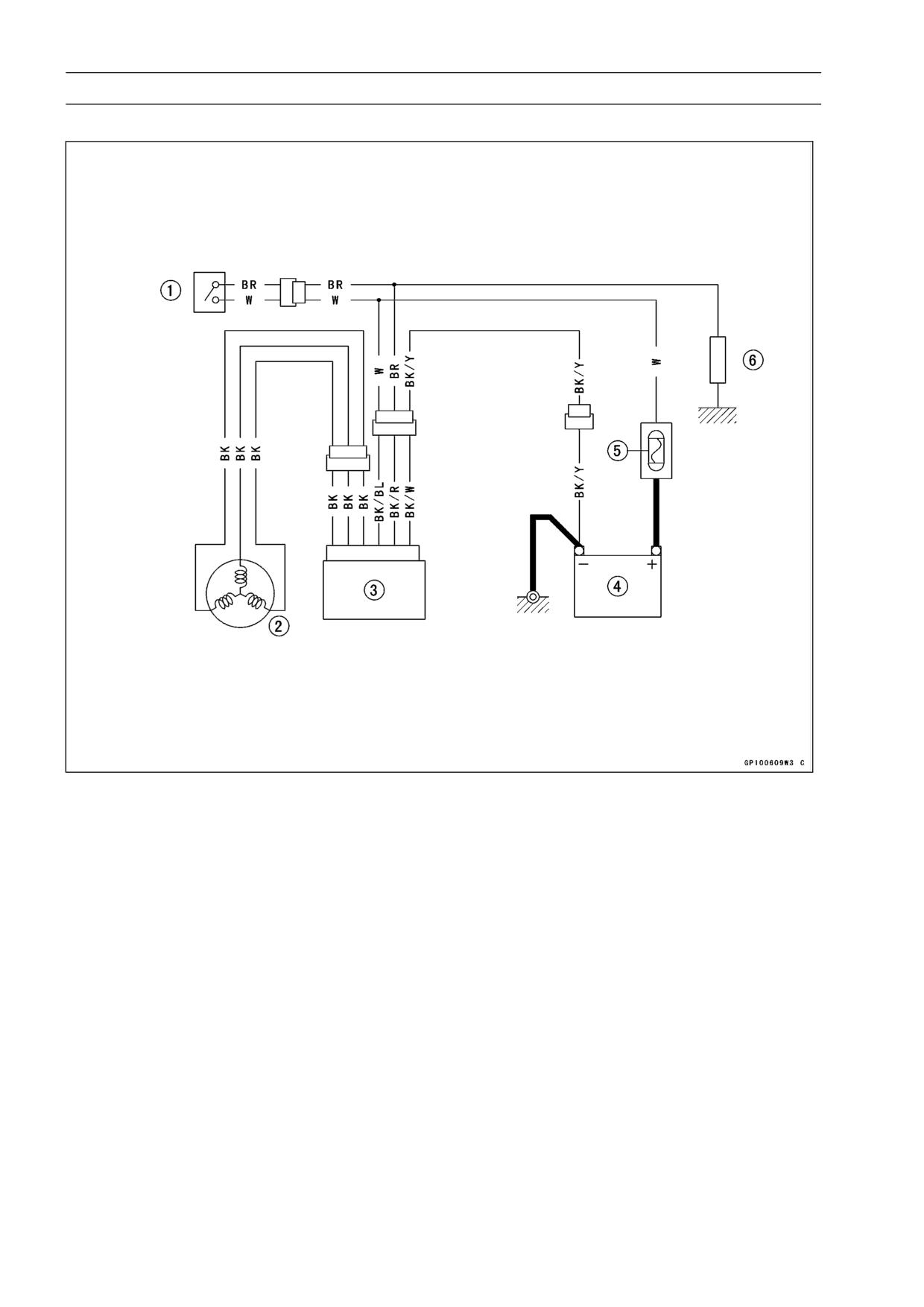
Charging System Circuit
1. Ignition Switch
2. Alternator
3. Regulator/Rectifier
4. Battery
5. Main Fuse 30 A
6. Load
ELECTRICAL SYSTEM 15-35
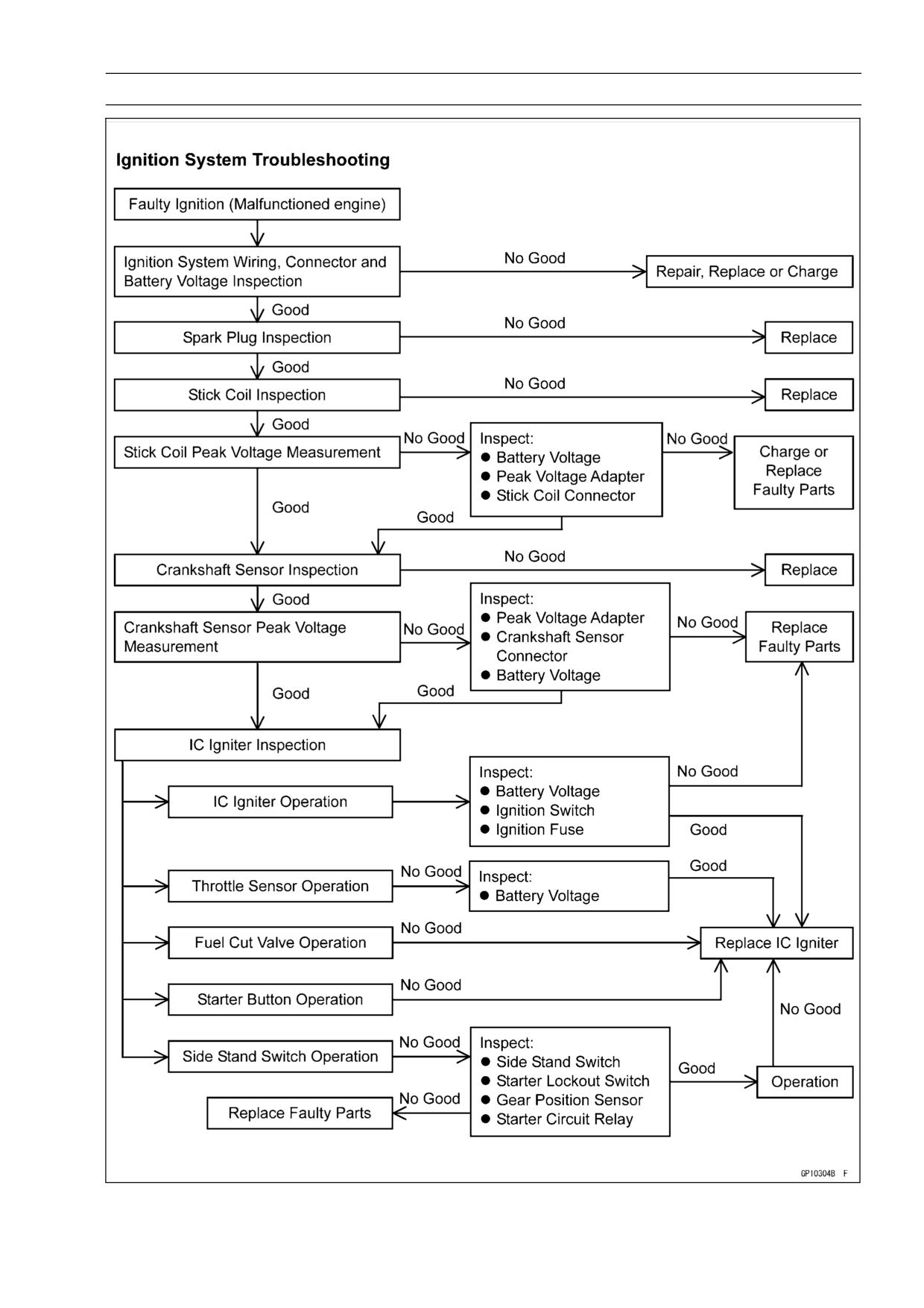
Ignition System
15-36 ELECTRICAL SYSTEM
Ignition System
WARNING
The ignition system produces extremely high volt-
age. Do not touch the spark plugs or stick coils
while the engine is running, or you could receive
a severe electrical shock.
CAUTION
Do not disconnect the battery leads or any other
electrical connections when the ignition switch is
on, or while the engine is running. This is to prevent
IC igniter damage.
Do not install the battery backwards. The negative
side is grounded. This is to prevent damage to the
diodes and IC igniter.
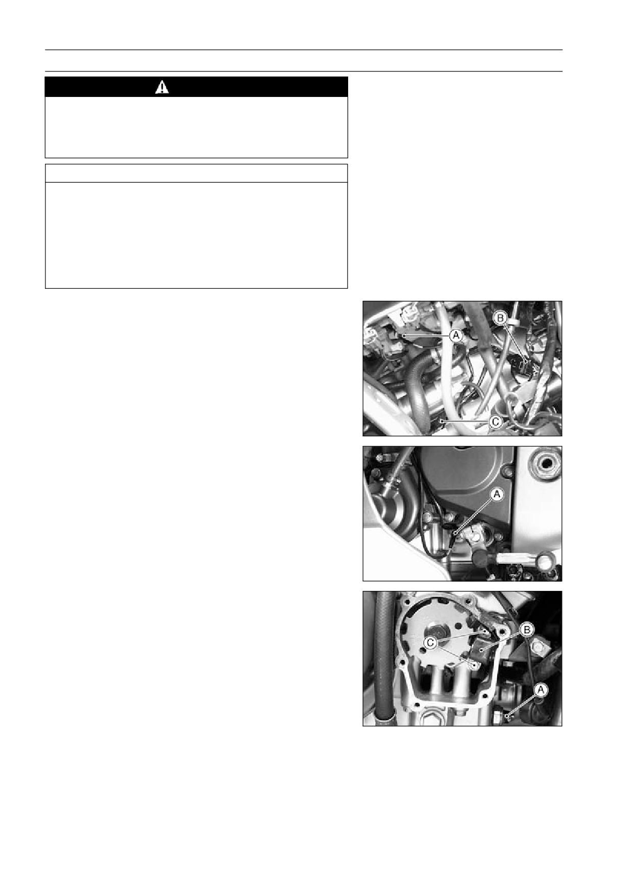
Crankshaft Sensor Removal
Remove:
•
Fuel Tank (see Fuel System chapter)
Right Lower Fairing (see Frame chapter)
Water Temperature Sensor Connector [A]
Crankshaft Sensor Lead Connector [B]
Side Stand Switch Lead Connector [C]
Neutral Switch Lead Connector [A]
Crankshaft Sensor Cover
Oil Pressure Switch Terminal [A]
Remove the crankshaft sensor [B] by taking off the crank-
•
shaft sensor bolts [C].
ELECTRICAL SYSTEM 15-37
Ignition System
Crankshaft Sensor Installation
Route the crankshaft sensor lead correctly (see Cable,
•
Wire, and Hose Routing in General/Information chapter).
Tighten:
•
Torque - Crankshaft Sensor Bolts: 5.9 N·m (0.60 kgf·m, 52
in·lb)
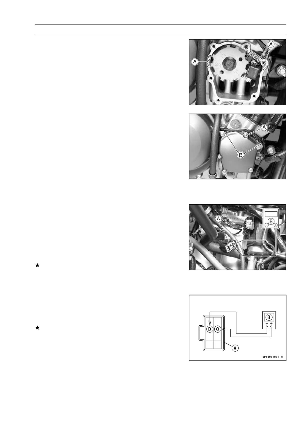
Apply silicone sealant [A] to the crankshaft sensor lead
•
grommet and crankcase halves mating surface on the
front and rear sides of the crankshaft sensor cover mount.
Sealant - Kawasaki Bond (Silicone Sealant): 56019-120
Apply a non-permanent locking agent to the threads of
•
the crankshaft sensor cover bolt [A].
Install the clamps [B] and tighten the crankshaft sensor
•
cover bolts.
Torque - Crankshaft Sensor Cover Bolts: 11 N·m (1.1 kgf·m,
95 in·lb)
Install the oil pressure switch terminal and tighten the ter-
•
minal bolt.
Torque - Oil Pressure Switch Terminal Bolt: 1.5 N·m (0.15
kgf·m, 13 in·lb)
Apply grease to the terminal.
•
Install the other remove parts.
•
Crankshaft Sensor Inspection
Remove:
•
Fuel Tank (see Fuel System chapter)
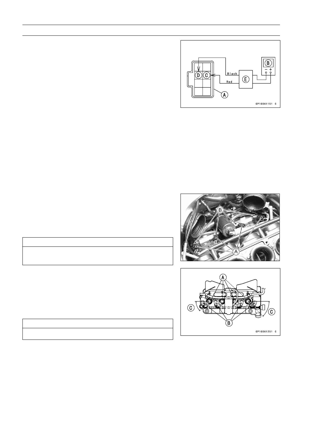
Crankshaft Sensor Lead Connector [A]
Set the hand tester [B] to the × 100 Ω range and us-
•
ing auxiliary wire, connect it to the black lead [C] and
black/yellow lead [D] in the connector [A].
Special Tool - Hand Tester: 57001-1394
If there is more resistance than the specified value, the
coil has an open lead and must be replaced. Much less
than this resistance means the coil is shorted, and must
be replaced.
Crankshaft Sensor Resistance: 452 ∼ 462 Ω
Using the highest resistance range of the tester, measure
•
the resistance between the crankshaft sensor leads and
chassis ground.
Any tester reading less than infinity (∞) indicates a short,
it is necessary to replace the crankshaft sensor assembly.
15-38 ELECTRICAL SYSTEM
Ignition System
Crankshaft Sensor Peak Voltage Measurement
Remove:
•
Fuel Tank (see Fuel System chapter)
Crankshaft Sensor Lead Connector
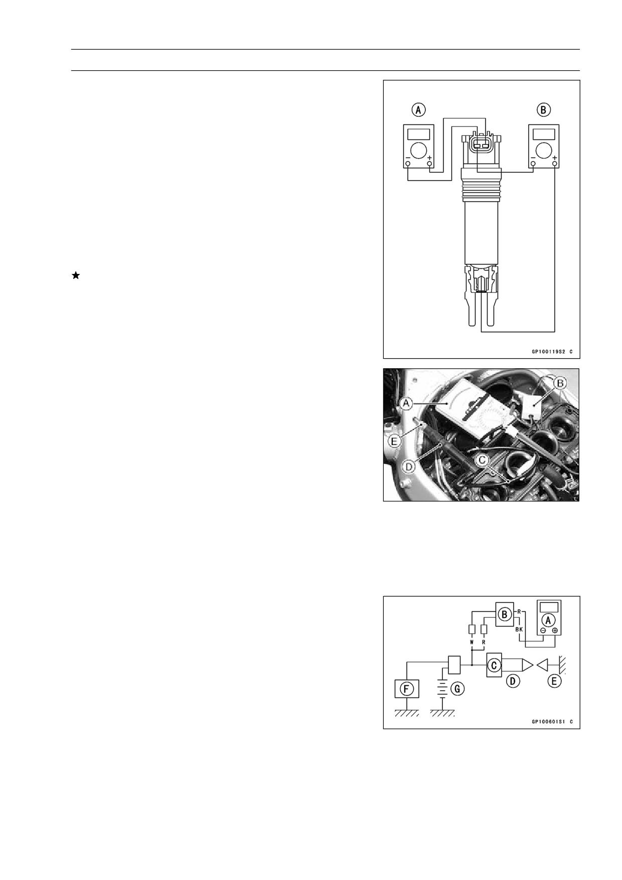
Set the Hand Tester [B] to the × 25 V DC range, and
•
connect it to the peak voltage adapter [E] as shown in
the diagram.
Using two auxiliary wires, connect the black lead (-) of the
•
adapter to black/yellow lead [D] and red lead (+) to black
lead [C] in the crankshaft sensor connection [A].
Turn the ignition switch and engine stop switch on.
•
Grasp the clutch lever and pushing the starter button, turn
•
the engine 4 ∼ 5 seconds with the transmission gear in
neutral to measure the crankshaft sensor peak voltage.
Repeat the measurement 5 or more times.
•
Crankshaft Sensor Peak Voltage
Standard:
3.8 V or more
Special Tool - Hand Tester: 57001-1394
Peak Voltage Adapter: 57001-1415
Type: KEK-54-9-B
Stick Coil (Ignition Coil together with Spark Plug Cap)
Removal
Remove the air cleaner housing (see Fuel System chap-
•
ter).
Disconnect the stick coil connectors [A].
•
Pull the stick coils [B] off the spark plugs.
•
CAUTION
Do not pry the connector part of the coil while re-
moving the coil.
Stick Coil (Ignition Coil together with Spark Plug Cap)
Installation
Install the coil using the following steps.
•
○Insert the coil as shown being careful of the coil head [A]
direction.
○Connect the connectors [B].
○Stick coil connectors angle [C]: about 45°
CAUTION
Do not tap the coil head while installing the coil.
ELECTRICAL SYSTEM 15-39
Ignition System
Stick Coil (Ignition Coil together with Spark Plug Cap)
Inspection
Remove the stick coils (see this chapter).
•
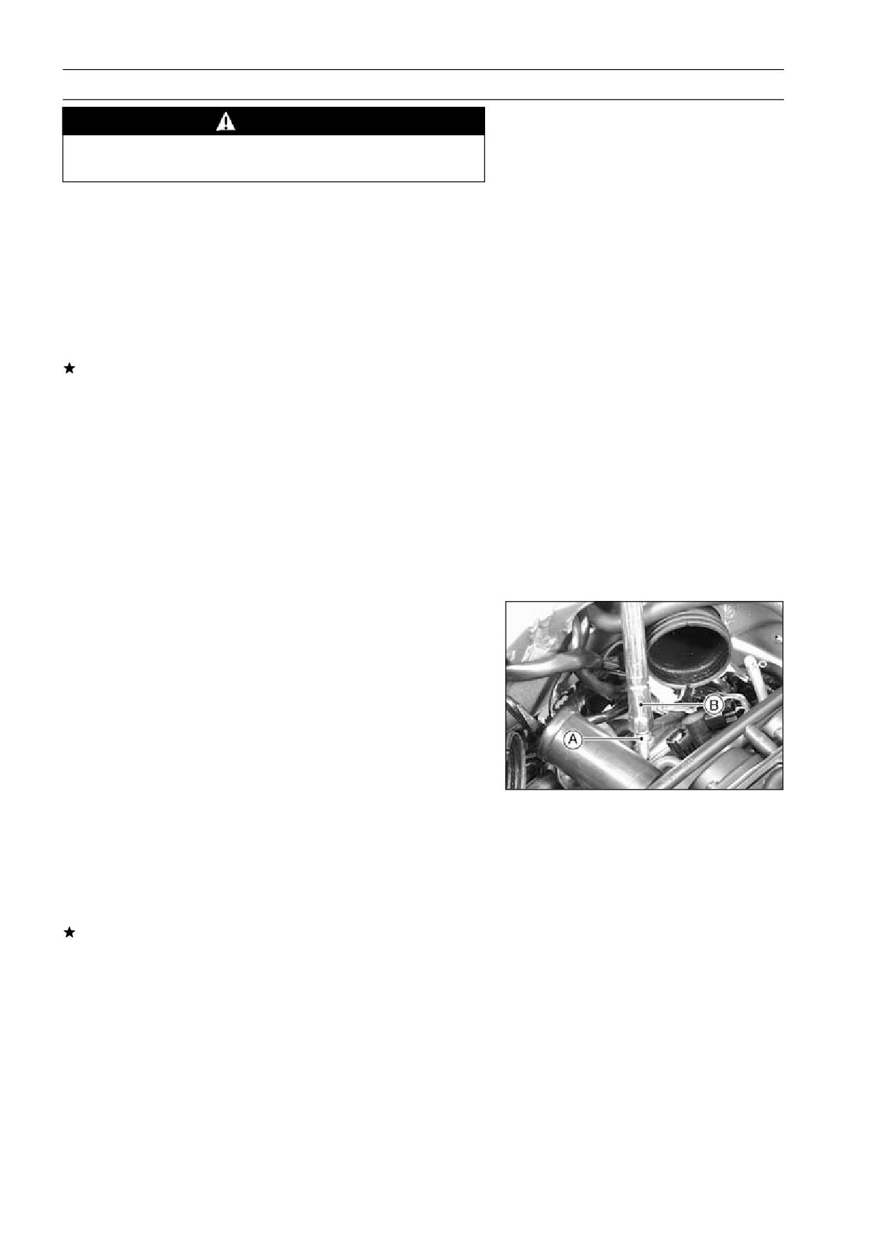
Measure the primary winding resistance [A] as follows.
•
○Connect the hand tester between the coil terminals.
○Set the tester to the × 1 Ω range, and read the tester.
Measure the secondary winding resistance [B] as follows.
•
○Connect the tester between the plug terminal and (-) coil
terminal.
○Set the tester to the × 1 kΩ range and read the tester.
Ignition Coil Winding Resistance
Primary Windings:
1.2 ∼ 1.6 Ω
Secondary Windings:
8.5 ∼ 11.5 kΩ
If the tester does not read as specified, replace the coil.
Stick Coil Primary Peak Voltage Measurement
NOTE
○Be sure the battery is fully charged.
Remove the stick coils (see this chapter), but do not re-
•
move the spark plugs.
Measure the primary peak voltage as follows.
•
○Install the new spark plug [E] into each stick coil [D], and
ground them onto the engine.
○Connect the peak voltage adapter [B] into the hand tester
[A] which is set to the × 250 V DC range.
○Connect the adapter to the lead wire-peak voltage
adapter [C] which is connected between the stick coil
connector and stick coil.
F: IC igniter
G: Battery
Special Tools - Hand Tester: 57001-1394
Lead Wire - Peak Voltage Adapter:
57001
-1449
Peak Voltage Adapter: 57001-1415
Type: KEK-54-9-B
Primary Lead Connection
Adapter (R, +) to lead wire-peak voltage adapter (W)
Adapter (BK, -) to lead wire-peak voltage adapter (R)
15-40 ELECTRICAL SYSTEM
Ignition System
WARNING
To avoid extremely high voltage shocks, do not
touch the spark plugs or tester connections.
Turn the ignition switch and the engine stop switch ON.
•
Pushing the starter button, turn the engine 4 ∼ 5 seconds
•
with the transmission in neutral to measure the primary
peak voltage.
Repeat the measurements 5 times for one stick coil.
•
Stick Coil Primary Peak Voltage
Standard:
92 V or more
Repeat the test for the other stick coil.
•
If the reading is less than the specified value, check the
following.
Stick Coils (see Stick Coil Inspection)
Crankshaft Sensor (see Crankshaft Sensor Inspection)
IC Igniter (see IC Igniter Inspection)
Spark Plug Removal
Remove:
•
Air Cleaner Housing (see Fuel System chapter)
Stick Coils
Remove the spark plugs using the 16 mm plug wrench.
•
Owner’s Tool - Spark Plug Wrench, 16 mm: 92110-1146
Spark Plug Installation
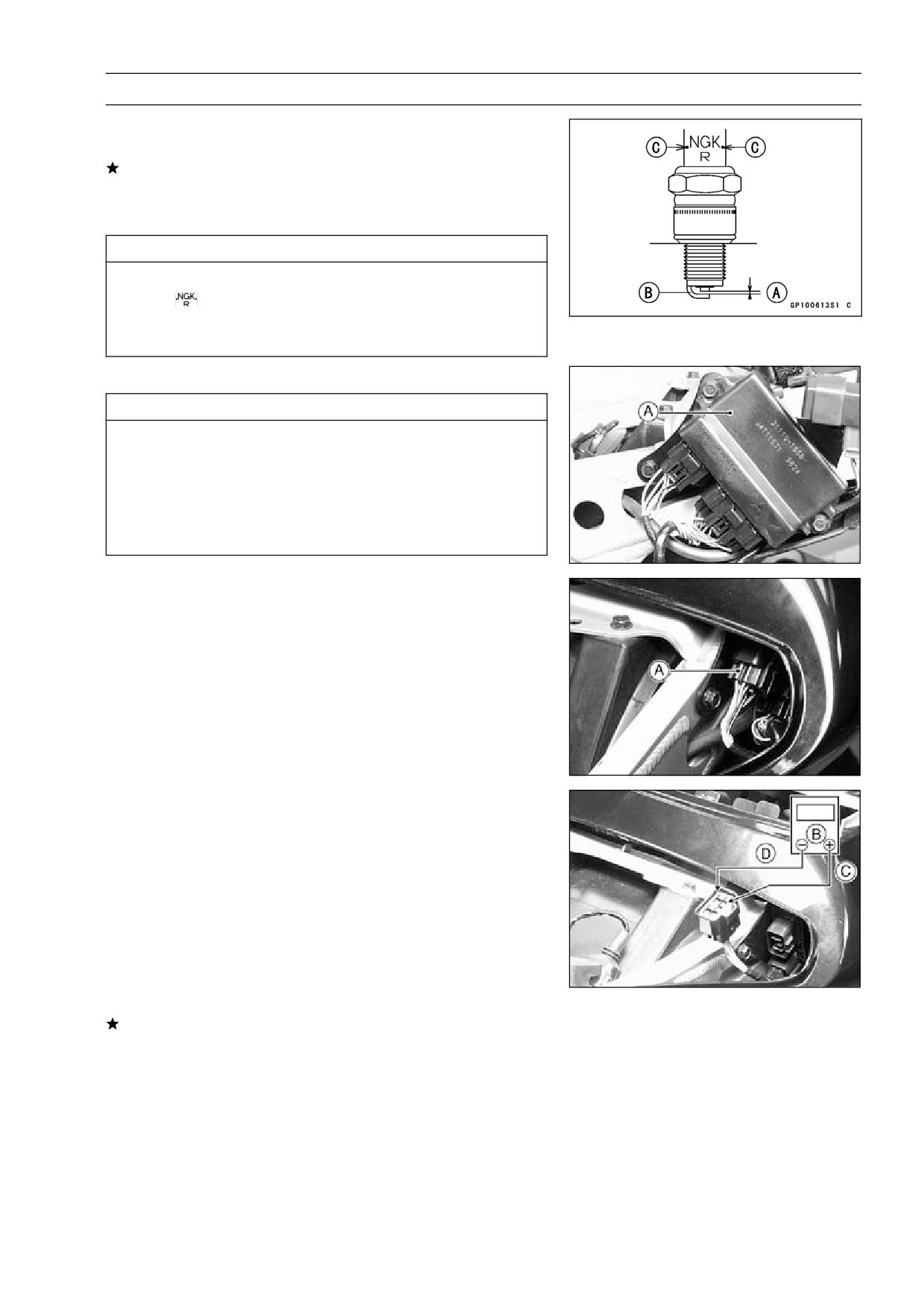
Insert the spark plug vertically into the plug hole with the
•
plug [A] installed in the plug wrench [B].
Owner’s Tool - Spark Plug Wrench, 16 mm: 92110-1146
Tighten:
•
Torque - Spark Plugs: 13 N·m (1.3 kgf·m, 113 in·lb)
Fit the stick coils securely.
•
Spark Plug Cleaning and Inspection
Remove the spark plug, and visually inspect.
•
Clean the spark plug, preferably in a sandblasting device,
•
and then clean off any abrasive particles. The plug may
also be cleaned using a high flash-point solvent and a wire
brush or other suitable tool.
If the spark plug electrodes are corroded or damaged,
or if the insulator is cracked, replace the plug. Use the
standard spark plug or its equivalent.
ELECTRICAL SYSTEM 15-41
Ignition System
Spark Plug Gap Inspection
Measure the gap [A] with a wire-type thickness gauge.
•
If the gap is incorrect, carefully bend the side electrode
[B] with a suitable tool to obtain the correct gap.
Spark Plug Gap: 0.7 ∼ 0.8 mm (0.028 ∼ 0.031 in.)
CAUTION
Use only the recommended spark plugs (special
marks
). These spark plugs have special marks
[C] on the insulator, as shown. Other spark plugs
will wear prematurely.
IC Igniter Inspection
CAUTION
When inspecting the IC igniter [A], observe the fol-
lowing to avoid damage to the IC Igniter.
Do not disconnect the IC igniter with the ignition
switch on. This may damage the IC igniter.
Do not disconnect the battery leads while the en-
gine is running. This may damage the IC igniter.
IC Igniter Operation Check
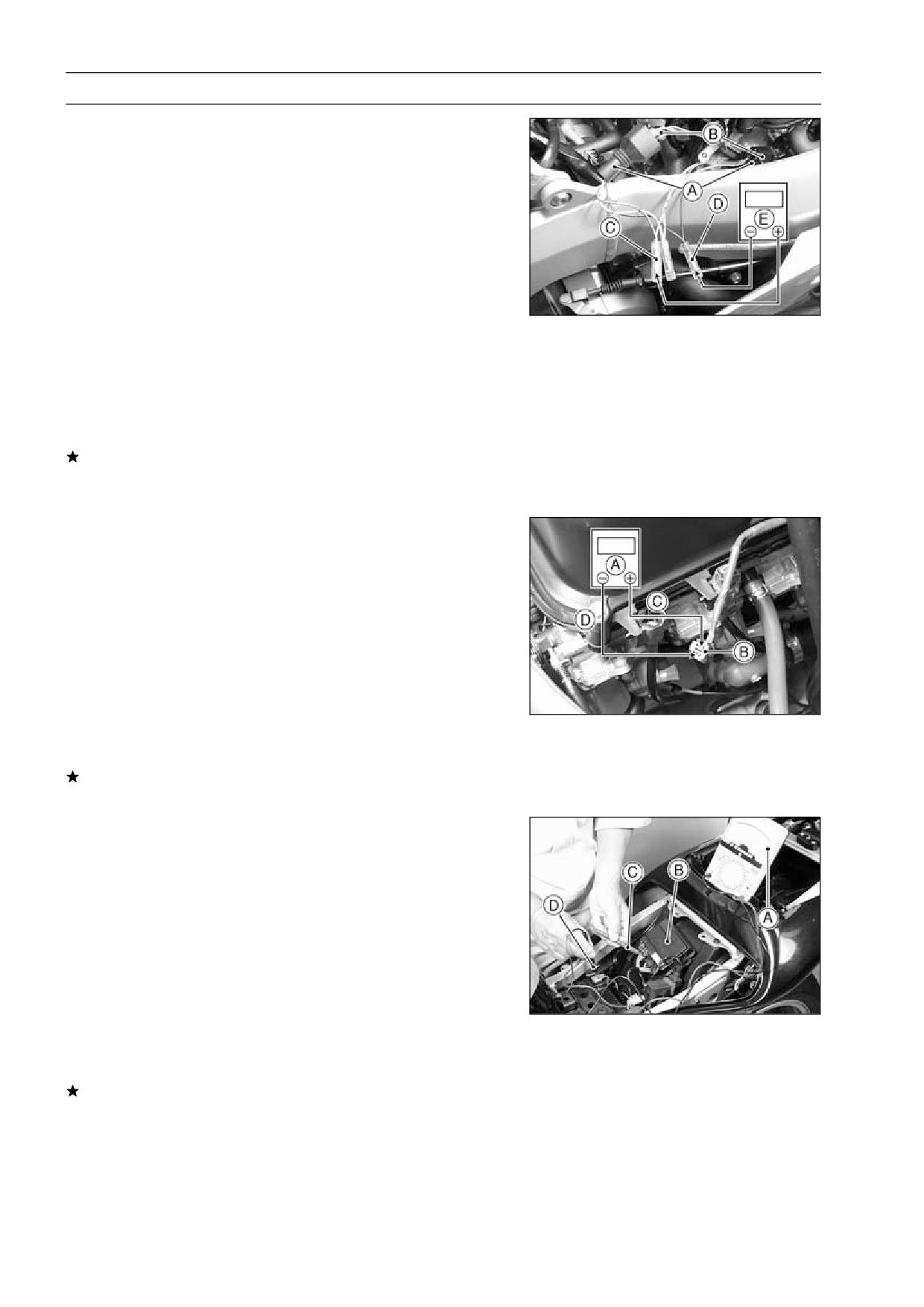
Remove the seats (see Frame chapter).
•
Disconnect the IC igniter left side connector [A].
•
Set the Hand Tester [B] to the × 25 V DC range, and using
•
two auxiliary wires, connect it to the connector come from
harness side as follows.
Tester (+) terminal [C] → BR/W lead
Tester (-) terminal [D] → BK/Y lead
Special Tools - Hand Tester: 57001-1394
Needle Adapter Set: 57001-1457
Turn the ignition switch on , and read the voltage.
•
IC Igniter Operation Voltage: Battery Voltage
If the tester reading is not specified one, check the battery
voltage, ignition switch and ignition fuse.
15-42 ELECTRICAL SYSTEM
Ignition System
Throttle Sensor Operation Check
Remove the fuel tank (see fuel System chapter).
•
Disconnect the throttle sensor lead connector.
•
Connect the adapter [A] between the connectors [B].
•
Special Tool - Throttle Sensor Setting Adapter:
57001
-1521
Set the Hand Tester [E] to the × 10 V DC range, and
•
connect it to the adapter as follows.
Hand Tester (+) Terminal → BL Lead [C]
Hand Tester (-) Terminal → BK/BL Lead [D]
Special Tools - Hand Tester: 57001-1394
Needle Adapter Set: 57001-1457
Turn the ignition switch on, and read the voltage.
•
Throttle Sensor Voltage: approx. 5 V
If the voltage is out of specified one extremely, check the
Battery Voltage. If the Battery Voltage is correct, replace
the IC igniter.
Fuel Cut Valve Operation Check
Remove the fuel tank (see Fuel System chapter).
•
Set the Hand Tester [A] to the × 25 V DC range, and con-
•
nect it to the each fuel cut valve connector [B] as follows.
Hand Tester (+) Terminal [C] → BR/BK Lead
Hand Tester (-) Terminal [D] → R or O/G or O/BK or
LG/BK Lead
Special Tool - Hand Tester: 57001-1394
Remove the each ignition coil at each valve test.
•
Turn the ignition switch on, and push the starter button.
•
Read the voltage at the moment.
•
If the tester reading is approximately battery voltage, it is
correct. If the voltage is not read, replace the IC igniter.
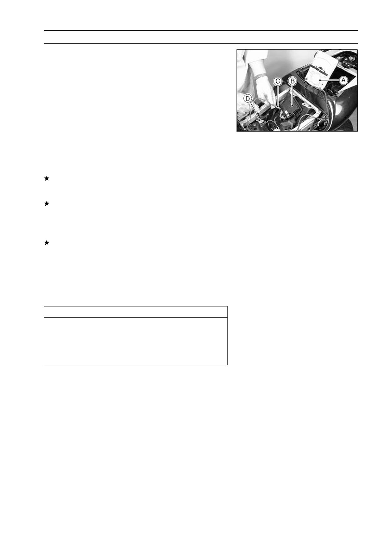
Starter Button Operation Check
Remove the seats (see Frame chapter).
•
Set the Hand Tester [A] to the × 10 V DC range, connect
•
it to the junction box [B] lead as follows.
Hand Tester (+) Terminal [C]
→ BK/R Lead
Hand Tester (-) Terminal [D]
→ Frame Ground
Special Tools - Hand Tester: 57001-1394
Needle Adapter Set: 57001-1457
Turn the ignition switch on and push the starter button.
•
Read the voltage.
•
Starter Button Voltage: 8 V or more
If the tester reading is not specified one, replace the IC
igniter.
ELECTRICAL SYSTEM 15-43
Ignition System
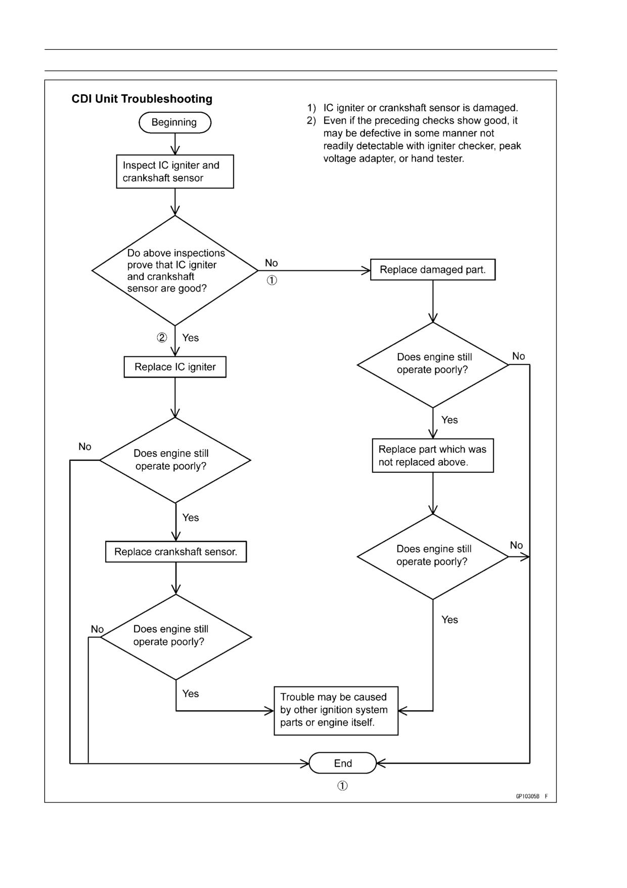
Side Stand Switch Operation Check
Remove the seats (see Frame chapter).
•
Change the transmission gear to the first position and set
•
the side stand to “ON” position.
Set the Hand Tester [A] to the × 25 V DC range, and
•
connect it to the junction box [B] lead as follows.
Hand Tester (+) Terminal [C]
→ G/BK Lead
Hand Tester (-) Terminal [D]
→ Frame Ground
Special Tools - Hand Tester: 57001-1394
Needle Adapter Set: 57001-1457
Turn the ignition switch on and push the starter button.
•
Read the voltage.
•
Side Stand Switch Operation Voltage: 6 ∼ 13.4 V
If the tester reading is not specified one, check the side
stand switch, starter lock out switch, gear position sensor
and starter circuit relay.
If the tester reading is correct, check the following.
Grasp the clutch lever, and start the engine.
•
○Side stand - “ON” position, transmission gear-first position
Release the clutch lever slowly.
•
If the engine does not stop after releasing the clutch lever
fully, the IC igniter is defective.
NOTE
○Some inspections as to the IC igniter are operated, but
the cause of troubles may be not able to clear enoughly.
If the cause of troubles are not cleared in described
inspections, replace the IC igniter with a new one.
CAUTION
Use only Hand Tester 57001-1394 for this test. A
tester other than the Kawasaki Hand Tester may
show different readings.
If a megger or a meter with a large-capacity battery
is used, the IC igniter will be damaged.
15-44 ELECTRICAL SYSTEM
Ignition System
ELECTRICAL SYSTEM 15-45
Ignition System
Ignition System Circuit
1. Junction Box
9. Main Fuse 30 A
2. Ignition Switch
10. Starter Lockout Switch
3. Engine Stop Switch
11. Battery
4. Starter Button
12. Neutral Switch
5. Throttle Sensor
13. Side Stand Switch
6. Spark Plugs
14. Crankshaft Sensor
7. Ignition Coils (Stick Coils)
15. IC Igniter
8. Ignition Fuse 10 A
A. United States, Canada, Australia and
Malaysia Models
15-46 ELECTRICAL SYSTEM
Electric Starter System
Starter Motor Removal
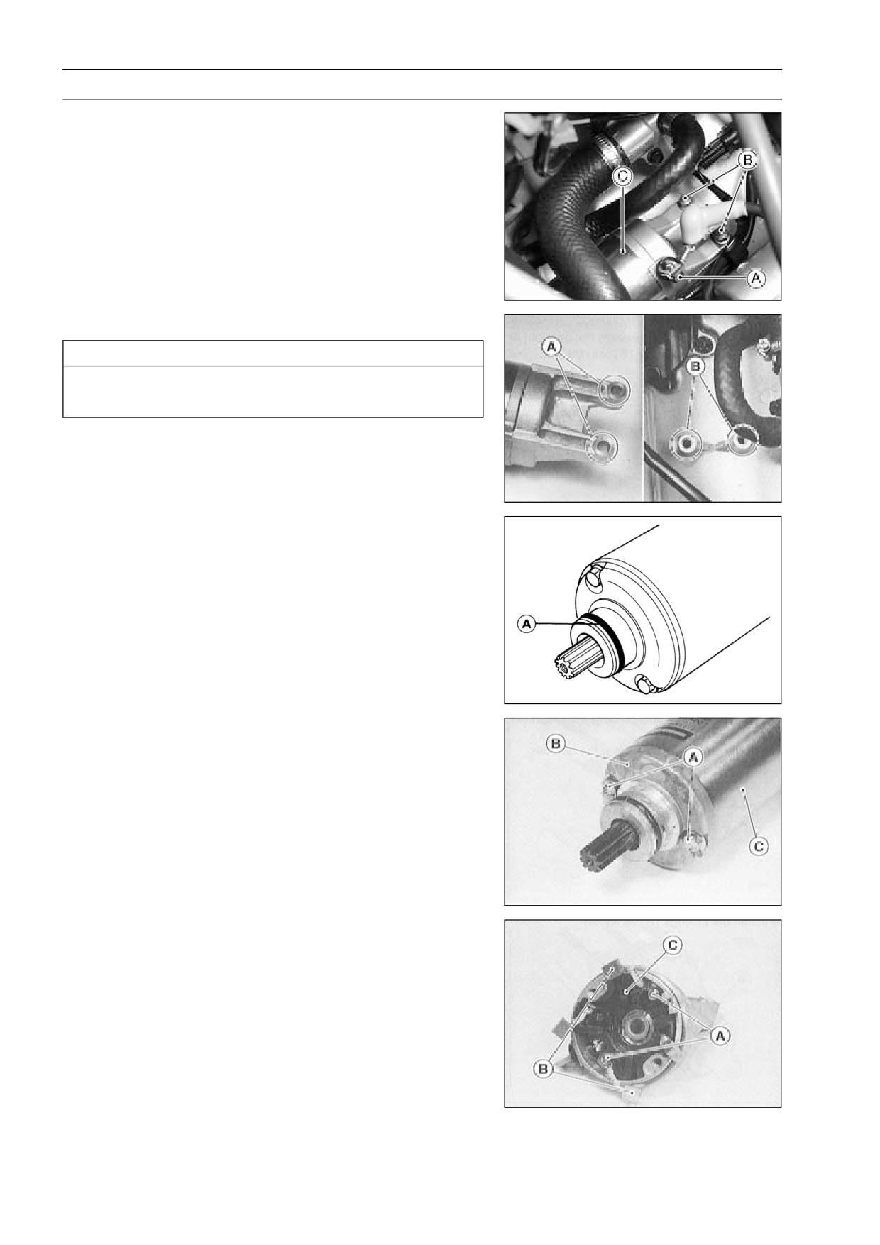
Remove the fuel tank (see Fuel System chapter).
•
Slide back the rubber cap.
•
Remove the starter motor terminal nut [A] and the mount-
•
ing bolts [B].
Pull out the starter motor [C].
•
Starter Motor Installation
CAUTION
Do not tap the starter motor shaft or body. Tapping
the shaft or body could damage the motor.
When installing the starter motor, clean the starter mo-
•
tor legs [A] and crankcase [B] where the starter motor is
grounded.
Replace the O-ring [A] with a new one.
•
Apply grease to the O-ring.
•
Tighten:
•
Torque - Starter Motor Mounting Bolts: 12 N·m (1.2 kgf·m,
104 in·lb)
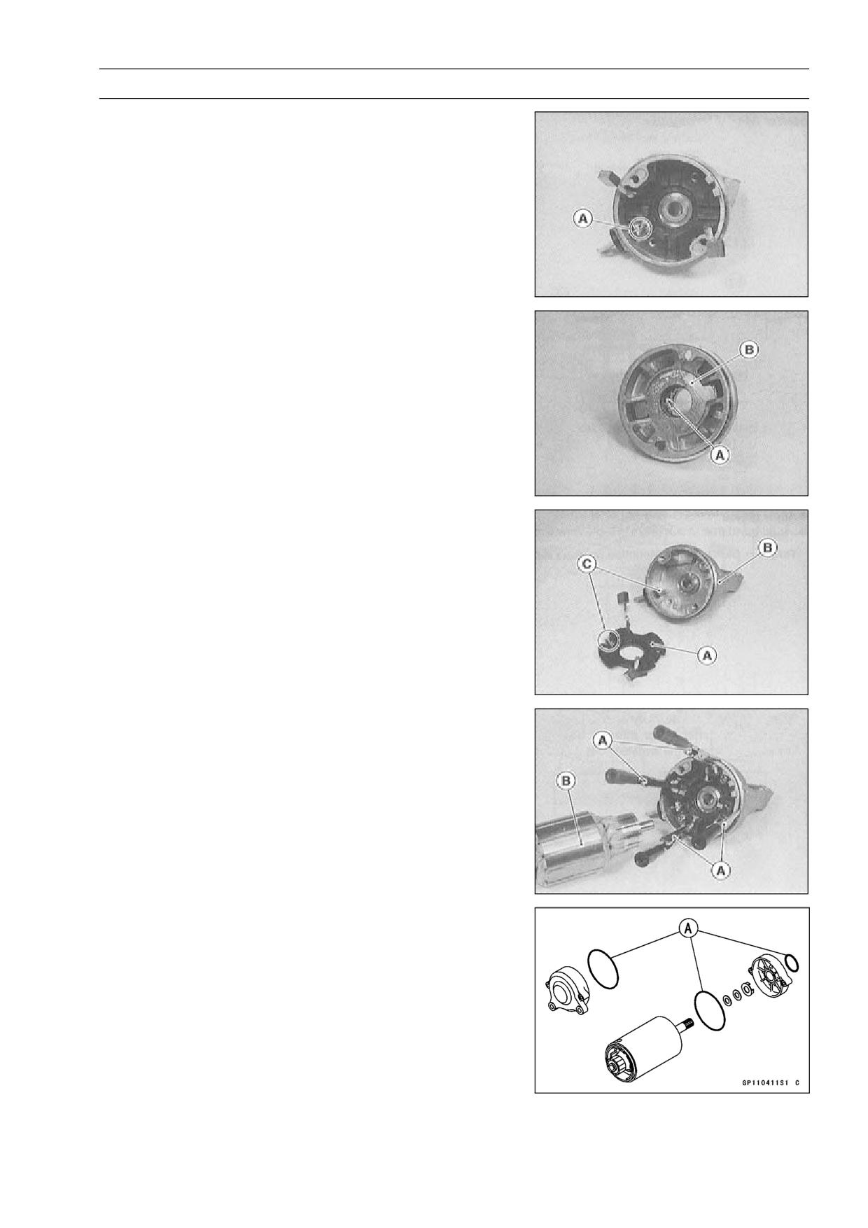
Starter Motor Disassembly
Take off the starter motor through bolts [A] and remove
•
both end covers [B] and pull the armature out of the yoke
[C].
Remove:
•
Brush Springs
Brush Holder Plate Screw [A]
Negative Brushes [B]
Brush Holder Plate [C]
ELECTRICAL SYSTEM 15-47
Electric Starter System
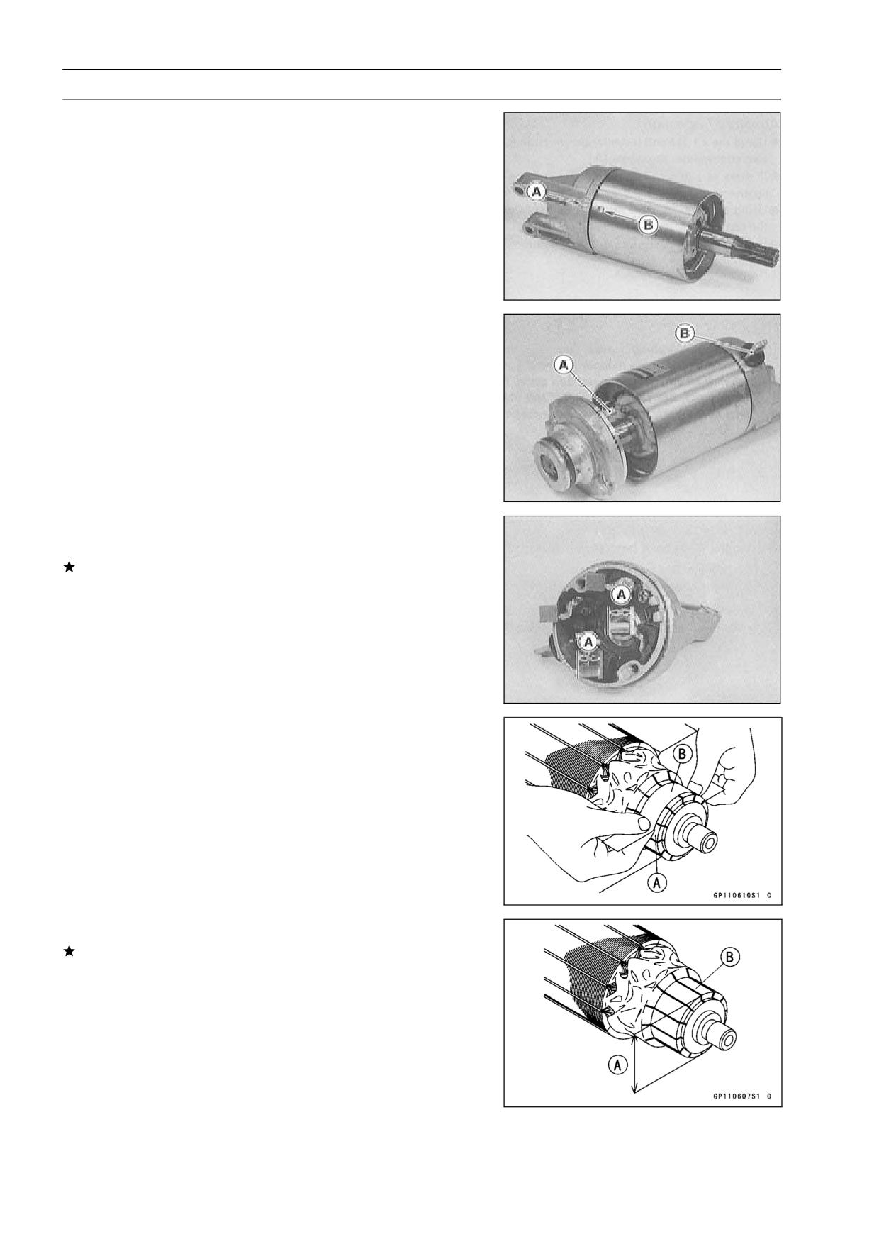
Unsolder the terminal [A] on the positive brush plate and
•
remove it.
Starter Motor Assembly
Apply a thin coat of grease to the oil seal [A].
•
Fit the toothed washer [B] into the left-hand end cover.
•
Install the positive brush plate [A] in the right-hand end
•
cover [B] and solder the terminals [C].
Press the springs and holding the brush leads with suit-
•
able clips [A] as shown.
Put the armature [B] among the brushes.
•
Install the O-rings [A] as shown.
•
15-48 ELECTRICAL SYSTEM
Electric Starter System
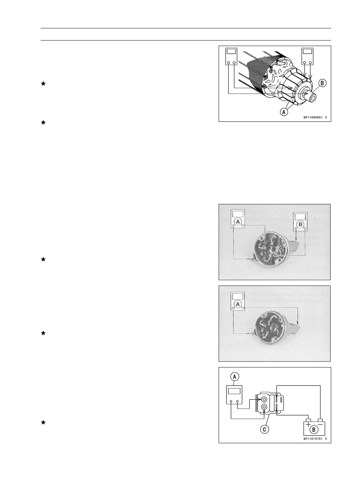
Align the groove [A] in the right-hand end cover and the
•
mark [B] on the yoke.
Align the tongue [A] on the left-hand end cover and the
•
terminal [B] on the right-hand end cover.
Brush Inspection
Measure the length [A] of each brush.
•
If any is worn down to the service limit, replace all
brushes.
Starter Motor Brush Length
Standard:
7 mm (0.28 in.)
Service Limit:
3.5 mm (0.14 in.)
Commutator Cleaning and Inspection
Smooth the commutator surface [A] if necessary with fine
•
emery cloth [B], and clean out the grooves.
Measure the diameter [A] of the commutator [B].
•
If the commutator diameter is less than the service limit,
replace the starter motor with a new one .
Commutator Diameter
Standard:
24 mm (0.94 in.)
Service Limit:
23 mm (0.91 in.)
ELECTRICAL SYSTEM 15-49
Electric Starter System
Armature Inspection
Using the × 1 Ω hand tester range, measure the resis-
•
tance between any two commutator segments [A].
Special Tool - Hand Tester: 57001-1394
If there is a high resistance or no reading (∞) between any
two segments, a winding is open and the starter motor
must be replaced.
Using the highest hand tester range, measure the resis-
•
tance between the segments and the shaft [B].
If there is any reading at all, the armature has a short and
the starter motor must be replaced.
NOTE
○Even if the foregoing checks show the armature to be
good, it may be defective in some manner not readily
detectable with the hand tester. If all other starter motor
and starter motor circuit components check good, but
the starter motor still does not turn over or only turns
over weakly, replace the starter motor with a new one.
Brush Lead Inspection
Using the × 1 Ω hand tester range, measure the resis-
•
tance as shown.
[A] Terminal Bolt and Positive Brush
[B] Right-hand End Cover and Negative Brush
Special Tool - Hand Tester: 57001-1394
If there is not close to zero ohms, the brush lead has an
open. Replace the positive brush assembly and/or the
negative brush subassembly.
Right-hand End Cover Assembly Inspection
Using the highest hand tester range, measure the resis-
•
tance as shown.
[A] Terminal and Right-hand End Cover
Special Tool - Hand Tester: 57001-1394
If there is any reading, the right-hand end cover assembly
have a short. Replace the right-hand end cover assembly.
Starter Relay Inspection
Remove the seats.
•
Remove the starter relay.
•
Connect the hand tester [A] and 12 V battery [B] to the
•
starter relay [C] as shown.
Special Tool - Hand Tester: 57001-1394
If the relay does not work as specified, the relay is defec-
tive. Replace the relay.
Testing Relay
Tester Range:
× 1 Ω range
Criteria:
When battery is connected → 0 Ω
When battery is disconnected → ∞ Ω
15-50 ELECTRICAL SYSTEM
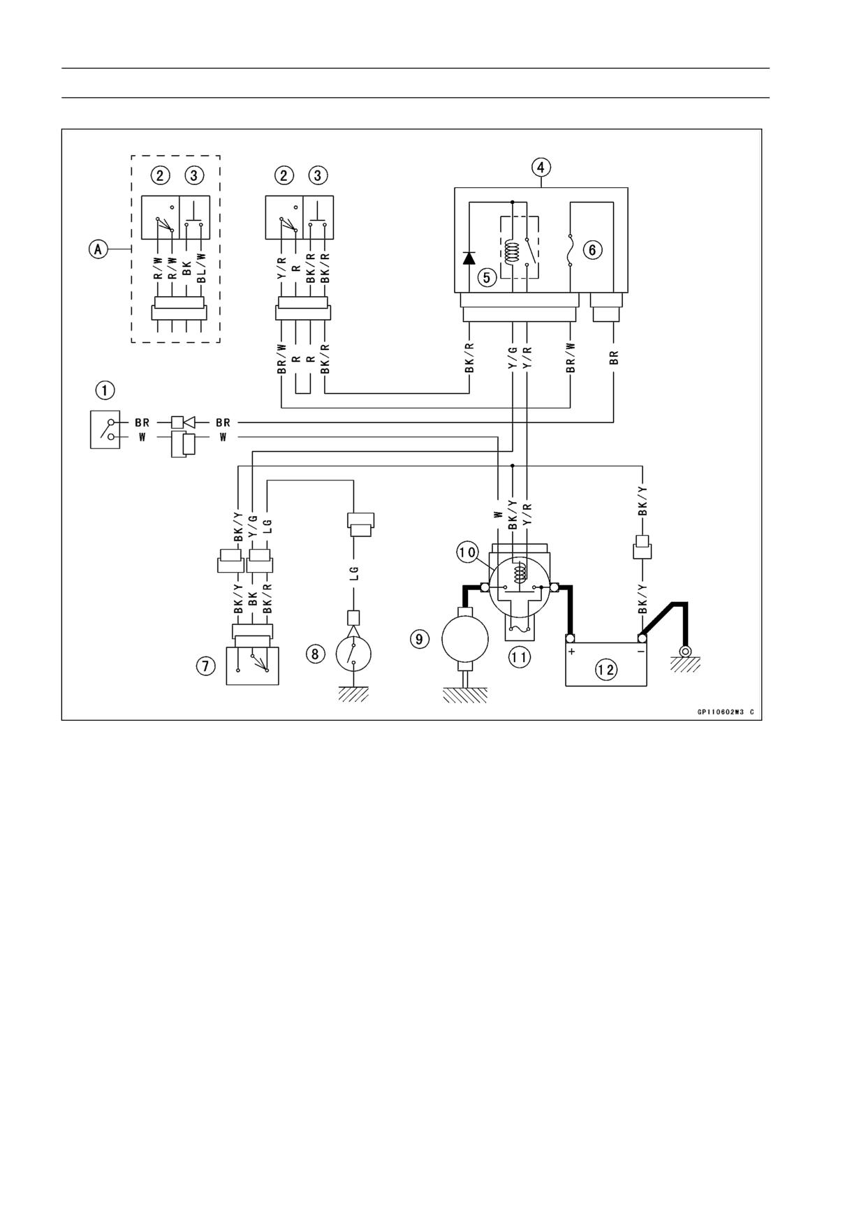
Electric Starter System
Electric Starter Circuit
1. Ignition Switch
2. Engine Stop Switch
3. Starter Button
4. Junction Box
5. Starter Circuit Relay
6. Ignition Fuse 10 A
7. Starter Lockout Switch
8. Neutral Switch
9. Starter Motor
10. Starter Relay
11. Main Fuse 30 A
12. Battery
A. United States, Canada, Australia and Malaysia Models
ELECTRICAL SYSTEM 15-51
Lighting System
The US, Canada, Australia, and Malaysia models adopt
the daylight system and have a headlight relay in the junc-
tion box. In these models, the headlight does not go on
when the ignition switch and the engine stop switch are first
turned on. The headlight comes on after the starter button is
released and stays on until the ignition switch is turned off.
The headlight will go out momentarily whenever the starter
button is pressed and come back on when the button is re-
leased.
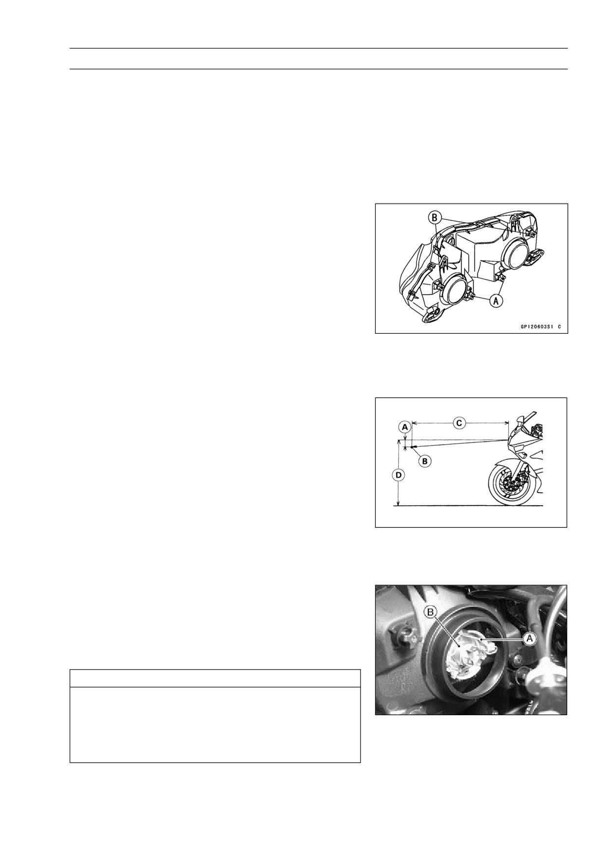
Headlight Beam Horizontal Adjustment
Turn the horizontal adjuster [A] on the headlight in or out
•
until the beam points straight ahead.
Headlight Beam Vertical Adjustment
Turn the vertical adjusters [B] on the headlight in or out to
•
adjust the headlight vertically.
NOTE
○On high beam, the brightest points should be slightly
below horizontal with the motorcycle on its wheels and
the rider seated. Adjust the headlight(s) to the proper
angle according to local regulations.
○For US model, the proper angle is 0.4 degrees below
horizontal. This is 50 mm (2 in) drop at 7.6 m (25 ft)
measured from the center of the headlights with the mo-
torcycle on its wheels and the rider seated.
50 mm (2 in) [A]
Center of Brightest Spot [B]
7.6 m (25 ft) [C]
Height of Headlight Center [D]
Headlight Bulb Replacement
Remove:
•
Headlight Connector
Headlight Bulb Dust Cover
Hook [A]
Headlight Bulb [B]
CAUTION
When handling the quartz-halogen bulb, never
touch the glass portion with bare hands. Always
use a clean cloth. Oil contamination from hands or
dirty rags can reduce bulb life or cause the bulb to
explode.
NOTE
○Clean off any contamination that inadvertently gets on
the bulb with alcohol or soap and water solution.
15-52 ELECTRICAL SYSTEM
Lighting System
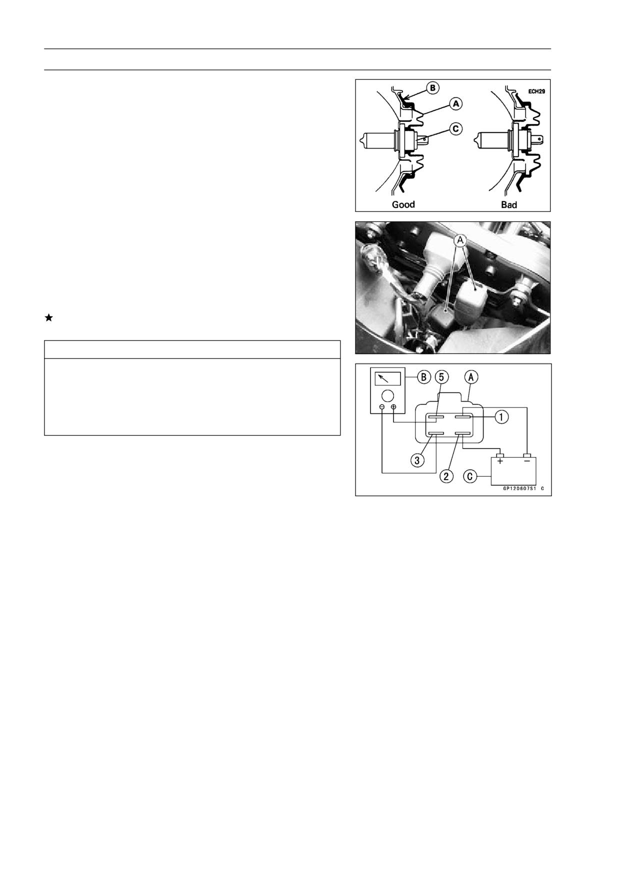
Replace the headlight bulb.
•
Fit the dust cover [A] with the Top mark [B] upward onto
•
the bulb [C] firmly as shown.
After installation, adjust the headlight aim (see this chap-
•
ter).
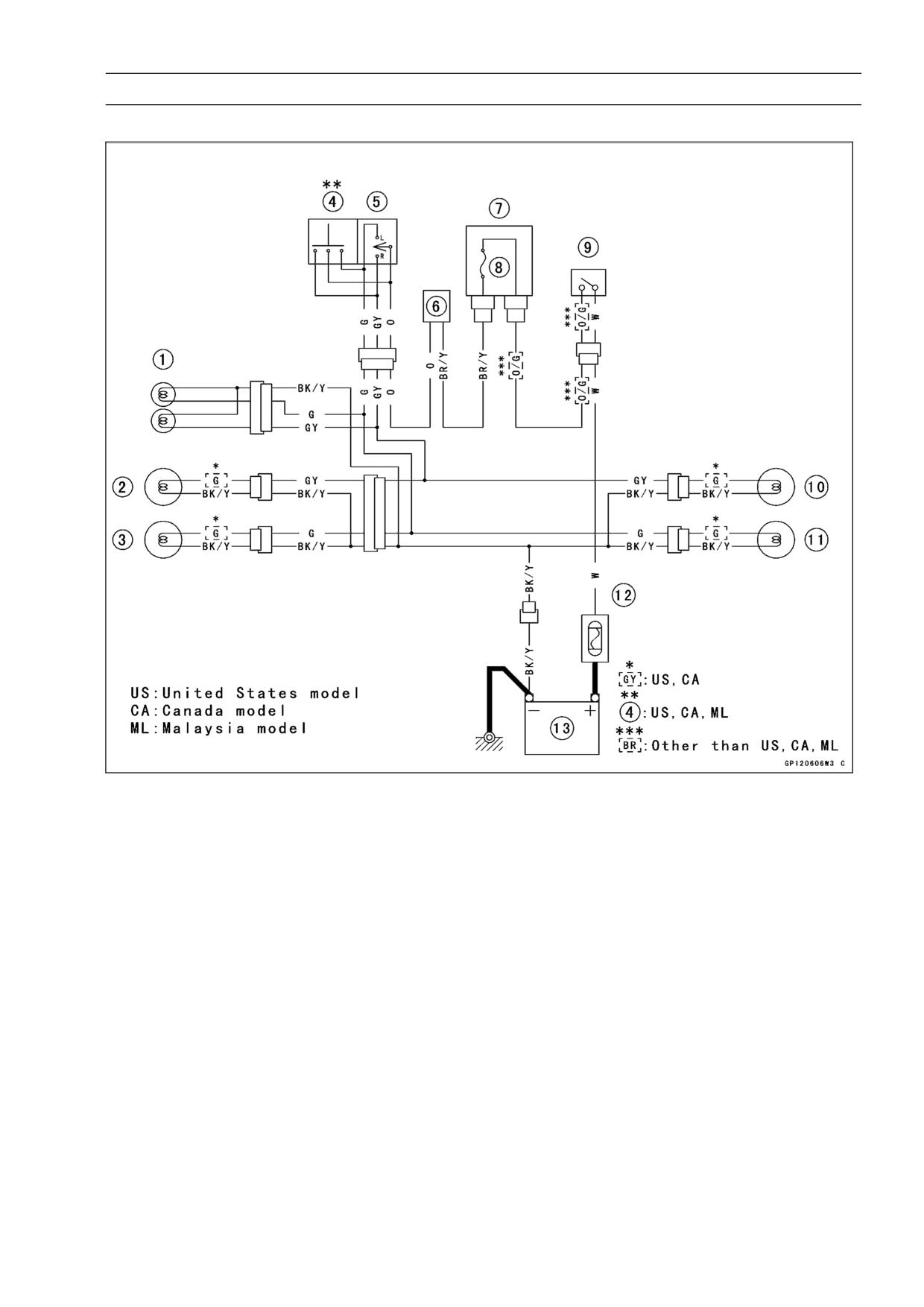
Headlight Relay Unit Inspection
Remove the windshield.
•
Take off the headlight relay units [A].
•
Set the hand tester to the × 1 Ω range and make the
•
measurements shown in the figure.
Special Tool - Hand Tester: 57001-1394 [B]
If the tester readings are not as specified, replace the
headlight relay unit.
CAUTION
Use only Hand Tester 57001-1394 for this test. An
ohmmeter other the Kawasaki Hand Tester may
show different readings.
If a megger or a meter with a large-capacity battery
is used, the headlight relay unit will be damaged.
Testing Relay
Criteria:
When battery is connected → 0Ω
When battery is disconnected → ∞Ω
Headlight Relay [A]
12 V Battery [C]
ELECTRICAL SYSTEM 15-53
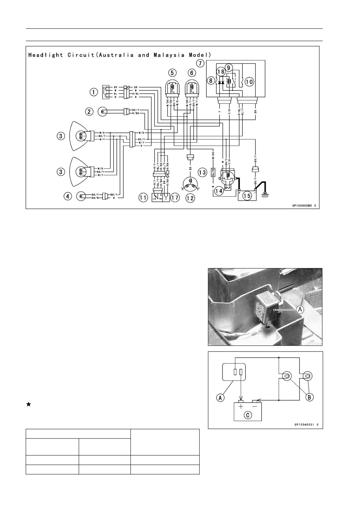
Lighting System
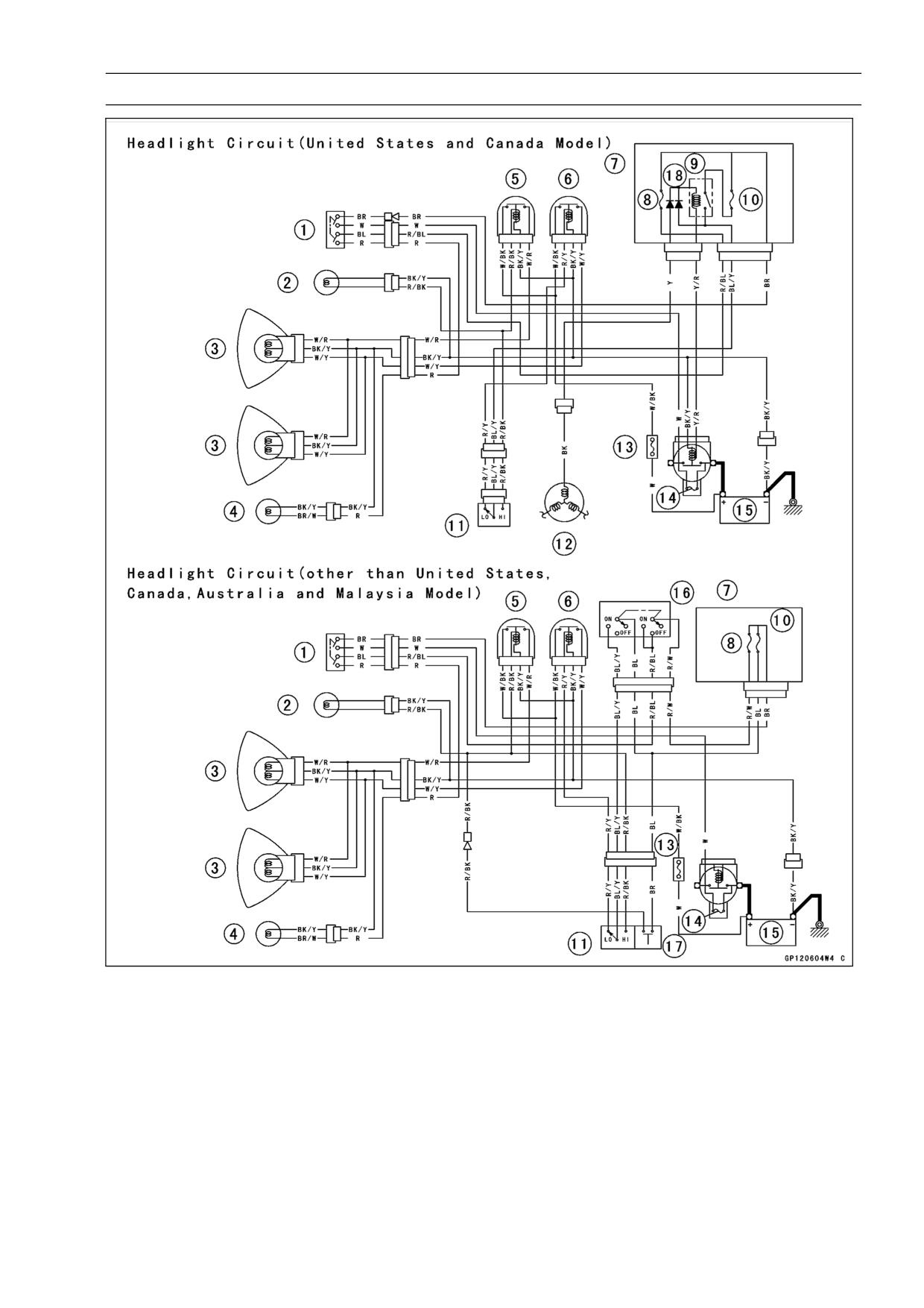
1. Ignition Switch
10. Headlight Fuse 10 A
2. High Beam Indicator Light
11. Dimmer Switch
3. Headlight
12. Alternator
4. City Light
13. Headlight Fuse 20 A
5. Headlight Relay (Hi)
14. Main Fuse 30 A
6. Headlight Relay (Lo)
15. Battery
7. Junction Box
16. Headlight Switch
8. Tail Light Fuse 10 A
17. Passing Button
9. Headlight Circuit Relay
18. Diodes.
15-54 ELECTRICAL SYSTEM
Lighting System
1. Ignition Switch
7. Junction Box
14. Main Fuse 30 A
2. High Beam Indicator
8. Tail Light Fuse 10 A
15. Battery
Light
9. Headlight Circuit Relay
16. Headlight Switch
3. Headlight
10. Headlight Fuse 10 A
17. Passing Button
4. City Light
11. Dimmer Switch
18. Diodes.
5. Headlight Relay (Hi)
12. Alternator
6. Headlight Relay (Lo)
13. Headlight Fuse 20 A
Turn Signal Relay Inspection
Remove:
•
Seats (see Frame chapter)
Turn Signal Relay [A]
Connect one 12 V battery and turn signal lights as indi-
•
cated in the figure, and count how may times the lights
flash for one minute.
Turn Signal Relay [A]
Turn Signal Lights [B]
12 V Battery [C]
If the lights do not flash as specified, replace the turn sig-
nal relay.
Testing Turn Signal Relay
Load
The Number of
Flashing times (c/m*)
Wattage (W)
Turn Signal Lights
1**
21 or 23
140 - 250
2
42 or 46
75-95
(*): Cycle(s) per minute
(**): Correspond to “one light burned out”
ELECTRICAL SYSTEM 15-55
Lighting System
Turn Signal Light Circuit
1. Turn Signal Indicator Lights (Right & Left)
2. Front Right Turn Signal Light
3. Front Left Turn Signal Light
4. Hazard Button
5. Turn Signal Switch
6. Turn Signal Relay
7. Junction Box
8. Turn Signal Relay Fuse 10 A
9. Ignition Switch
10. Rear Right Turn Signal Light
11. Rear Left Turn Signal Light
12. Main Fuse 30 A
13. Battery
15-56 ELECTRICAL SYSTEM
Fuel Pump
The fuel pump [A] operates when the starter button is
pushed on or the engine is running.
When the fuel level in the float chamber is low, the fuel
pump operates to supply the fuel into the float chamber.
When the fuel reaches a certain level, the fuel pressure
rises, and the fuel pump stops.
Fuel Pump Removal/Installation
Refer to the Fuel System chapter.
•
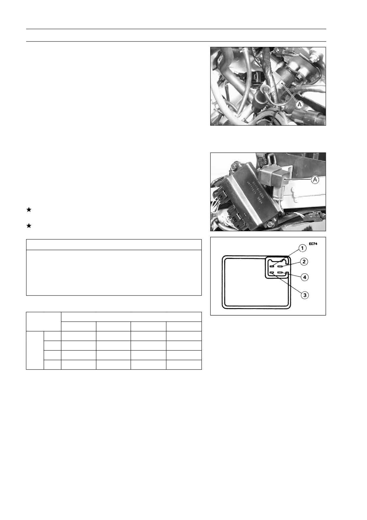
Fuel Pump Relay Internal Resistance Inspection
Remove the seats (see Frame chapter).
•
Take off the fuel pump relay [A].
•
Set the hand tester to the × 1 kΩ range and make the
•
measurements shown in the table.
Special Tool - Hand Tester: 57001-1394
If the tester readings are not as specified, replace the fuel
pump relay.
If the tester readings are normal, check the fuel pump
operation.
CAUTION
Use only Hand Tester 57001-1394 for this test. An
ohmmeter other than the Kawasaki Hand Tester
may show different readings.
If a megger or a meter with a large-capacity battery
is used, the pump relay will be damaged.
Fuel Pump Relay Internal Resistance
Range ×
Tester (+) Lead Connection
1 kΩ
1
2
3
4
1
-
∞
∞
∞
2
∞
-
∞
∞
*(-)
3
∞
10 ∼ 100
-
∞
4
∞
20 ∼ 200
1 ∼ 5
-
(-)*: Tester (-) Lead Connection
ELECTRICAL SYSTEM 15-57
Fuel Pump
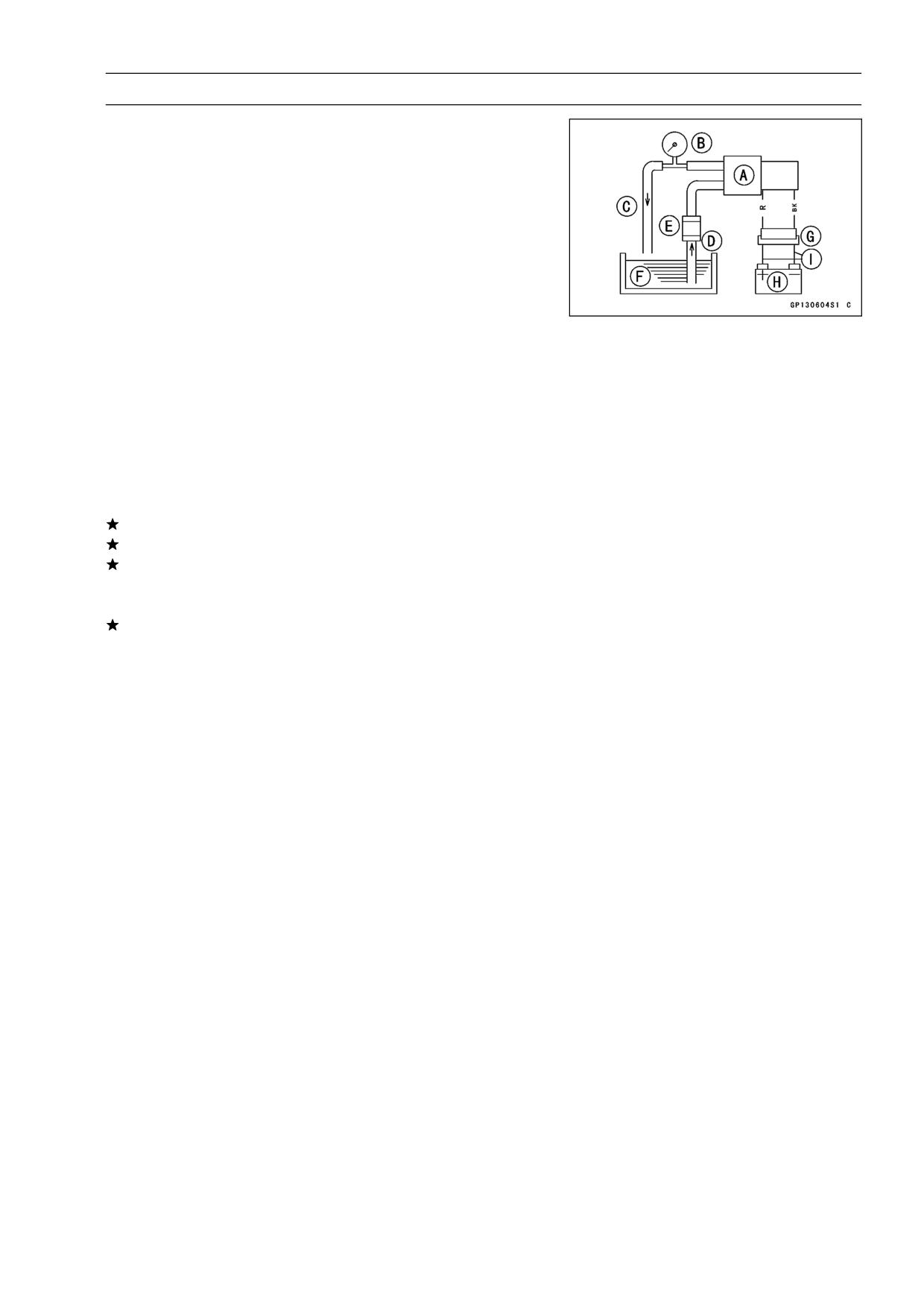
Fuel Pump Operational Inspection
Remove the fuel pump with the fuel filter (see Fuel System
•
chapter).
Prepare a container filled with kerosene.
•
Prepare the rubber hoses, and connect them to the pump
•
fittings.
Connect a suitable pressure gauge to the outlet hose as
•
shown.
Fuel Pump [A]
Pressure Gauge [B]
Outlet Hose [C]
Inlet Hose [D]
Fuel Filter [E]
Kerosene [F]
2-Pin Connector [G]
Battery [H]
Auxiliary Leads [I]
Connect the pump leads to the battery using auxiliary
•
wires as shown.
If the pump operates, check the pump relay.
If the pump does not operate, the pump is defective.
If the pump operates and the pump relay is normal, close
the outlet hose while operating the fuel pump.
When the pump stops, read the pressure gauge.
•
If the pressure gauge reading is out of the specified pres-
sure, the pump is defective.
Fuel Pump Pressure
Standard:
11 ∼ 16 kPa (0.11 ∼ 0.16 kgf/cm², 1.6 ∼ 2.3
psi)
15-58 ELECTRICAL SYSTEM
Fuel Pump
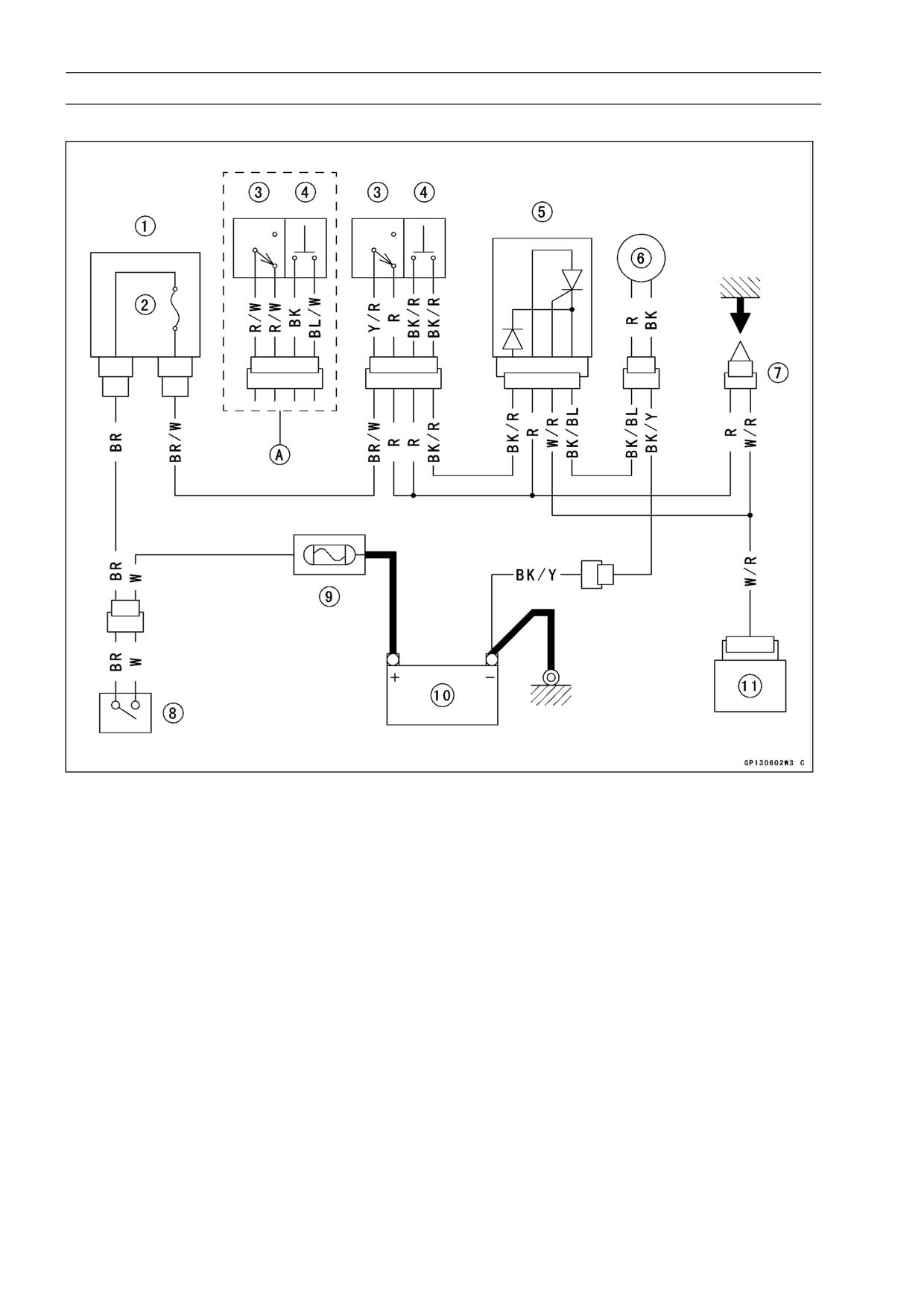
Fuel Pump Circuit
1. Junction Box
2. Ignition Fuse 10 A
3. Engine Stop Switch
4. Starter Button
5. Fuel Pump Relay
6. Fuel Pump
7. Stick Coil
8. Ignition Switch
9. Main Fuse 30 A
10. Battery
11. IC Igniter
A. United States, Canada, Australia and Malaysia Models
ELECTRICAL SYSTEM 15-59
Fuel Cut Valve
The fuel cut valves [A] are adopted for protection of the
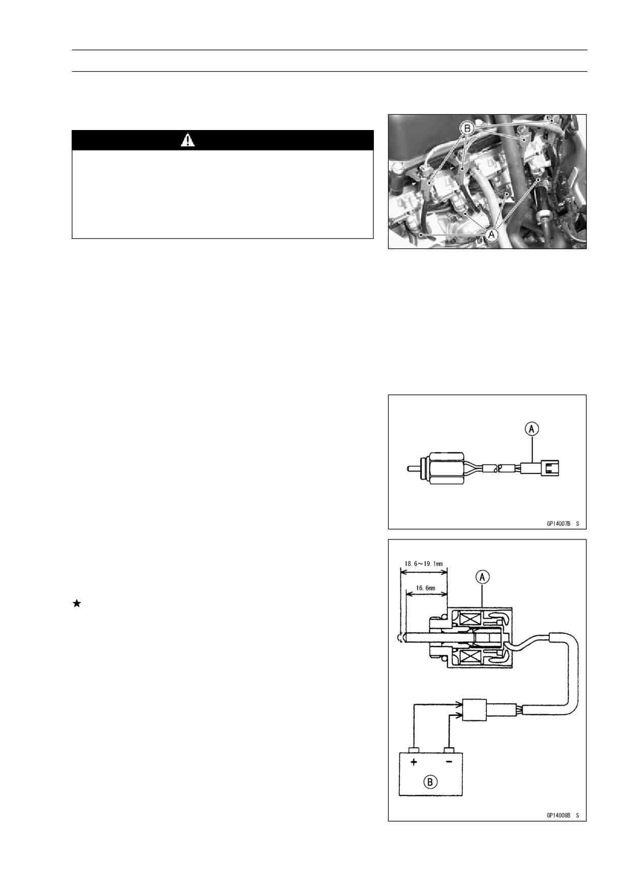
catalytic converter.
Fuel Cut Valve Removal
WARNING
Gasoline is extremely flammable and can be ex-
plosive under certain conditions. Turn the ignition
switch OFF. Do not smoke. Make sure the area is
well-ventilated and free from any source of flame
or sparks; this includes any appliance with a pilot
light.
Remove the fuel tank (see Fuel System chapter).
•
Connect a suitable hose to the fitting at the bottom of each
•
carburetor float bowl.
Run the lower ends of the hoses into a suitable container.
•
Turn out each drain plug a few turns and drain the float
•
bowls.
Special Tool - Carburetor Drain Plug Wrench, Hex
3:
57001-1269
Disconnect the connectors [B] of the fuel cut valves.
•
Loosen the fuel cut valves and remove them.
•
Fuel Cut Valve Installation
Install the fuel cut valves with a gray connector [A] on the
•
#1, #4 carburetors.
Install the fuel cut valves with a brown connector [A] on
•
the #2, #3 carburetors.
Do not install the fuel cut valves on the wrong carburetors.
•
The fuel cut valves will not work well.
Fuel Cut Valve Inspection
Remove the fuel cut valve [A].
•
Connect and disconnect one 12 V battery [B] to the fuel
•
cut valve connector as shown. The valve rod moves.
If the protrusion exceeds the standard (too long or too
short), the valve is defective and must be replaced.
Testing Fuel Cut Valve
Standard Protrusion
When battery is disconnected
→ 16.6 mm (0.65 in.)
When battery is connected
→ 18.6 ∼ 19.1 mm
(0.73 ∼ 0.75 in.)
15-60 ELECTRICAL SYSTEM
Fuel Cut Valve
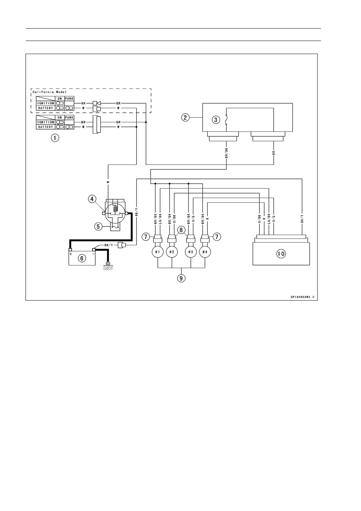
Fuel Cut Valve Circuit
1. Ignition Switch
2. Junction Box
3. Horn Fuse 10 A
4. Starter Relay
5. Main Fuse 30 A
6. Battery
7. Gray Connector
8. Brown Connector
9. Fuel Cut Valve
10. IC Igniter
ELECTRICAL SYSTEM 15-61
Radiator Fan System
WARNING
The radiator fan is connected directly to the battery.
The fan may start even if the ignition switch is off.
NEVER TOUGH THE RADIATOR FAN UNTIL THE
RADIATOR FAN CONNECTOR IS DISCONNECTED.
TOUCHING THE FAN BEFORE THE CONNECTOR
IS DISCONNECTED COULD CAUSE INJURY FROM
THE FAN BLADES.
Fan System Circuit Inspection
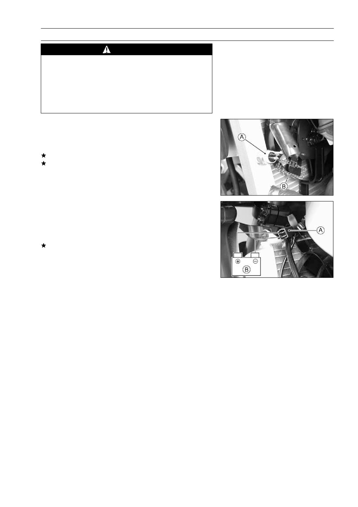
Disconnect the leads from the radiator fan switch [A].
•
Using an auxiliary wire [B], connect the radiator fan switch
•
leads.
If the fan rotates, inspect the fan switch.
If the fan does not rotate, inspect the following.
Leads and Connectors
Main Fuse and Fan Fuse
Fan Motor
Fan Motor Inspection
Remove the left lower fairing (see Frame chapter).
•
Disconnect the 2-pin connector [A] in the fan motor leads.
•
Using two auxiliary wires, supply battery [B] power to the
•
fan motor.
If the fan does not rotate, the fan motor is defective and
must be replaced.
15-62 ELECTRICAL SYSTEM
Radiator Fan System
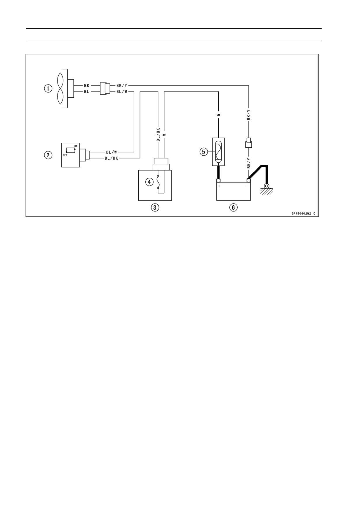
Radiator Fan Circuit
1. Radiator Fan
2. Radiator Fan Switch
3. Junction Box
4. Fan Fuse 10 A
5. Main Fuse 30 A
6. Battery
ELECTRICAL SYSTEM 15-63
Meter, Gauge, Indicator Unit
Meter Unit Removal
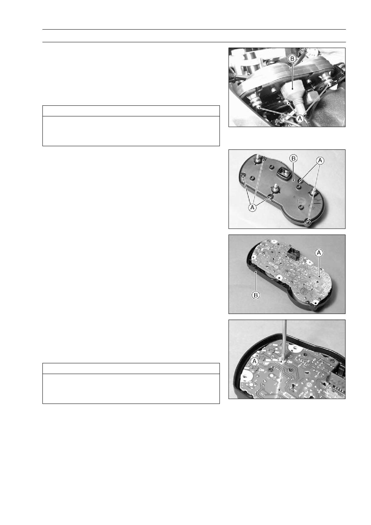
Remove:
•
Windshield (see Handlebar Removal in the Steering
chapter)
Remove the meter unit by taking off the mounting nuts [A]
•
with the washers.
Slide the dust cover [B] and remove the wiring connector.
•
CAUTION
Place the meter unit so that the face is up. If a meter
unit is left upside down or sideways for any length
of time, it will malfunction.
Meter, Gauge Disassembly
Remove:
•
Meter Unit (see Meters, Gauge Removal)
Screws [A]
Lower Meter Cover [B]
Separate the meter assembly [A] and upper meter cover
•
[B].
Bulb Replacement
Remove:
•
Meter Unit
Turn out the socket [A] counterclockwise.
•
Pull the bulb out of the socket.
•
CAUTION
Do not turn the bulb. Pull the bulb out to prevent
damage to the bulb. Do not use bulb rated for
greater wattage than the specified value.
15-64 ELECTRICAL SYSTEM
Meter, Gauge, Indicator Unit
Electronic Combination Meter Unit Inspection
Remove the meter unit.
•
CAUTION
Do not drop the meter unit. Place the meter unit so
that it faces upward. If the meter unit is left upside
down or sideways for a long time or dropped, it will
malfunction.
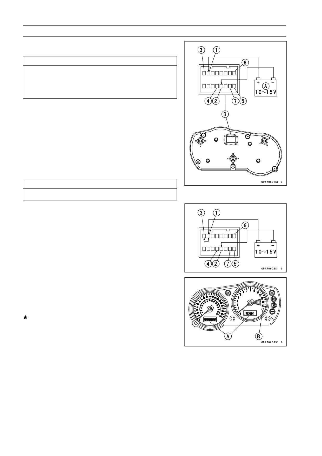
Using the auxiliary wires, connect the 12 V battery [A] to
•
the meter unit connector [B] as follows.
○Connect the battery positive terminal to the terminal [1].
○Connect the battery negative terminal to the terminal [2].
[1] Battery (Positive)
[2] Battery (Negative)
[3] Ignition
[4] Speed Sensor Electric Source
[5] Speed Sensor Pulse
[6] Tachometer Pulse
[7] Water Temperature
CAUTION
Do not short the terminals [2], [4] and [4], [5].
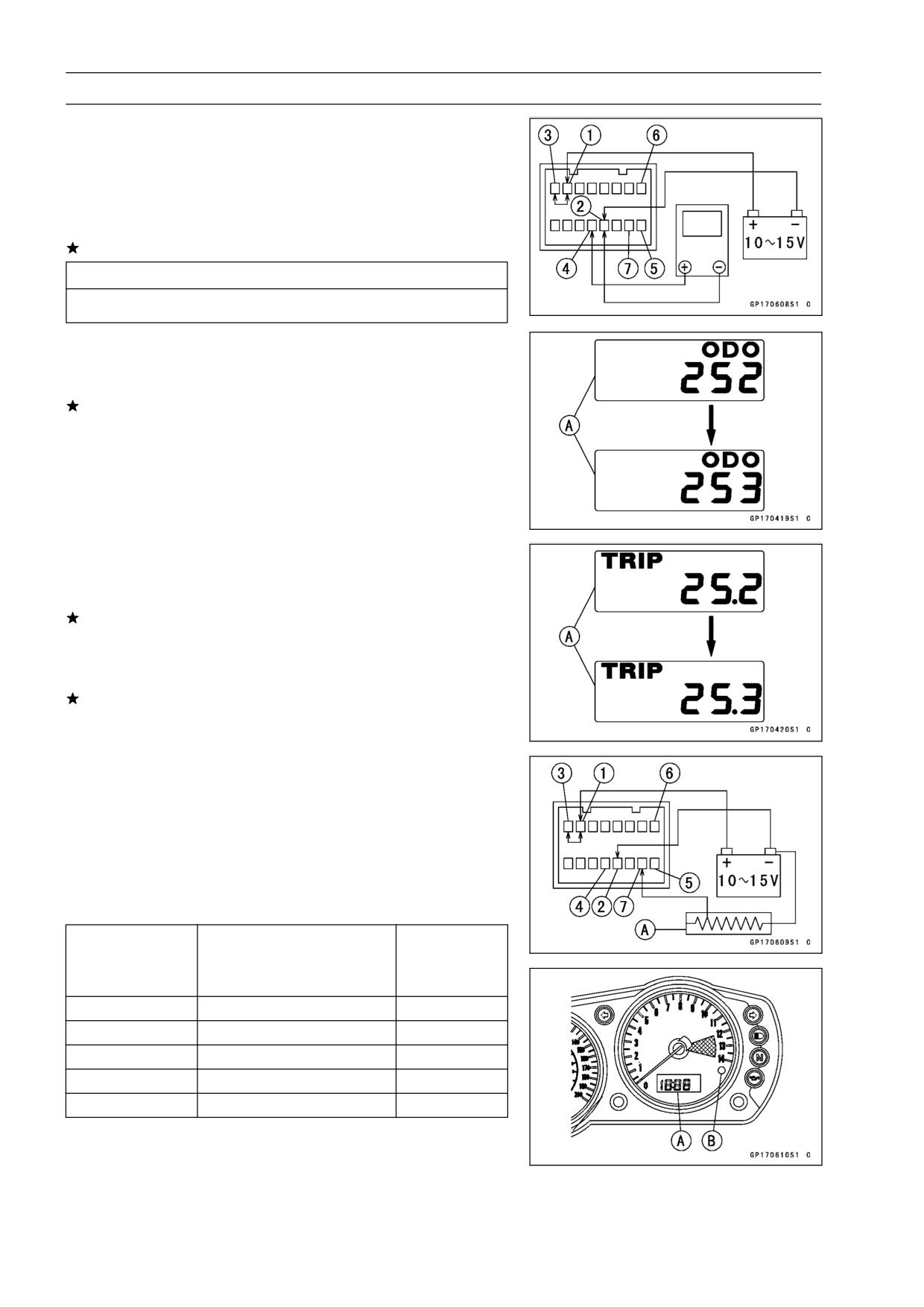
Liquid Crystal Display (LCD) Segments Check
Connect the battery positive terminal to the terminal [1].
•
Connect the battery negative terminal to the terminal [2].
•
Connect the terminal [1] to the terminal [3].
•
○When the terminals are connected, all the LCD segments
[A] and LED warning light [B] appear for three seconds.
○When the terminals are disconnected within three sec-
onds, all the LCD segments and LED warning light disap-
pear.
If the LCD segments and LED warning light will not ap-
pear, replace the meter unit.
ELECTRICAL SYSTEM 15-65
Meter, Gauge, Indicator Unit
ODO/TRIP or CLOCK/TEMP BUTTON Operate Confir-
mation
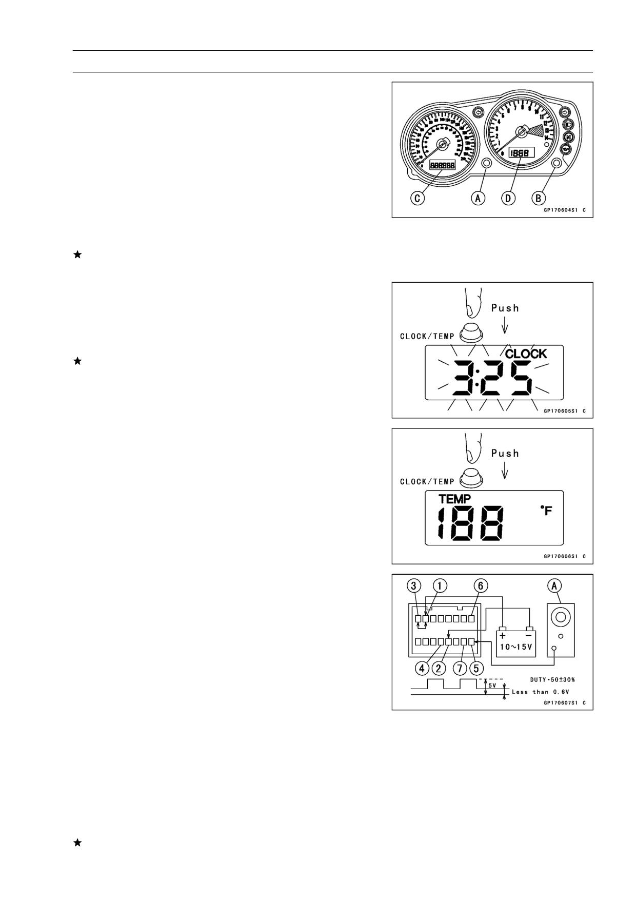
Connect the 12 V battery and terminals in the same man-
•
ner as specified in the "Liquid Crystal Display (LCD) Seg-
ments Check".
Check that when the button [A] or [B] is pushed and held
•
continuously, the display [C] or [D] turns an other mode
within two seconds.
[A] ODO/TRIP
[B] CLOCK/TEMP
[C] ODO METER → TRIP METER → ODO METER
[D] CLOCK → TEMPERATURE → CLOCK
If the display function does not work, replace the meter
unit.
Indicate the clock mode.
•
Check that when the button in CLOCK mode is pushed
•
for more than two seconds, the meter display turns to the
clock set mode.
Check that it is possible to adjust hours and minutes.
•
If the display function does not work and adjust, replace
the meter unit.
Indicate the temp mode.
•
Check that when the button in TEMP mode is pushed for
•
more than two seconds, the figure display turns to Celsius
degree or Fahrenheit degree of water temperature.
Speedometer Check
Connect the 12 V battery and terminals in the same man-
•
ner as specified in the "Liquid Crystal Display (LCD) Seg-
ments Check".
The speed equivalent to the input frequency is indicated in
•
the oscillator [A] if the square wave (illustrated as shown)
would be input into the terminal [5].
○Indicates approximately 60 mph in case the input fre-
quency would be approximately 146 Hz.
○Indicates approximately 60 km/h in case the input fre-
quency would be approximately 91 Hz.
If the oscillator is not available, the speedometer can be
•
checked as follows.
○Install the meter unit.
○Raise the rear wheel off the ground, using the jack.
○Turn on the ignition switch.
○Rotate the rear wheel by hand.
○Check that the speedometer shows the speed.
If the speedometer does not work, check the speed sen-
sor electric source voltage and speed sensor.
15-66 ELECTRICAL SYSTEM
Meter, Gauge, Indicator Unit
Speed Sensor Electric Source Check
Connect the 12 V battery and terminals in the same man-
•
ner as specified in the "Liquid Crystal Display (LCD) Seg-
ments Check".
Set the hand tester to the DC25 V range and connect it to
•
the terminals [2] and [4].
If the voltage is less than 7 V, replace the meter unit.
CAUTION
Do not short the terminals [2], [4] and [4], [5].
Odometer Check
Check the odometer with the speedometer in the same
•
way.
If value indicated in the odometer is not added, replace
the meter unit.
Trip Meter Check
Check the trip meter with the speedometer in the same
•
way.
If value indicated in the trip meter is not added, replace
the meter unit.
Check that when the ODO/TRIP button is pushed for more
•
than two seconds, the figure display turns to 0.0.
If the figure display does not indicate 0.0, replace the me-
ter unit.
Water Temperature Meter Check
Connect the 12 V battery and terminals in the same man-
•
ner as specified in the "Liquid Crystal Display (LCD) Seg-
ments Check".
Connect the variable rheostat [A] to the terminal [7] as
•
shown.
Check that the number of segments matches the resis-
•
tance value of the variable rheostat.
Resistance Value
Warning Light
Temperature METER [A]
(Ω)
[B]
9560
50°C (122°F)
OFF
2780
80°C (176°F)
OFF
950
110°C (230°F)
OFF
810
115°C (239°F)
ON
690
HI
Flash
If any display function does not work, replace the meter
•
unit.
ELECTRICAL SYSTEM 15-67
Meter, Gauge, Indicator Unit
Tachometer Check
Connect the 12 V battery and terminals in the same man-
•
ner as specified in the "Liquid Crystal Display (LCD) Seg-
ments Check".
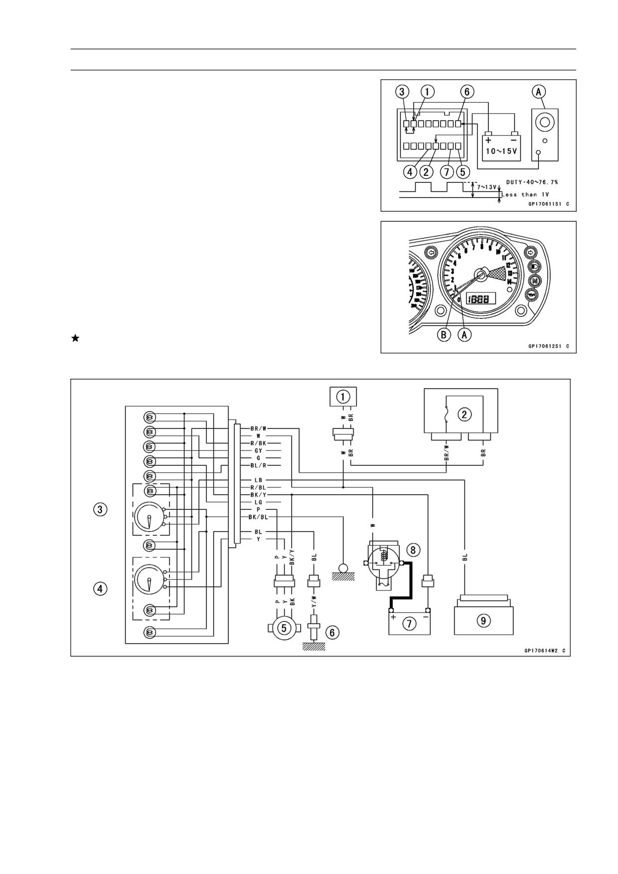
The revolutions per minute (rpm) equivalent to the input
•
frequency is indicated in the oscillator [A] if the square
wave (illustrated as shown) would be input into the termi-
nal [6].
○Indicates approximately 6000 rpm in case the input fre-
quency would be approximately 200 Hz.
If the oscillator is not available, the tachometer can be
•
checked as follows.
○Connect the 12 V battery and terminals in the same man-
ner as specified in the "Liquid Crystal Display (LCD) Seg-
ments Check".
○Using an auxiliary wire, open and connect the terminal [1]
to the terminal [6] repeatedly.
○Then the tachometer hand [A] should flick [B].
If the hand does not flick, replace the meter unit.
Meter Circuit
1. Ignition Switch
2. Junction Box
3. Tachometer
4. Speedometer
5. Speed Sensor
6. Water Temperature Sensor
7. Battery
8. Main Fuse (30 A)
9. IC Igniter
15-68 ELECTRICAL SYSTEM
Switches and Sensors
Brake Light Timing Inspection
Turn on the ignition switch.
•
Check the operation of the rear brake light switch by de-
•
pressing the brake pedal.
If it does not as specified, adjust the brake light timing.
Brake Light Timing
Standard:
On after about 10 mm (3.94 in.) of pedal
travel [A]
Brake Light Timing Adjustment
Brake light timing is adjusted by changing the position of
the rear brake light switch.
Adjust the position of the switch so that the brake light
•
goes on after the specified pedal travel by turning the ad-
justing nut [A].
CAUTION
To avoid damaging the electrical connections in-
side the switch, be sure that the switch body does
not turn during adjustment.
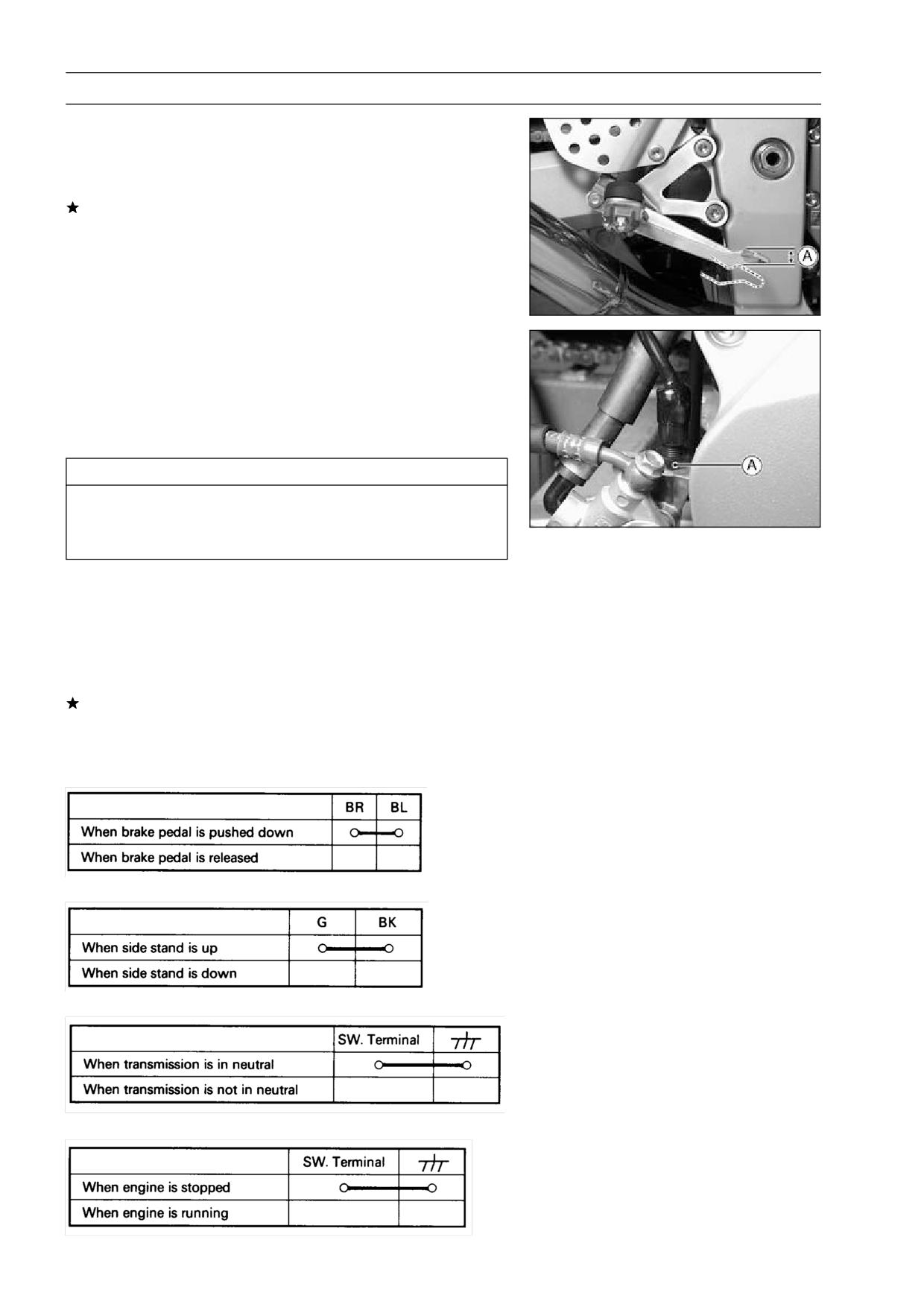
Switch Inspection
Using a hand tester, check to see that only the con-
•
nections shown in the table have continuity (about zero
ohms).
○For the handlebar switches and the ignition switch, refer
to the tables in the Wiring Diagram.
If the switch has an open or short, repair it or replace it
with a new one.
Special Tool - Hand Tester: 57001-1394
Rear Brake Light Switch Connections
Side Stand Switch Connections
Neutral Switch Connections
Oil Pressure Switch Connections*
*: Engine lubrication system is in good condition
ELECTRICAL SYSTEM 15-69
Switches and Sensors
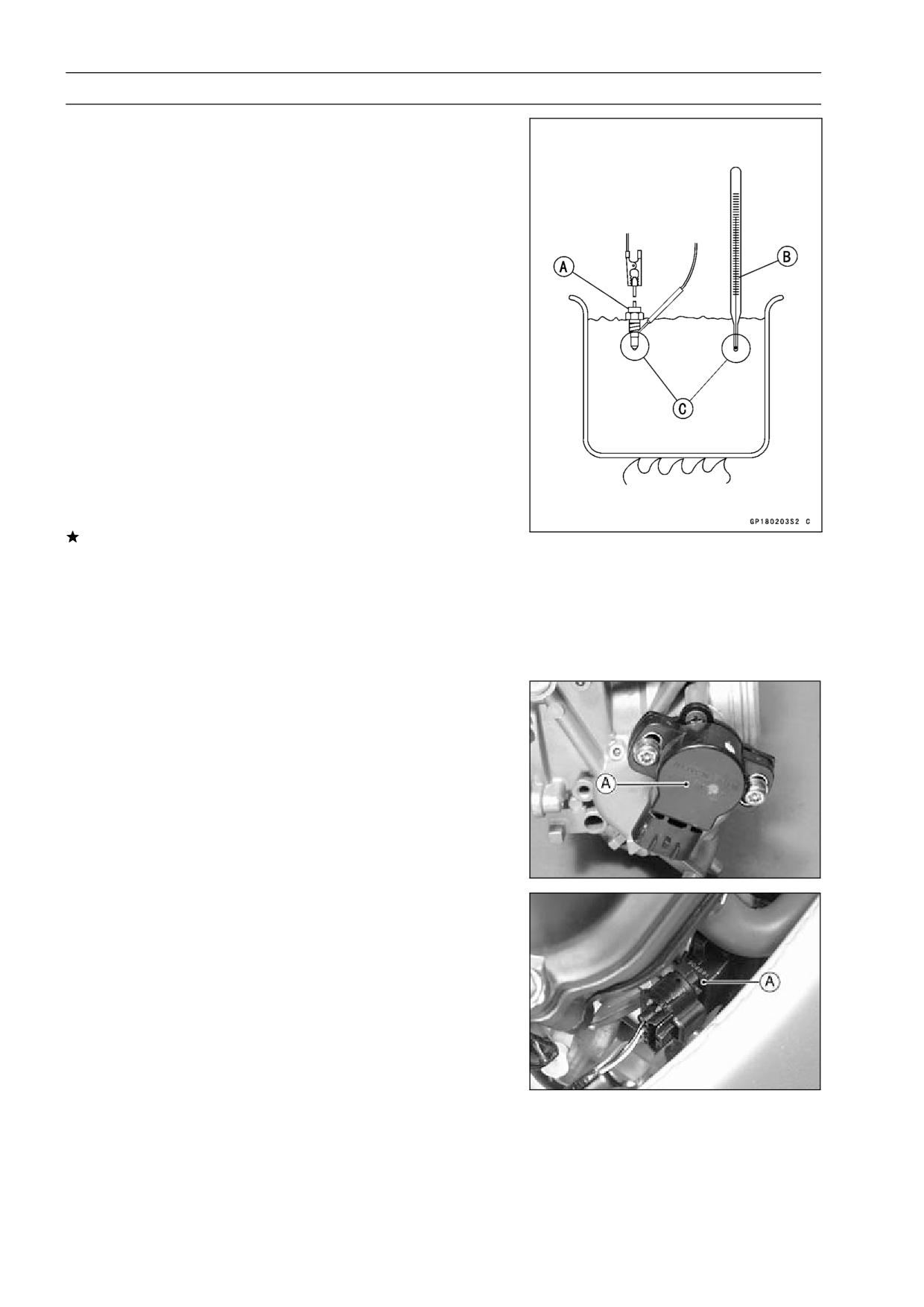
Radiator Fan Switch Inspection
Remove the fan switch (see Cooling System chapter).
•
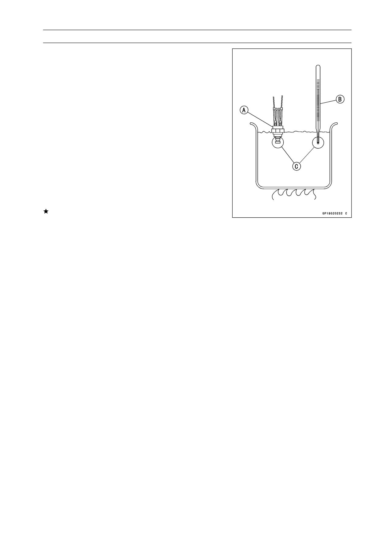
Suspend the switch [A] in a container of coolant so that
•
the temperature-sensing projection and threaded portion
are submerged.
Suspend an accurate thermometer [B] in the coolant so
•
that the sensitive portions [C] are located in almost the
same depth.
NOTE
○The switch and thermometer must not touch the con-
tainer sides or bottom.
Place the container over a source of heat and gradu-
•
ally raise the temperature of the coolant while stirring the
coolant gently.
Using the hand tester, measure the internal resistance
•
of the switch across the terminals at the temperatures
shown in the table.
Special Tool - Hand Tester: 57001-1394
If the hand tester does not show the specified values, re-
place the switch.
Fan Switch Resistance
○Rising temperature:
From OFF to ON at 96 ∼ 100°C (205 ∼ 212°F)
○Falling temperature:
From ON to OFF at 91°C (196°F) or less
ON: Less than 0.5 Ω
OFF: More than 1 MΩ
15-70 ELECTRICAL SYSTEM
Switches and Sensors
Water Temperature Sensor Inspection
Remove the water temperature sensor (see Cooling Sys-
•
tem chapter).
Suspend the sensor [A] in a container of coolant so that
•
the temperature-sensing projection and threaded portion
are submerged.
Suspend an accurate thermometer [B] in the coolant so
•
that the sensitive portions [C] are located in almost the
same depth.
NOTE
○The sensor and thermometer must not touch the con-
tainer side or bottom.
Place the container over a source of heat and gradu-
•
ally raise the temperature of the coolant while stirring the
coolant gently.
Using the hand tester, measure the internal resistance of
•
the sensor across the terminal and the body at the tem-
peratures shown in the table.
Special Tool - Hand Tester: 57001-1394
If the hand tester does not show the specified values, re-
place the sensor.
Water Temperature Sensor Resistance
50°C (122°F):
9.18 ∼ 9.94 kΩ
80°C (176°F):
2.50 ∼ 3.06 kΩ
120°C (248°F):
0.65 ∼ 0.73 kΩ
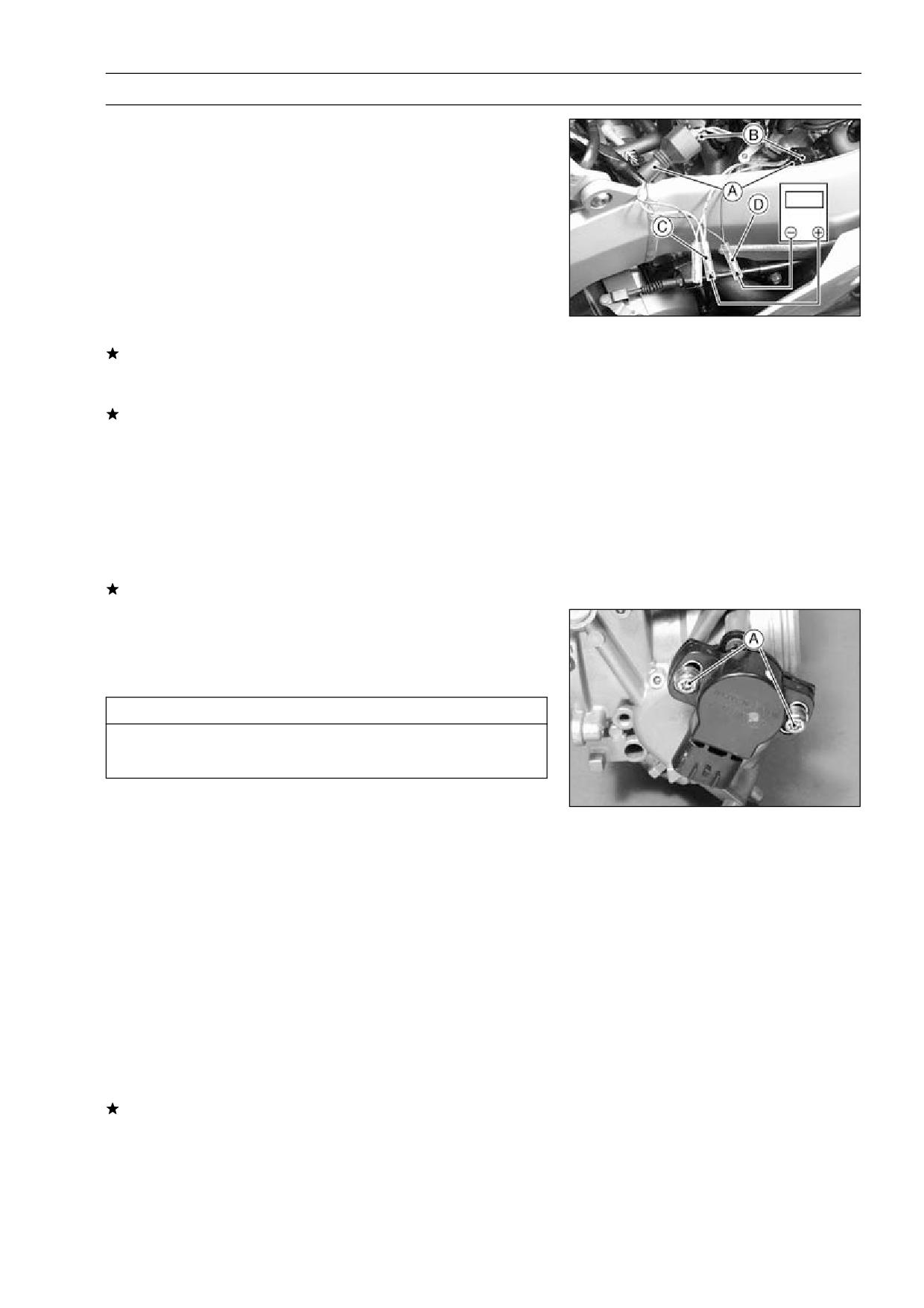
Throttle Sensor Removal/Installation
Remove the carburetors (see Fuel System chapter).
•
Remove the throttle sensor [A] by unscrewing the mount-
•
ing screws.
Be sure to adjust the throttle sensor when installing (see
•
Throttle Sensor Adjustment).
Throttle Sensor Inspection
Remove the fuel tank (see Fuel System chapter).
•
Prepare an auxiliary fuel tank and connect the fuel hose
•
to the carburetors.
Start the engine and warm it up thoroughly.
•
Check:
•
Idle Speed (see Fuel System chapter)
Battery Charging Condition (see this chapter)
Turn off the ignition switch.
•
Remove the throttle sensor lead connector [A].
•
ELECTRICAL SYSTEM 15-71
Switches and Sensors
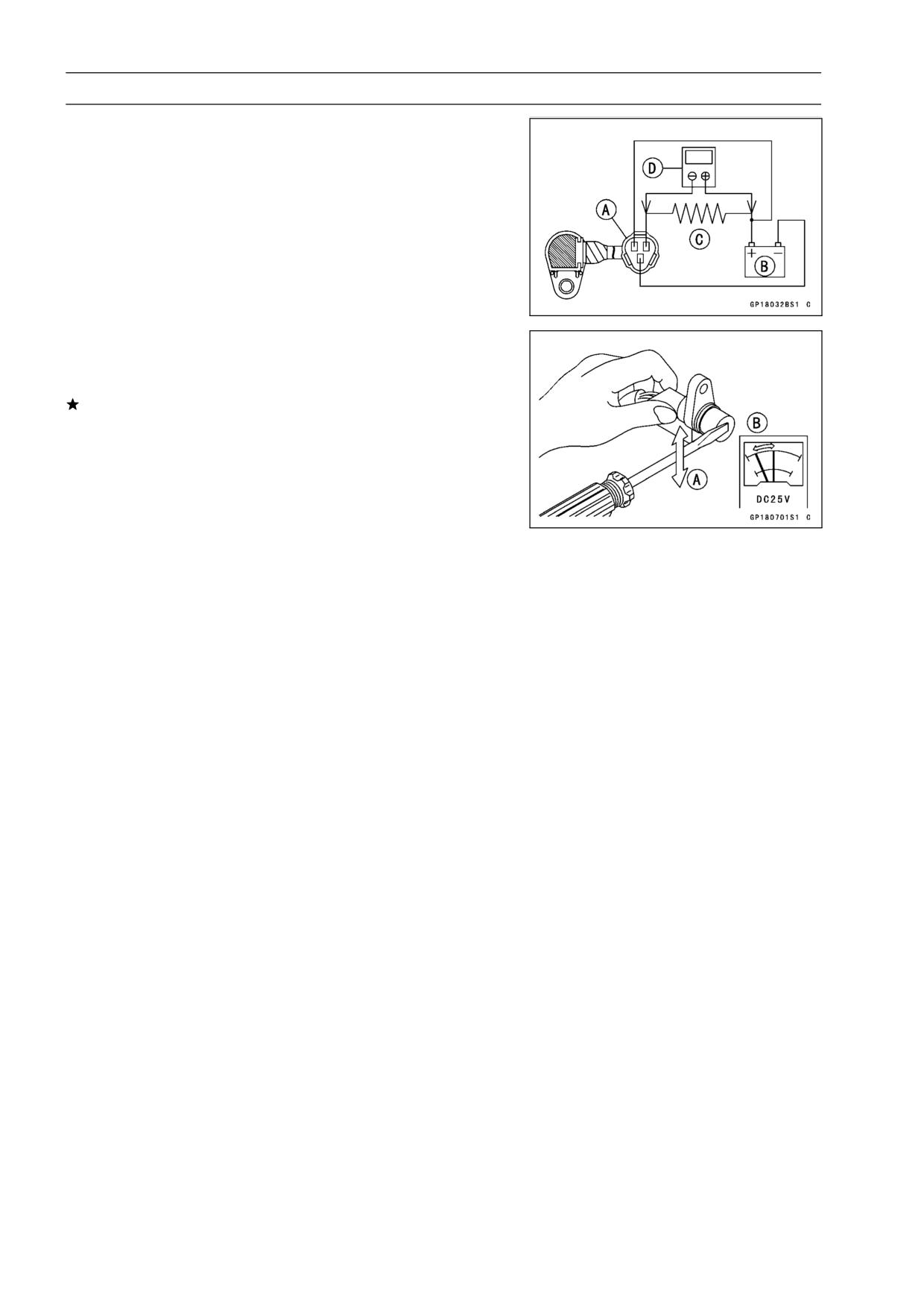
Connect the adapter [B] between the connectors [A].
•
Special Tool - Throttle Sensor Setting Adapter:
57001
-1521
Connect the hand tester to the adapter.
•
Hand Tester (+) → Y/W Lead [C]
Hand Tester (-) → BK/BL Lead [D]
Starter the engine.
•
Check the sensor output voltage with the engine idling.
•
Throttle Sensor Output Voltage
Standard:
0.95 ∼ 1.05 V (When engine is idling.)
If it is not within the specified voltage, adjust the throt-
tle sensor position (see Throttle Sensor Position Adjust-
ment).
If it is specified voltage, go to next test.
Stop the engine.
•
Turn on the ignition switch.
•
Check the sensor output voltage with the throttle fully
•
open.
Throttle Sensor Output Voltage
Standard:
3.95 ∼ 4.15 V (When throttle is fully
opened.)
If it is not within the specified voltage, replace the sensor.
Throttle Sensor Position Adjustment
Start the engine.
•
Check idle speed (see Fuel System chapter).
•
Stop the engine and remove the carburetor.
•
CAUTION
Do not turn the idle adjusting screw when removing
the carburetor.
Connect the throttle sensor setting adapter to the sensor
•
lead connectors (see Throttle Sensor Inspection).
Special Tool - Throttle Sensor Setting Adapter:
57001
-1521
Loosen the throttle sensor mounting screws [A].
•
Turn on the ignition switch.
•
When installing the sensor, tighten the screws gradually
•
and alternately.
Torque - Throttle Sensor mounting Screw: 3.4 N·m (0.35
kgf·m, 30 in·lb)
Adjust the position of the throttle sensor until the output
•
voltage is within the specified voltage.
Throttle Sensor Output Voltage
Standard:
0.95 ∼ 1.05 V
If it is not within the specified voltage, replace the sensor.
When installing the sensor, tighten the screws gradually
•
and alternately.
Torque - Throttle Sensor Mounting Screw: 3.4 N·m (0.35
kgf·m, 30 in·lb)
15-72 ELECTRICAL SYSTEM
Switches and Sensors
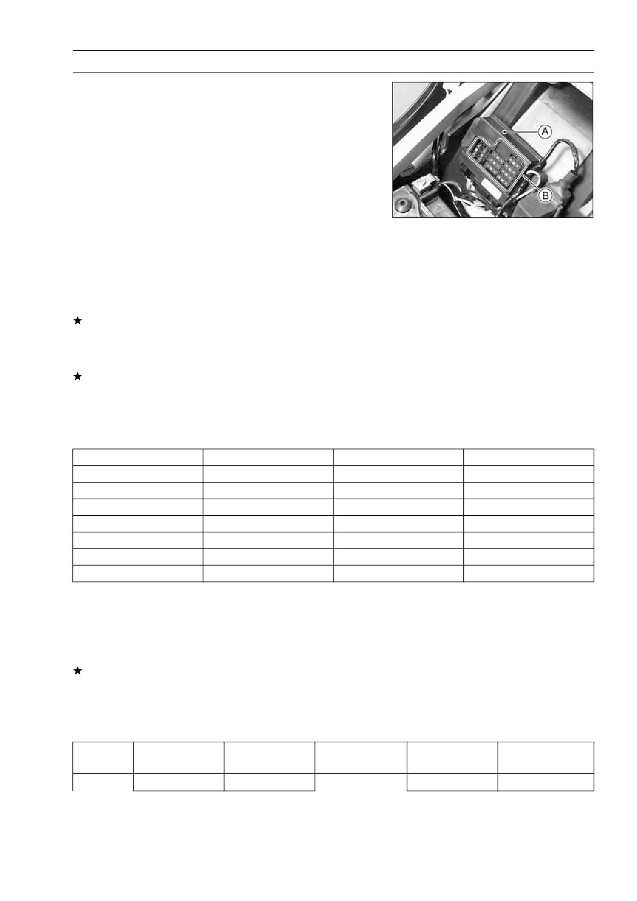
Speed Sensor Inspection
Remove:
•
Speed Sensor (see Final Drive chapter)
Connect the speed sensor connector [A] with the battery
•
[B], 10 kΩ resistor [C] and hand tester [D] as shown.
Set the tester to the DC 25 V range.
•
Special Tool - Hand Tester: 57001-1394
Trace [A] each side of the speed sensor surface with the
•
screw driver.
○Then the tester indicator should flick [B].
If the tester indicator does not flick, replace the speed
sensor.
ELECTRICAL SYSTEM 15-73
Junction Box
The junction box [A] has fuses [B], relays, and diodes.
The relays and diodes can not be removed.
Junction Box Fuse Circuit Inspection
Remove the seats (see Frame chapter).
•
Remove the junction box.
•
Pull off the connectors from the junction box.
•
Make sure all connector terminals are clean and tight, and
•
none of them have been bent.
Clean the dirty terminals, and straighten slightly-bent ter-
minals.
Check conductivity of the numbered terminals with the
•
hand tester.
If the tester does not read as specified, replace the junc-
tion box.
Special Tool - Hand Tester: 57001-1394
Fuse Circuit Inspection
Tester Connection
Tester Reading (Ω)
Tester Connection
Tester Reading (Ω)
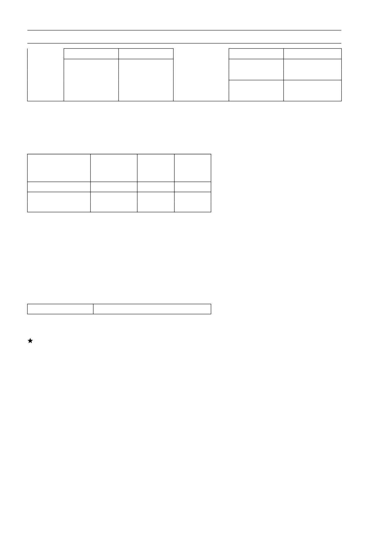
1-1A
0
1A-8
∞
1-2
0
2-8
∞
3A-4
0
3A-8
∞
6-5
0
6-2
∞
6-10
0
6-3A
∞
6-7
0
17-3A
∞
6-17
0
Starter Circuit/Headlight Relay Inspection
Remove the junction box.
•
Check conductivity of the following numbered terminals
•
by connecting the hand tester and one 12 V battery to the
junction box as shown.
If the tester does not read as specified, replace the junc-
tion box.
Special Tool - Hand Tester: 57001-1394
Relay Circuit Inspection (with the battery disconnected)
Tester
Tester Reading
Tester
Tester Reading
Connection
(Ω)
Connection
(Ω)
*7 - 8
∞
9 - 11
∞
15-74 ELECTRICAL SYSTEM
Junction Box
*7 - 13
∞
12 - 13
∞
Starter Circuit
Headlight
(+) (-)
(+) (-)
Relay
Relay
*13 - 9
Not ∞ **
13 - 11
∞
(+) (-)
12 - 11
Not ∞ **
(*): United States, Canada, Australia , and Malaysia Models only
(**): The actual reading varies with the hand tester used.
(+): Apply tester positive lead.
(-): Apply tester negative lead.
Relay Circuit Inspection (with the battery connected)
Battery
Tester
Tester
Connection
Connection
Reading
(+) (-)
(Ω)
Headlight Relay
*9-13
*7-8
0
(+) (-)
Starter Circuit Relay
11-12
13-11
Not ∞ **
(*): United States, Canada, Australia , and Malaysia Mod-
els only
(**): The actual reading varies with the hand tester used.
(+): Apply tester positive lead.
(-): Apply tester negative lead.
Diode Circuit Inspection
Remove the junction box.
•
Check conductivity of the following pairs of terminals.
•
Diode Circuit Inspection
Tester Connection
*13-8, *13-9, 12-11, 12-14, 15-14, 16-14
*: United States, Canada, Australia, and Malaysia Mod-
els only
The resistance should be low in one direction and more
than ten times as much in the other direction. If any diode
shows low or high in both directions, the diode is defective
and the junction box must be replaced.
NOTE
○The actual meter reading varies with the meter used
and the individual diodes, but, generally speaking, the
lower reading should be from zero to one half the scale.
ELECTRICAL SYSTEM 15-75
Junction Box
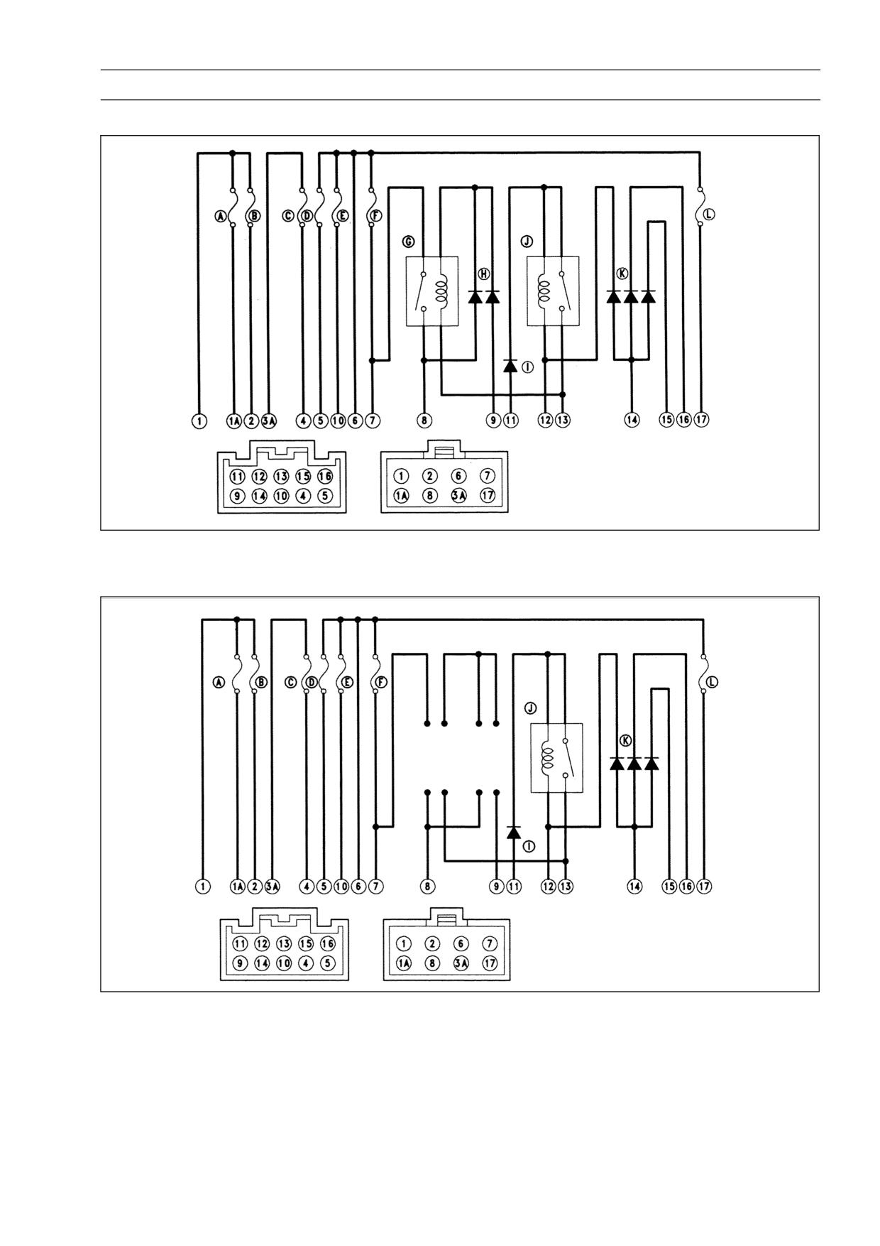
Junction Box Internal Circuit (United States, Canada, Australia, and Malaysia)
Junction Box Internal Circuit (Other than United States, Canada, Australia, and
Malaysia)
A. Accessory Fuse 10 A
G. Headlight Relay
B. Fan Fuse 10 A
H. Headlight Diodes
C. Turn Signal Relay Fuse 10 A
I. Starter Diode
D. Horn Fuse 10 A
J. Starter Circuit Relay
E. Ignition Fuse 10 A
K. Interlock Diodes
F. Headlight Fuse 10 A
L. Taillight Fuse 10 A
15-76 ELECTRICAL SYSTEM
Fuse
30 A Main Fuse Removal
Remove:
•
Seats (see Frame chapter)
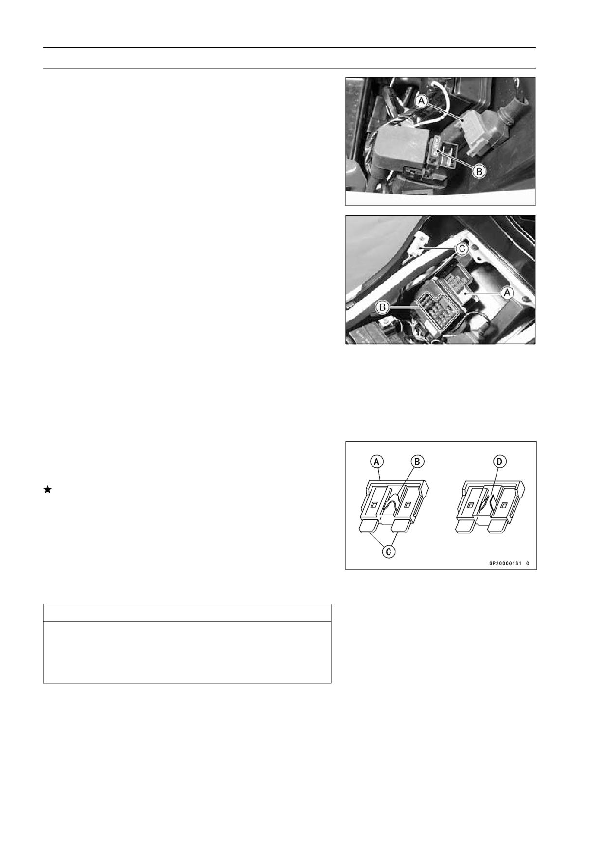
Starter Relay and 30 A Main Fuse Connector [A]
Pull out the main fuse [B] from the starter relay with needle
•
nose pliers.
Junction Box Fuse Removal
Remove the seats (see Frame chapter).
•
Unlock the hook to lift up the lid [A].
•
Pull the fuses [B] straight out of the junction box with nee-
•
dle nose pliers.
C: Headlight Fuse
Fuse Installation
If a fuse fails during operation, inspect the electrical sys-
•
tem to determine the cause, and then replace it with a
new fuse of proper amperage.
Install the junction box fuses on the original position as
•
specified on the lid.
Fuse Inspection
Remove the fuse (see Fuse Removal).
•
Inspect the fuse element.
•
If it is blown out, replace the fuse. Before replacing a
blown fuse, always check the amperage in the affected
circuit. If the amperage is equal to or greater than the
fuse rating, check the wiring and related components for
a short circuit.
Housing [A]
Fuse Element [B]
Terminals [C]
Blown Element [D]
CAUTION
When replacing a fuse, be sure the new fuse
matches the specified fuse rating for that circuit.
Installation of a fuse with a higher rating may cause
damage to wiring and components.
APPENDIX 16-1
Appendix
Table of Contents
Troubleshooting Guide
16-2
General Lubrication
16-7
Lubrication
16-7
Nut, Bolt, and Fastener Tightness
16-8
Tightness Inspection
16-8
Unit Conversion Table
16-9
16
16-2 APPENDIX
Troubleshooting Guide
NOTE
Spark plug cap shorted or not in good con-
○This is not an exhaustive list, giving every
tact
possible cause for each problem listed. It
Spark plug incorrect
is meant simply as a rough guide to assist
IC igniter trouble
the troubleshooting for some of the more
Cam sensor trouble
common difficulties.
Neutral, starter lockout, or sidestand switch
trouble
Engine Doesn’t Start, Starting
Crankshaft sensor trouble
Difficulty:
Stick coil trouble
Starter motor not rotating:
Ignition or engine stop switch shorted
Starter lockout switch or neutral switch trou-
Wiring shorted or open
ble
Fuse blown
Starter motor trouble
Fuel/air mixture incorrect:
Battery voltage low
Pilot screw and/or idle adjusting screw mal-
Starter relays not contacting or operating
adjusted
Starter button not contacting
Pilot jet, or air passage clogged
Wiring open or shorted
Air cleaner clogged, poorly sealed, or miss-
Ignition switch trouble
ing
Engine stop switch trouble
Starter jet clogged
Fuse blown
Compression Low:
Starter motor rotating but engine doesn’t
Spark plug loose
turn over:
Cylinder head not sufficiently tightened
Starter clutch trouble
down
Engine won’t turn over:
No valve clearance
Valve seizure
Cylinder, piston worn
Valve lifter seizure
Piston ring bad (worn, weak, broken, or
Cylinder, piston seizure
sticking)
Crankshaft seizure
Piston ring/groove clearance excessive
Connecting rod small end seizure
Cylinder head gasket damaged
Connecting rod big end seizure
Cylinder head warped
Transmission gear or bearing seizure
Valve spring broken or weak
Camshaft seizure
Valve not seating properly (valve bent,
Starter idle gear seizure
worn, or carbon accumulation on the
No fuel flow:
seating surface)
No fuel in tank
Battery voltage low
Poor Running at Low Speed:
Fuel pump trouble
Spark weak:
Fuel pump relay trouble
Battery voltage low
Fuel tank air vent obstructed
Spark plug dirty, broken, or maladjusted
Fuel filter clogged
Stick coil wiring trouble
Fuel tap clogged
Stick coil not in good contact
Fuel line clogged
Spark plug incorrect
Float valve clogged
IC igniter trouble
Fuel cut valve left close (check fuel cut
Crankshaft sensor trouble
valve and IC igniter)
Stick coil trouble
Engine flooded:
Fuel/air mixture incorrect:
Fuel level in carburetor float bowl too high
Pilot screw maladjusted
Float valve worn or stuck open
Pilot jet, or air passage clogged
Starting technique faulty
Air bleed pipe bleed holes clogged
(When flooded, crank the engine with the
Pilot passage clogged
throttle fully opened to allow more air to
Air cleaner clogged, poorly sealed, or miss-
reach the engine.)
ing
No spark; spark weak:
Choke plunger stuck open
Battery voltage low
Fuel level in carburetor float bowl too high
Spark plug dirty, broken, or maladjusted
or too low
Spark plug cap or high tension wiring trou-
Fuel tank air vent obstructed
ble
APPENDIX 16-3
Troubleshooting Guide
Fuel cut valve won’t fully open (check fuel
Air cleaner clogged, poorly sealed, or miss-
cut valve and IC igniter)
ing
Carburetor holder loose
Air cleaner duct loose
Air cleaner duct loose
Air cleaner O-ring damaged
Air cleaner O-ring damaged
Water or foreign matter in fuel
Fuel pump trouble
Carburetor holder loose
Fuel pump relay trouble
Fuel to carburetor insufficient
Fuel filter clogged
Fuel tank air vent obstructed
Compression low:
Fuel tap clogged
Spark plug loose
Fuel line clogged
Cylinder head not sufficiently tightened
Fuel pump trouble
down
Fuel pump relay trouble
No valve clearance
Fuel filter clogged
Cylinder, piston worn
Compression low:
Piston ring bad (worn, weak, broken, or
Spark plug loose
sticking)
Cylinder head not sufficiently tightened
Piston ring/groove clearance excessive
down
Cylinder head warped
No valve clearance
Cylinder head gasket damaged
Cylinder, piston worn
Valve spring broken or weak
Piston ring bad (worn, weak, broken, or
Valve not seating properly (valve bent,
sticking)
worn, or carbon accumulation on the
Piston ring/groove clearance excessive
seating surface)
Cylinder head gasket damaged
Other:
Cylinder head warped
IC igniter trouble
Valve spring broken or weak
Carburetor not synchronizing
Valve not seating properly (valve bent,
Carburetor vacuum piston doesn’t slide
worn, or carbon accumulation on the
smoothly
seating surface.)
Carburetor vacuum piston diaphragm dam-
Knocking:
age
Carbon built up in combustion chamber
Engine oil viscosity too high
Fuel poor quality or incorrect
Drive train trouble
Spark plug incorrect
Brake dragging
IC igniter trouble
Air suction valve trouble
Miscellaneous:
Vacuum switch valve trouble
Throttle valve won’t fully open
Carburetor vacuum piston doesn’t slide
Poor Running or No Power at High
smoothly
Speed:
Carburetor vacuum piston diaphragm dam-
Firing incorrect:
aged
Spark plug dirty, broken, or maladjusted
Brake dragging
Stick coil wiring trouble
Clutch slipping
Stick coil not in good contact
Overheating
Spark plug incorrect
Engine oil level too high
IC igniter trouble
Engine oil viscosity too high
Crankshaft sensor trouble
Drive train trouble
Stick coil trouble
Air suction valve trouble
Fuel/air mixture incorrect:
Vacuum switch valve trouble
Choke plunger stuck open
Catalytic converters melt down due to muf-
Main jet clogged or wrong size
fler overheating (KLEEN)
Jet needle or needle jet worn
Air jet clogged
Overheating:
Fuel level in carburetor float bowl too high
Firing incorrect:
or too low
Spark plug dirty, broken, or maladjusted
Fuel cut valve won’t fully open (check fuel
Spark plug incorrect
cut valve)
IC Igniter trouble
Bleed holes of needle jet holder or needle
jet clogged
16-4 APPENDIX
Troubleshooting Guide
Muffler overheating:
Over Cooling:
For KLEEN, do not run the engine even if
Gauge incorrect:
with only one cylinder misfiring or poor
Water temperature meter broken
running (Request the nearest service fa-
Water temperature sensor broken
cility to correct it)
Cooling system component incorrect:
For KLEEN, do not push-start with a dead
Radiator fan switch trouble
battery (Connect another full-charged
Thermostat trouble
battery with jumper cables, and start the
engine using the electric starter)
Clutch Operation Faulty:
For KLEEN, do not start the engine under
Clutch slipping:
misfire due to spark plug fouling or poor
Friction plate worn or warped
connection of the stick coil
Steel plate worn or warped
For KLEEN, do not coast the motorcycle
Clutch spring broken or weak
with the ignition switch off (Turn the igni-
Clutch hub or housing unevenly worn
tion switch ON and run the engine)
No clutch lever play
IC igniter or fuel cut valve trouble
Clutch inner cable trouble
IC igniter trouble
Clutch release mechanism trouble
Fuel/air mixture incorrect:
Clutch not disengaging properly:
Main jet clogged or wrong size
Clutch plate warped or too rough
Fuel level in carburetor float bowl too low
Clutch spring compression uneven
Carburetor holder loose
Engine oil deteriorated
Air cleaner duct loose
Engine oil viscosity too high
Air cleaner poorly sealed, or missing
Engine oil level too high
Air cleaner O-ring damaged
Clutch housing frozen on drive shaft
Air cleaner clogged
Clutch hub nut loose
Fuel pump trouble
Clutch hub spline damaged
Fuel pump relay trouble
Clutch friction plate installed wrong
Fuel filter clogged
Clutch lever play excessive
Compression high:
Clutch release mechanism trouble
Carbon built up in combustion chamber
Engine load faulty:
Gear Shifting Faulty:
Clutch slipping
Doesn’t go into gear; shift pedal doesn’t
Engine oil level too high
return:
Engine oil viscosity too high
Clutch not disengaging
Drive train trouble
Shift fork bent or seized
Brake dragging
Gear stuck on the shaft
Lubrication inadequate:
Gear positioning lever binding
Engine oil level too low
Shift return spring weak or broken
Engine oil poor quality or incorrect
Shift return spring pin loose
Oil cooler incorrect:
Shift mechanism arm spring broken
Oil cooler clogged
Shift mechanism arm broken
Gauge incorrect:
Shift pawl broken
Water temperature meter broken
Jumps out of gear:
Water temperature sensor broken
Shift fork ear worn, bent
Coolant incorrect:
Gear groove worn
Coolant level too low
Gear dogs and/or dog holes worn
Coolant deteriorated
Shift drum groove worn
Cooling system component incorrect:
Gear positioning lever spring weak or bro-
Radiator fin damaged
ken
Radiator clogged
Shift fork guide pin worn
Thermostat trouble
Drive shaft, output shaft, and/or gear
Radiator cap trouble
splines worn
Radiator fan switch trouble
Overshifts:
Fan motor broken
Gear positioning lever spring weak or bro-
Fan blade damaged
ken
Water pump not turning
Shift mechanism arm spring broken
Water pump impeller damaged
APPENDIX 16-5
Troubleshooting Guide
Abnormal Engine Noise:
Rear wheel misaligned
Knocking:
IC igniter trouble
Abnormal Frame Noise:
Carbon built up in combustion chamber
Front fork noise:
Fuel poor quality or incorrect
Oil insufficient or too thin
Spark plug incorrect
Spring weak or broken
Overheating
Rear shock absorber noise:
Piston slap:
Shock absorber damaged
Cylinder/piston clearance excessive
Disc brake noise:
Cylinder, piston worn
Pad installed incorrectly
Connecting rod bent
Pad surface glazed
Piston pin, piston pin hole worn
Disc warped
Valve noise:
Caliper trouble
Valve clearance incorrect
Other noise:
Valve spring broken or weak
Bracket, nut, bolt, etc.
not properly
Camshaft bearing worn
mounted or tightened
Valve lifter worn
Other noise:
Oil Pressure Warning Light Goes On:
Connecting rod small end clearance exces-
Engine oil pump damaged
sive
Engine oil screen clogged
Connecting rod big end clearance exces-
Engine oil level too low
sive
Engine oil viscosity too low
Piston ring/groove clearance excessive
Camshaft bearing worn
Piston ring worn, broken, or stuck
Crankshaft bearings worn
Piston ring groove worn
Oil pressure switch damaged
Piston seizure, damage
Wiring faulty
Cylinder head gasket leaking
Relief valve stuck open
Exhaust pipe leaking at cylinder head con-
O-ring at the oil passage in the crankcase
nection
damaged
Crankshaft runout excessive
Engine mounts loose
Exhaust Smokes Excessively:
Crankshaft bearing worn
White smoke:
Primary gear worn or chipped
Piston oil ring worn
Camshaft chain tensioner trouble
Cylinder worn
Camshaft chain, sprocket, guide worn
Valve oil seal damaged
Air suction valve damaged
Valve guide worn
Vacuum switch valve damaged
Engine oil level too high
Alternator rotor loose
Black smoke:
Catalytic converters melt down due to muf-
Air cleaner clogged
fler overheating (KLEEN)
Main jet too large or fallen off
Starter plunger stuck open
Abnormal Drive Train Noise:
Fuel level in carburetor float bowl too high
Clutch noise:
Brown smoke:
Clutch rubber damper weak or damaged
Main jet too small
Clutch housing/friction plate clearance ex-
Fuel level in carburetor float bowl too low
cessive
Air cleaner duct loose
Clutch housing gear worn
Air cleaner O-ring damaged
Transmission noise:
Air cleaner poorly sealed or missing
Bearings worn
Transmission gears worn or chipped
Handling and/or Stability
Metal chips jammed in gear teeth
Unsatisfactory:
Engine oil insufficient
Handlebar hard to turn:
Drive line noise:
Cable routing incorrect
Drive chain adjusted improperly
Hose routing incorrect
Drive chain worn
Wiring routing incorrect
Rear and/or engine sprocket worn
Steering stem locknut too tight
Chain lubrication insufficient
16-6 APPENDIX
Troubleshooting Guide
Steering stem bearing damaged
Front fork, rear shock absorber spring weak
Steering stem bearing lubrication inade-
Rear shock absorber oil leaking
quate
Steering stem bent
Brake Doesn’t Hold:
Tire air pressure too low
Air in the brake line
Handlebar shakes or excessively vibrates:
Pad or disc worn
Tire worn
Brake fluid leakage
Swingarm pivot bearings worn
Disc warped
Rim warped, or not balanced
Contaminated pad
Wheel bearing worn
Brake fluid deteriorated
Handlebar clamp bolts loose
Primary or secondary cup damaged in master
Steering stem head nut loose
cylinder
Handlebar pulls to one side:
Master cylinder scratched inside
Frame bent
Wheel misalignment
Battery Trouble:
Swingarm bent or twisted
Battery discharged:
Steering maladjusted
Battery faulty (e.g., plates sulphated,
Front fork bent
shorted through sedimentation, elec-
Right and left front fork oil level uneven
trolyte insufficient)
Shock absorption unsatisfactory:
Battery leads making poor contact
(Too hard)
Load excessive (e.g., bulb of excessive
Front fork oil excessive
wattage)
Front fork oil viscosity too high
Ignition switch trouble
Rear shock absorber adjustment too hard
Alternator trouble
Tire air pressure too high
Wiring faulty
Front fork bent
Regulator/rectifier trouble
(Too soft)
Battery overcharged:
Tire air pressure too low
Regulator/rectifier trouble
Front fork oil insufficient and/or leaking
Battery faulty
Front fork oil viscosity too low
Rear shock adjustment too soft
APPENDIX 16-7
General Lubrication
Lubrication
Before lubricating each part, clean off any rusty spots with
•
rust remover and wipe off any grease, oil, dirt, or grime.
Lubricate the points listed below with indicated lubricant.
•
NOTE
○Whenever the vehicle has been operated under
wet or rainy conditions, or especially after using a
high-pressure water spray, perform the general lubri-
cation
Pivots: Lubricate with Motor Oil.
Rear Brake Rod Joint
Points: Lubricate with Grease.
Clutch Cable Upper and Lower Ends
Throttle Cable Upper Ends
Choke Cable Upper End
Cables: Lubricate with Rust Inhibiter
Choke Cable
Throttle Cables
Clutch Cable
16-8 APPENDIX
Nut, Bolt, and Fastener Tightness
Tightness Inspection
Check the tightness of the bolts and nuts listed here. Also,
•
check to see that each cotter pin is in place and in good
condition.
NOTE
○For the engine fasteners, check the tightness of them
when the engine is cold (at room temperature).
If there are loose fasteners, retorque them to the spec-
ified torque following the specified tightening sequence.
Refer to the appropriate chapter for torque specifications.
If torque specifications are not in the appropriate chapter,
see the Standard Torque Table. For each fastener, first
loosen it by 1/2 turn, then tighten it.
If cotter pins are damaged, replace them with new ones.
Nut, Bolt and Fastener to be checked
Wheels:
Front Axle Nut
Front Axle Clamp Bolt
Rear Axle Nut
Rear Axle Nut Cotter Pin
Brakes:
Front Master Cylinder Clamp Bolts
Caliper Mounting Bolts
Rear Master Cylinder Mounting Bolts
Brake Lever Pivot Nut
Brake Pedal Bolt
Brake Rod Joint Cotter Pin
Suspension:
Front Fork Clamp Bolts
Rear Shock Absorber Mounting Nuts
Swingarm Pivot Shaft Nut
Uni-Trak Link Nuts
Steering:
Steering Stem Head Nut
Handlebar Mounting Bolts
Engine:
Engine Mounting Bolts
Exhaust Pipe Mounting Bolt
Muffler Mounting Nut
Exhaust Pipe Holder Nuts
Muffler Body and Exhaust Pipe Connecting Bolts
Clutch Lever Pivot Nut
Others:
Sidestand Mounting Bolt
Footpeg Mounting Bolts
Footpeg Bracket Mounting Bolts
Front Fender Mounting Bolts