Kawasaki Ninja ZX-6R Motorcycle. Service Manual (2001-2002 year) - page 2
ENGINE TOP END 4-15
Camshaft, Camshaft Chain
Camshaft Chain Removal
Split the crankcase (see Crankshaft/Transmission chap-
•
ter).
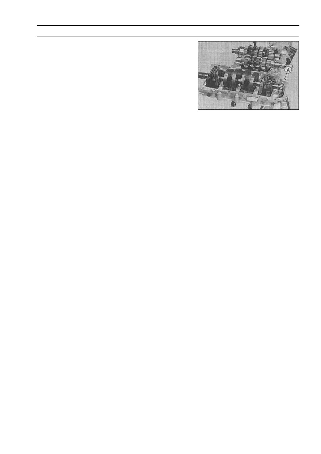
Remove the camshaft chain [A] from the crankshaft
•
sprocket.
4-16 ENGINE TOP END
Cylinder Head
Cylinder Compression Measurement
NOTE
○Use the battery which is fully charged.
Warm up the engine thoroughly.
•
Stop the engine.
•
Remove:
•
Seats (see Frame chapter)
Fuel Tank (see Fuel System chapter)
Air Cleaner Housing (see Fuel System chapter)
Stick Coils
Spark Plugs
Special Tool - Spark Plug Wrench, Hex 16: 57001-1262
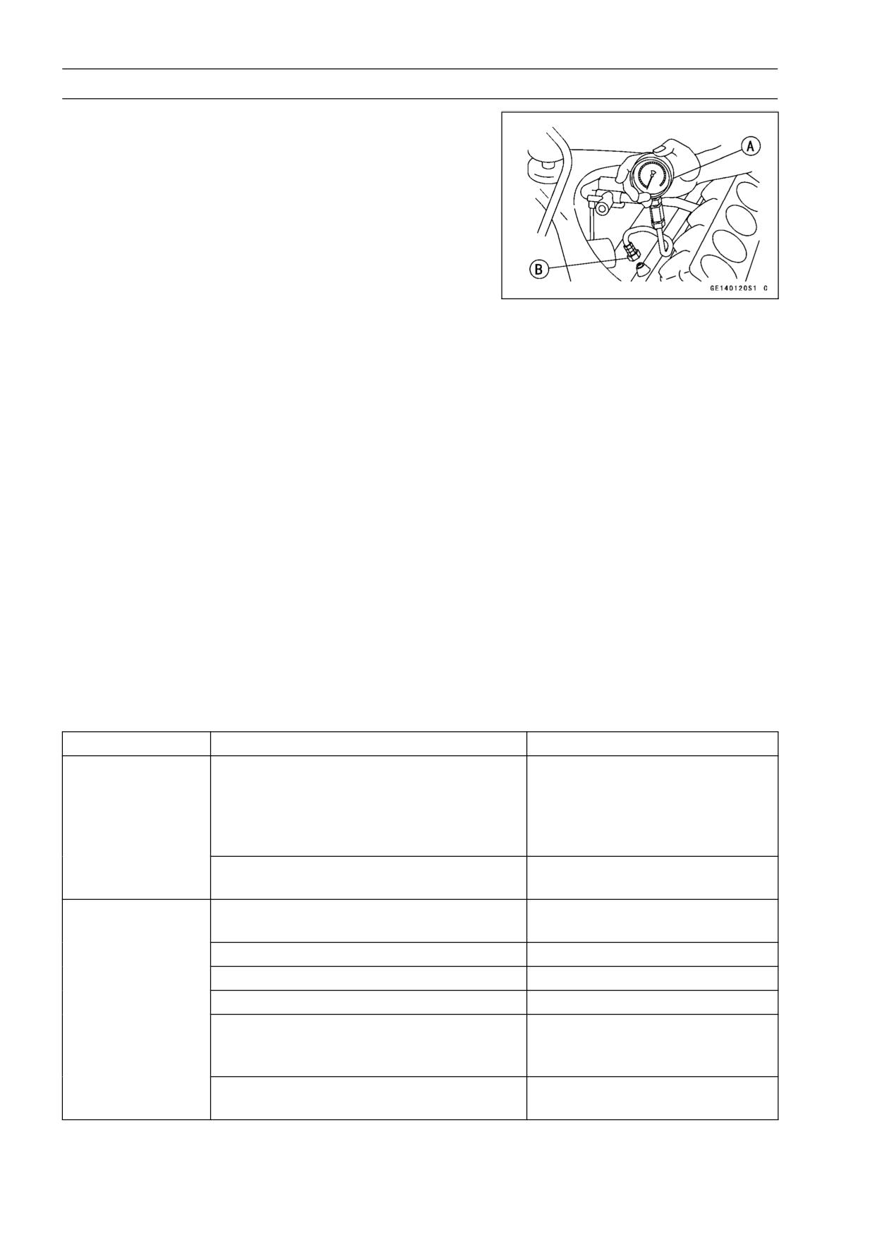
Attach the compression gauge [A] and adapter [B] firmly
•
into the spark plug hole.
○Using the starter motor, turn the engine over with the throt-
tle fully open until the compression gauge stops rising; the
compression is the highest reading obtainable.
Special Tool - Compression Gauge, 20 kgf/cm²: 57001-221
Compression Gauge Adapter, M10 × 1.0:
57001-1317
Cylinder Compression
Usable Range:
950 ∼ 1450 kPa (9.7 ∼ 14.8 kgf/cm², 138
∼ 210 psi) @350 r/min (rpm)
Repeat the measurement for the other cylinders.
•
Install the spark plugs and tighten them.
•
Torque - Spark Plugs: 13 N·m (1.3 kgf·m, 113 in·lb)
The following table should be consulted if the obtainable compression reading is not within the us-
able range.
Problem
Diagnosis
Remedy (Action)
Cylinder
Carbon accumulation on piston and in
Remove the carbon deposits
compression is
combustion chamber possibly due to
and replace damaged parts if
higher than usable
damaged valve stem oil seal and/or
necessary.
range
damaged piston oil rings (This may be
indicated by white exhaust smoke).
Incorrect cylinder head gasket thickness.
Replace the gasket with a
standard part.
Cylinder
Gas leakage around cylinder head
Replace damaged gasket and
compression is
check cylinder head warp.
lower than usable
Bad condition of valve seating
Repair if necessary.
range
Incorrect valve clearance.
Adjust the valve clearance.
Incorrect piston/cylinder clearance
Replace the piston and/or cylinder
Piston seizure.
Inspect the cylinder and
replace/repair the cylinder
and/or piston as necessary.
Bad condition of piston ring and/or piston
Replace the piston and/or the
ring grooves
piston rings.
ENGINE TOP END 4-17
Cylinder Head
Cylinder Head Removal
Drain the coolant (see Cooling System chapter).
•
Remove:
•
Cylinder Head Cover (see Cylinder Head Cover Re-
moval)
Camshaft Chain Tensioner (see Camshaft Chain Ten-
sioner Removal)
Camshafts (see Camshaft Removal)
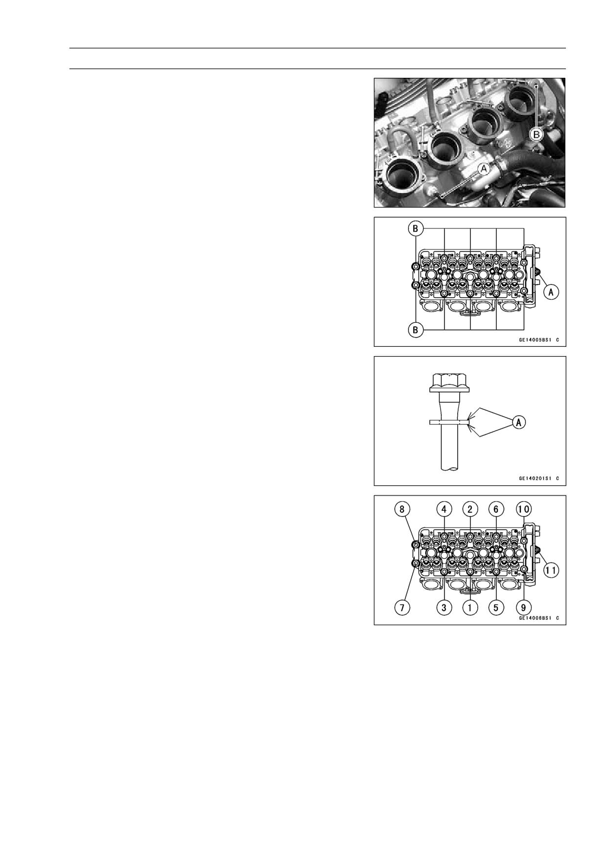
Water Temperature Sensor Lead Connector [A]
Oil Hose Banjo Bolt [B]
Remove the 6 mm cylinder head bolts [A], and then the
•
10 mm cylinder head bolts [B].
Take off the cylinder head.
•
Cylinder Head Installation
NOTE
○The camshaft cap is machined with the cylinder head,
so if a new cylinder head is installed, use the cap that
is supplied with the new head.
Install a new cylinder head gasket and knock pins.
•
Apply engine oil to both sides [A] of the cylinder head bolt
•
washers [B].
Tighten the 10 mm cylinder head bolts following the tight-
•
ening sequence [1 ∼ 10].
Torque - Cylinder Head Bolts (10mm)
First: 20 N·m (2.0 kgf·m, 14.5 ft·lb)
Final (Used Bolts): 49 N·m (5.0 kgf·m, 36 ft·lb)
Tighten the 6 mm cylinder head bolts [11].
•
Torque - Cylinder Head Bolts (6 mm): 12 N·m (1.2 kgf·m,
104 in·lb)
Tighten the oil hose banjo bolt.
•
Torque - Oil Hose Banjo Bolt: 25 N·m (2.5 kgf·m, 18.0 ft·lb)
4-18 ENGINE TOP END
Cylinder Head
Cylinder Head Warp Inspection
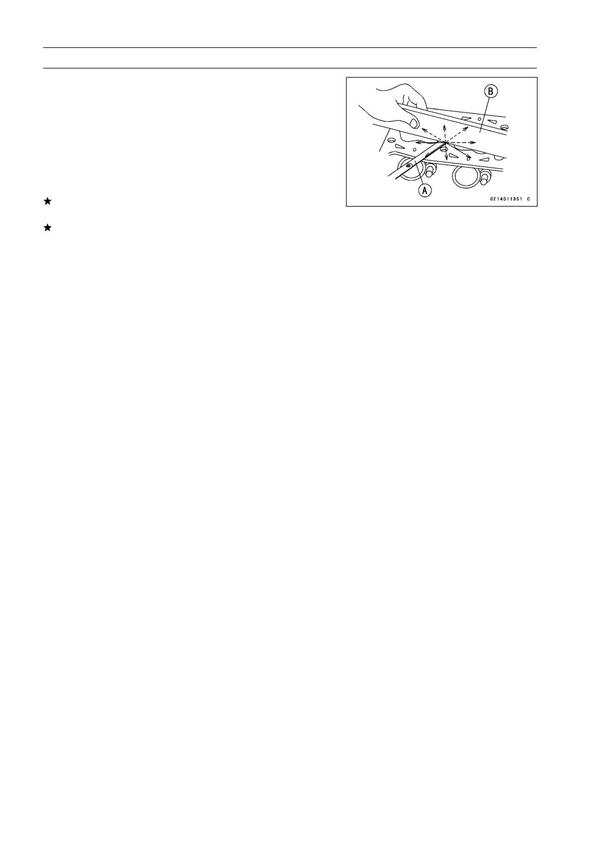
Lay a straightedge across the lower surface of the cylinder
•
head at several positions.
Use a thickness gauge [A] to measure the space between
•
the straightedge [B] and the head.
Cylinder Head Warp
Standard:
- - -
Service Limit:
0.05 mm (0.002 in.)
If the cylinder head is warped more than the service limit,
replace it.
If the cylinder head is warped less than the service limit,
repair the head by rubbing the lower surface on emery
paper secured to a surface plate (first No. 200, then No.
400).
ENGINE TOP END 4-19
Valves
Valve Clearance Inspection
NOTE
○Valve clearance must be checked and adjusted when
the engine is cold (at room temperature).
Remove:
•
Lower Fairings (see Frame chapter)
Crankshaft Sensor Cover
Cylinder Head Cover (see Cylinder Head Cover Re-
moval)
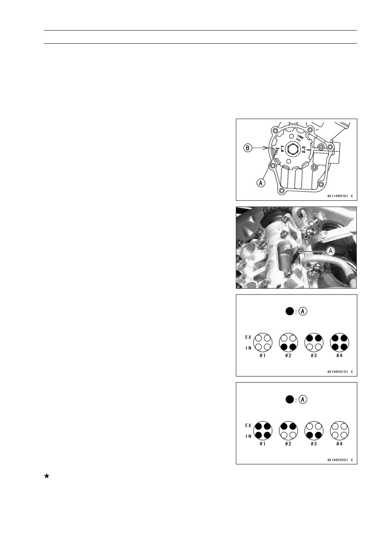
Position the crankshaft at 1,4 piston TDC.
•
TDC Mark [A] for #1, 4 Pistons
Timing Mark [B]
Using a thickness gauge [A], measure the valve clearance
•
between the cam and the valve lifter.
Valve Clearance
Standard:
IN
0.11∼ 0.19 mm (0.0043 ∼ 0.0075 in.)
EX
0.22 ∼ 0.31 mm (0.0087 ∼ 0.0122 in.)
○When positioning #4 piston TDC at the end of the
compression stroke:
Inlet valve clearance of #2 and #4 cylinders
Exhaust valve clearance of #3 and #4 cylinders
Measuring Valve [A]
○When positioning #1 piston TDC at the end of the
compression stroke:
Inlet valve clearance of #1 and #3 cylinders
Exhaust valve clearance of #1 and #2 cylinders
Measuring Valve [A]
If the valve clearance is not within the specified range,
first record the clearance, and then adjust it.
4-20 ENGINE TOP END
Valves
Valve Clearance Adjustment
To change the valve clearance, remove the camshaft
•
chain tensioner, camshafts and valve lifters. Replace the
shim with one of a different thickness.
NOTE
○Mark and record the valve lifter and shim locations so
they can be reinstalled in their original positions.
○If there is no clearance, select a shim which is several
sizes smaller and then measure the clearance.
To select a new shim which brings the valve clearance
•
within the specified range, refer to the Valve Clearance
Adjustment Charts.
Apply a thin coat of molybdenum disulfide grease to the
•
valve lifters.
Install the camshafts. Be sure to time the camshafts prop-
•
erly (see Camshaft Installation).
Remeasure any valve clearance that was adjusted.
•
Readjust if necessary.
CAUTION
Do not put shim stock under the shim. This may
cause the shim to pop out at high rpm, causing ex-
tensive engine damage.
Do not grind the shim. This may cause it to fracture,
causing extensive engine damage.
ENGINE TOP END 4-21
Valves
VALVE CLEARANCE ADJUSTMENT CHART INLET VALVE
1. Measure the clearance (when engine is cold).
2. Check present shim size.
3. Match clearance in vertical column with present shim
size in horizontal column.
4. Install the shim specified where the lines intersect. This
shim will give the proper clearance.
Example:
Present shim is 3.05 mm (0.120 in.).
Measured clearance is 0.35 mm (0.014 in.).
Replace 3.05 mm (0.120 in.) shim with 3.25
mm (0.128 in.) shim.
5. Remeasure the valve clearance and readjust if neces-
sary.
4-22 ENGINE TOP END
Valves
VALVE CLEARANCE ADJUSTMENT CHART EXHAUST VALVE
1. Measure the clearance (when engine is cold).
2. Check present shim size.
3. Match clearance in vertical column with present shim
size in horizontal column.
4. Install the shim specified where the lines intersect. This
shim will give the proper clearance.
Example:
Present shim is 3.10 mm (0.122 in.).
Measured clearance is 0.40 mm (0.016 in.).
Replace 3.10 mm (0.122 in.) shim with 3.2
mm (0.126 in.) shim.
5. Remeasure the valve clearance and readjust if neces-
sary.
ENGINE TOP END 4-23
Valves
Valve Removal
Remove the cylinder head (see Cylinder Head Removal).
•
Remove the valve lifter and shim.
•
○Mark and record the valve lifter and shim locations so they
can be installed in their original positions.
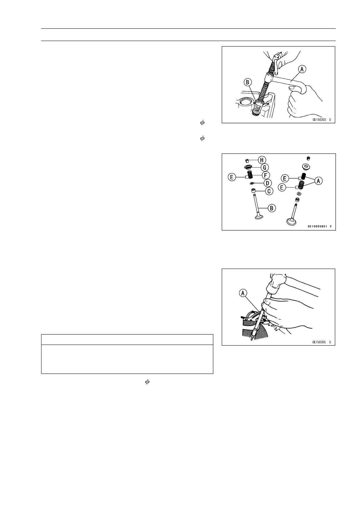
Using the valve spring compressor assembly, remove the
•
valve.
Special Tools - Valve Spring Compressor Assembly: 57001
-241 [A]
Valve Spring Compressor Adapter,
22:
57001-1202 [B]
Valve Spring Compressor Adapter,
20:
57001-1154
Valve Installation
Replace the oil seal with a new one.
•
Apply a thin coat of molybdenum disulfide grease to the
•
valve stem before valve installation.
Install the springs so that the closed coil end faces down-
•
wards.
[B] Valve Stem
[C] Oil Seal
[D] Spring Seat
[E] Closed Coil End
[F] Exhaust Valve Springs
[G] Retainer
[H] Split Keepers
○Dual springs [A] are used for the inlet valve.
Valve Guide Removal
Remove:
•
Valve (see Valve Removal)
Oil Seal
Spring Seat
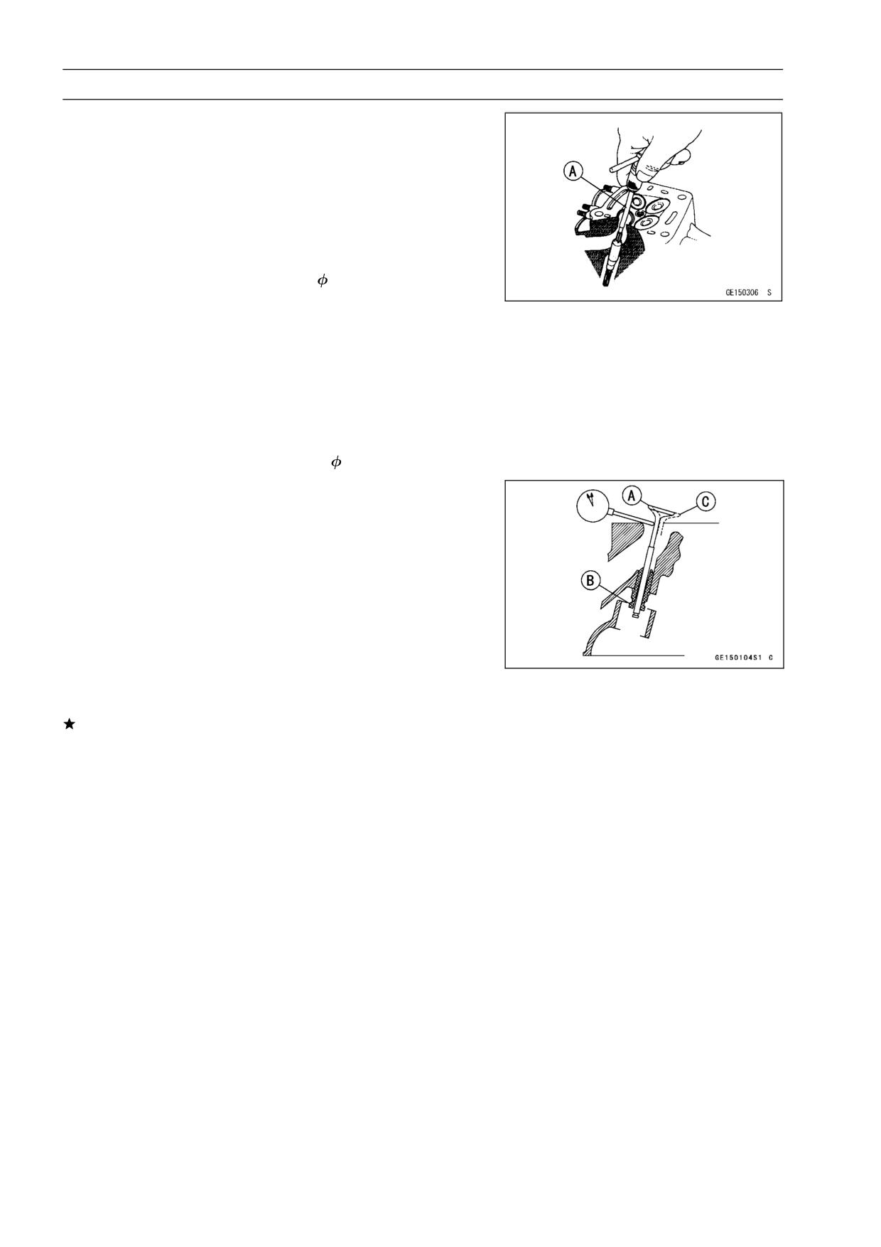
Heat the area around the valve guide to 120 ∼ 150°C (248
•
∼ 302 °F), and hammer lightly on the valve guide arbor [A]
to remove the guide from the top of the head.
CAUTION
Do not heat the cylinder head with a torch. This will
warp the cylinder head. Soak the cylinder head in
oil and heat the oil.
Special Tool - Valve Guide Arbor,
4: 57001-1273
4-24 ENGINE TOP END
Valves
Valve Guide Installation
Apply oil to the valve guide outer surface before installa-
•
tion.
Heat the area around the valve guide hole to about 120 ∼
•
150 °C (248 ∼ 302 °F).
Drive the valve guide in from the top of the head using the
•
valve guide arbor. The flange stops the guide from going
in too far.
Special Tool - Valve Guide Arbor,
4: 57001-1273
Wait until the cylinder head cools down and then ream the
•
valve guide with the valve guide reamer [A] even if the old
guide is reused.
○Turn the reamer in a clockwise direction until the reamer
turns freely in the guide. Never turn the reamer counter-
clockwise or it will be dulled.
○Once the guides are reamed they must be cleaned thor-
oughly.
Special Tool - Valve Guide Reamer,
4: 57001-1274
Valve-to-Guide Clearance Measurement (Wobble
Method)
If a small bore gauge is not available, inspect the valve
guide wear by measuring the valve to valve guide clearance
with the wobble method as indicated below.
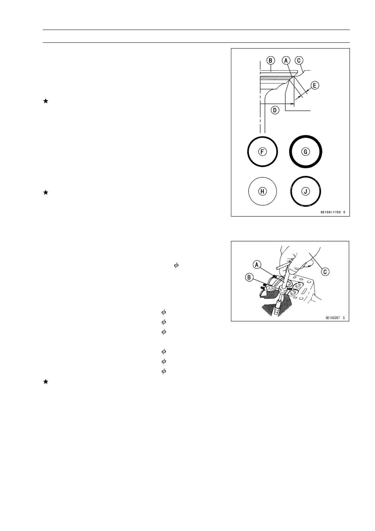
Insert a new valve [A] into the guide [B] and set a dial
•
gauge against the stem perpendicular to it as close as
possible to the cylinder head mating surface.
Move the stem back and forth [C] to measure valve/valve
•
guide clearance.
Repeat the measurement in a direction at a right angle to
•
the first.
If the reading exceeds the service limit, replace the guide.
NOTE
○The reading is not actual valve/valve guide clearance
because the measuring point is above the guide.
Valve/Valve Guide Clearance (Wobble Method)
Standard:
Inlet
0.03 ∼ 0.12 mm (0.0012 ∼ 0.0047 in.)
Exhaust
0.10 ∼ 0.18 mm (0.004 ∼ 0.007 in.)
Service Limit:
Inlet
0.29 mm (0.011 in.)
Exhaust
0.35 mm (0.014 in.)
ENGINE TOP END 4-25
Valves
Valve Seat Inspection
Remove the valve (see Valve Removal).
•
Check the valve seating surface [A] between the valve [B]
•
and valve seat [C].
○Measure the outside diameter [D] of the seating pattern
on the valve seat.
If the outside diameter is too large or too small, repair the
seat (see Seat Repair).
Valve Seating Surface Outside Diameter
Standard:
Inlet
26.4 ∼ 26.6 mm (1.039 ∼ 1.047 in.)
Exhaust
22.1 ∼ 22.3 mm (0.870 ∼ 0.878 in.)
○Measure the seat width [E] of the portion where there is
no build-up carbon (white portion) of the valve seat with a
vernier caliper.
Good [F]
If the width is too wide [G], too narrow [H] or uneven [J],
repair the seat (see Valve Seat Repair).
Valve Seating Surface Width
Standard:
Inlet, Exhaust
0.5 ∼ 1.0 mm (0.02 ∼ 0.04 in.)
Valve Seat Repair
Repair the valve seat with the valve seat cutters [A].
•
Special Tool - Valve Seat Cutter Holder,
4:
57001-1275
[B]
Valve Seat Cutter Holder Bar: 57001-1128
[C]
[For Inlet Valve Seat]
Valve Seat Cutter, 45° -
27.5: 57001-1114
Valve Seat Cutter, 32° -
28: 57001-1119
Valve Seat Cutter, 60° -
30: 57001-1123
[For Exhaust Valve Seat]
Valve Seat Cutter, 45° -
32: 57001-1115
Valve Seat Cutter, 32° -
30: 57001-1120
Valve Seat Cutter, 60° -
33: 57001-1334
If the manufacturer’s instructions are not available, use
the following procedure.
4-26 ENGINE TOP END
Valves
Seat Cutter Operation Care
1. This valve seat cutter is developed to grind the valve for
repair. Therefore the cutter must not be used for other
purposes than seat repair.
2. Do not drop or shock the valve seat cutter, or the dia-
mond particles may fall off.
3. Do not fail to apply engine oil to the valve seat cutter
before grinding the seat surface. Also wash off ground
particles sticking to the cutter with washing oil.
NOTE
○Do not use a wire brush to remove the metal particles
from the cutter. It will take off the diamond particles.
4. Setting the valve seat cutter holder in position, operate
the cutter in one hand. Do not apply too much force to
the diamond portion.
NOTE
○Prior to grinding, apply engine oil to the cutter and dur-
ing the operation, wash off any ground particles sticking
to the cutter with washing oil.
5. After use, wash it with washing oil and apply thin layer
of engine oil before storing.
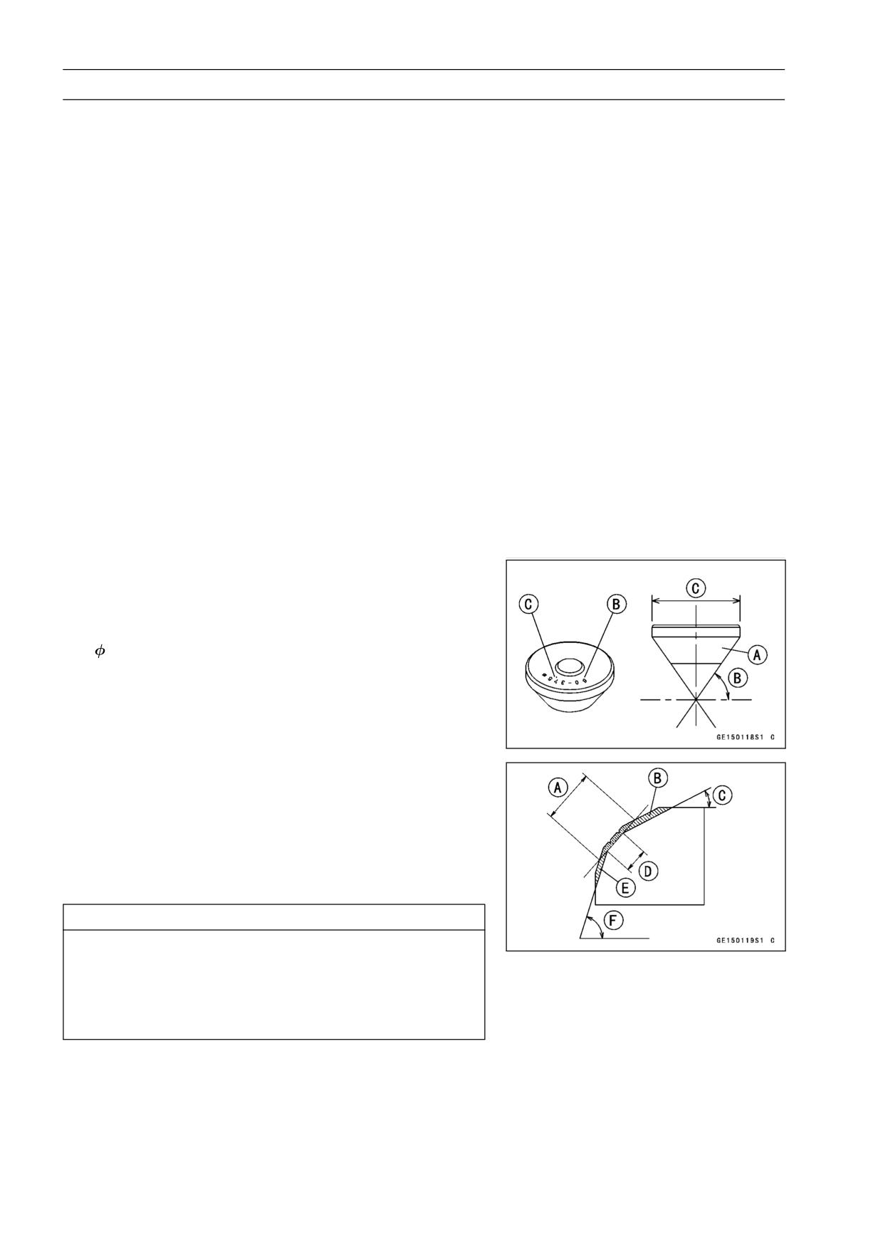
Marks Stamped on the Cutter
The marks stamped on the back of the cutter [A] represent
the following.
60°
Cutter angle [B]
37.5
....................... Outer diameter of cutter [C]
Operating Procedures
Clean the seat area carefully.
•
Coat the seat with machinist’s dye.
•
Fit a 45° cutter into the holder and slide it into the valve
•
guide.
Press down lightly on the handle and turn it right or left.
•
Grind the seating surface only until it is smooth.
CAUTION
Do not grind the seat too much. Overgrinding will
reduce valve clearance by sinking the valve into the
head. If the valve sinks too far into the head, it will
be impossible to adjust the clearance, and the cylin-
der head must be replaced.
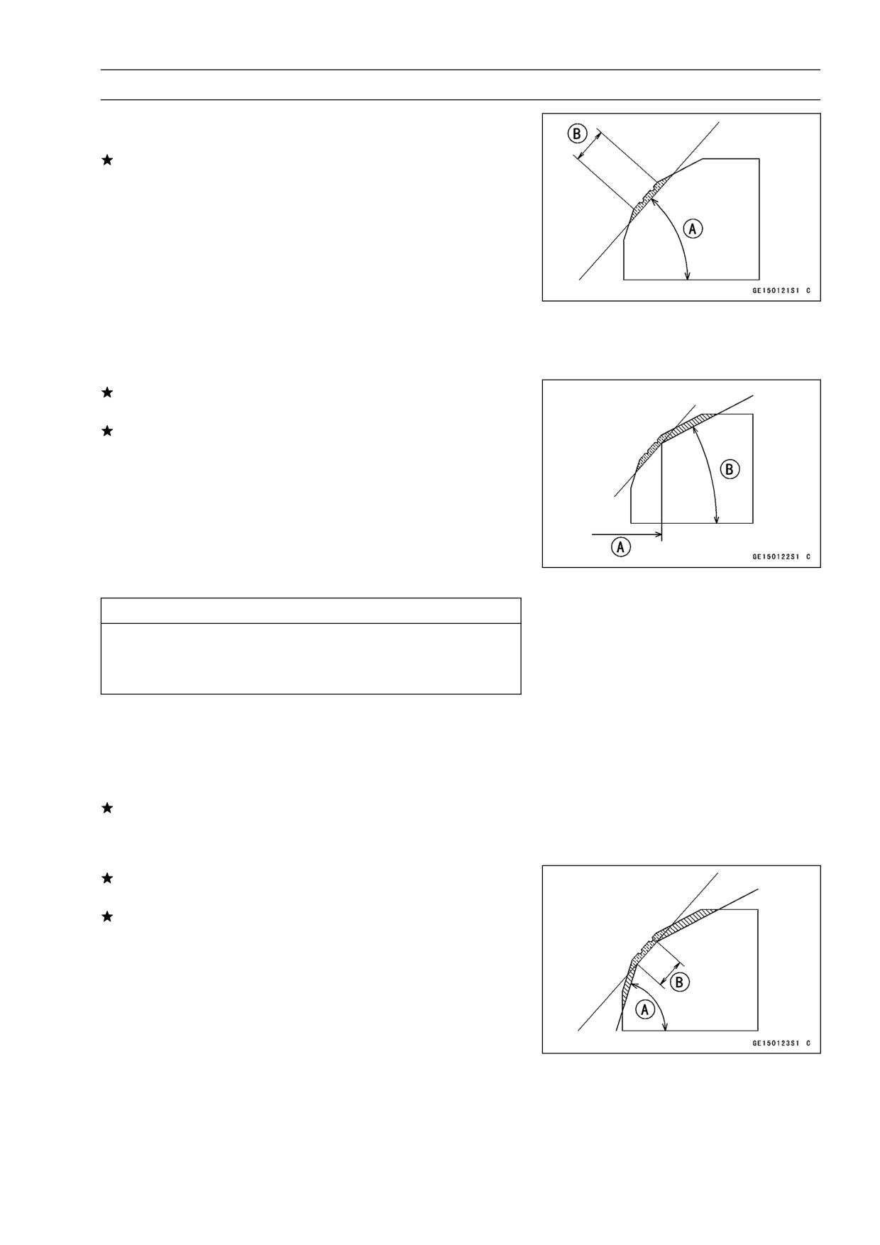
Widened Width [A] of engagement by machining with
45° cutter
Ground Volume [B] by 32° cutter
32° [C]
Correct Width [D]
Ground Volume [E] by 60° cutter
60° [F]
ENGINE TOP END 4-27
Valves
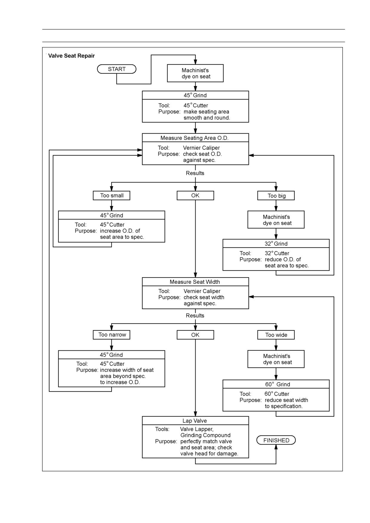
Measure the outside diameter of the seating surface with
•
a vernier caliper.
If the outside diameter of the seating surface is too small,
repeat the 45° grind [A] until the diameter is within the
specified range.
Original Seating Surface [B]
NOTE
○Remove all pittings of flaws from 45° ground surface.
○After grinding with 45° cutter, apply thin coat of machin-
ist’s dye to seating surface. This makes seating surface
distinct and 32° and 60° grinding operation easier.
○When the valve guide is replaced, be sure to grind with
45° cutter for centering and good contact.
If the outside diameter of the seating surface is too large,
make the 32° grind described below.
If the outside diameter [A] of the seating surface is within
the specified range, measure the seat width as described
below.
Grind the seat at a 32° angle [B] until the seat outside
•
diameter is within the specified range.
○To make the 32° grind, fit a 32° cutter into the holder, and
slide it into the valve guide.
○Turn the holder one turn at a time while pressing down
very lightly. Check the seat after each turn.
CAUTION
The
32° cutter removes material very quickly.
Check the seat outside diameter frequently to pre-
vent overgrinding.
○After making the 32° grind, return to the seat outside di-
ameter measurement step above.
To measure the seat width, use a vernier caliper to mea-
•
sure the width of the 45° angle portion of the seat at sev-
eral places around the seat.
If the seat width is too narrow, repeat the 45° grind until
the seat is slightly too wide, and then return to the seat
outside diameter measurement step above.
If the seat width is too wide, make the 60° [A] grind de-
scribed below.
If the seat width is within the specified range, lap the valve
to the seat as described below.
Grind the seat at a 60° angle until the seat width is within
•
the specified range.
○To make the 60° grind, fit 60° cutter into the holder, and
slide it into the valve guide.
○Turn the holder, while pressing down lightly.
○After making the 60° grind, return to the seat width mea-
surement step above.
Correct Width [B]
4-28 ENGINE TOP END
Valves
Lap the valve to the seat, once the seat width and outside
•
diameter are within the ranges specified above.
○Put a little coarse grinding compound on the face of the
valve in a number of places around the valve head.
○Spin the valve against the seat until the grinding com-
pound produces a smooth, matched surface on both the
seat and the valve.
○Repeat the process with a fine grinding compound.
[A] Lapper
[B] Valve Seat
[C] Valve
The seating area should be marked about in the middle
•
of the valve face.
If the seat area is not in the right place on the valve, check
to be sure the valve is the correct part. If it is, it may have
been refaced too much; replace it.
Be sure to remove all grinding compound before assem-
•
bly.
When the engine is assembled, be sure to adjust the valve
•
clearance (see Valve Clearance Adjustment).
ENGINE TOP END 4-29
Valves
4-30 ENGINE TOP END
Cylinder, Pistons
Cylinder Removal
Remove:
•
Engine (see Engine Removal/Installation chapter)
Cylinder Head (see Cylinder Head Removal)
Water Hoses [A]
Rear Camshaft Chain Guide and Bolt
Remove the cylinder.
•
Cylinder Installation
NOTE
○If a new cylinder is used, use new piston ring.
Install the pins [A] and new cylinder gasket.
•
Apply engine oil to the cylinder bore.
•
Prepare two auxiliary head bolts with their head cut.
•
Install the two bolts [B] diagonally in the crankcase.
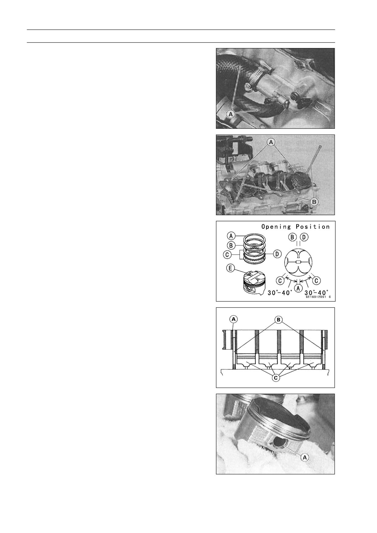
•
The piston ring openings must be positioned as shown in
•
the figure. The openings of the oil ring steel rails must be
about 30-40° of angle from the opening of the top ring.
[A] Top Ring
[B] Second Ring
[C] Oil Ring Steel Rails
[D] Oil Ring Expander
[E] Hollow
Position the crankshaft so that all the piston heads are
•
almost level.
Install the cylinder block [A].
•
Auxiliary Head Bolts [B]
Pistons [C]
Insert the piston rings with your thumbs.
•
Piston Removal
Remove the cylinder (see Cylinder Removal).
•
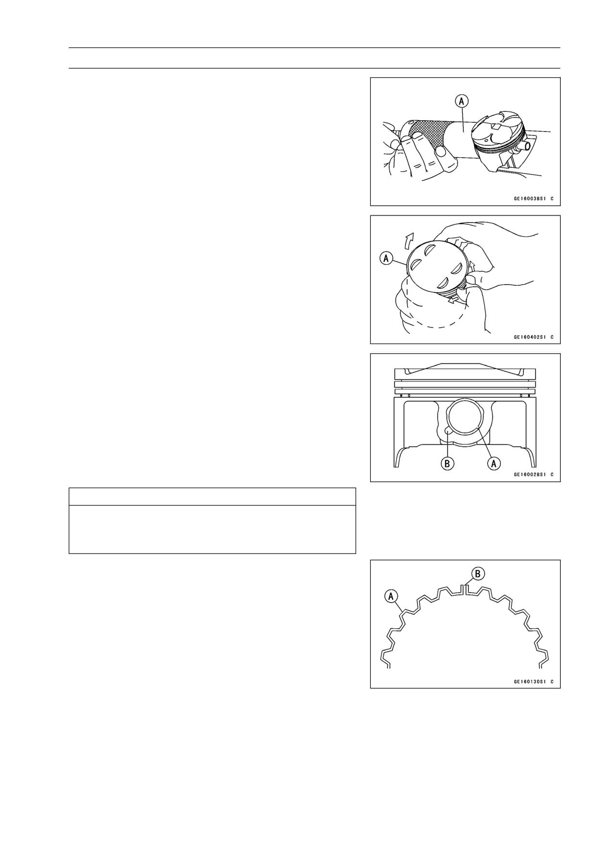
Place a clean cloth under the pistons and remove the pis-
•
ton pin snap ring [A] from the outside of each piston.
ENGINE TOP END 4-31
Cylinder, Pistons
Remove the piston pins.
•
Special Tool - Piston Pin Puller Assembly: 57001-910 [A]
Carefully spread the ring opening with your thumbs and
•
then push up on the opposite side of the ring [A] to remove
it.
Remove the 3-piece oil ring with your thumbs in the same
•
manner.
Piston Installation
NOTE
○If a new piston is used, use new piston ring.
Install the piston with its marking hollow facing forward.
•
Fit a new piston pin snap ring into the side of the piston
•
so that the ring opening [A] does not coincide with the slit
[B] of the piston pin hole.
○When installing the piston pin snap ring, compress it only
enough to install it and no more.
CAUTION
Do not reuse snap rings, as removal weakens and
deforms them.
They could fall out and score the cylinder wall.
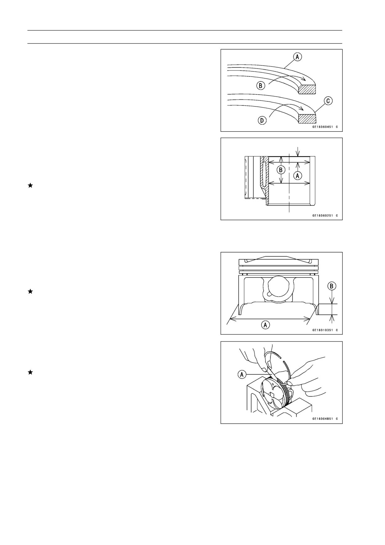
Install the oil ring expander [A] in the bottom piston ring
•
groove so the ends [B] butt together.
Install the oil ring steel rails, one above the expander and
•
one below it.
○Spread the rail with your thumbs, but only enough to fit
the rail over the piston.
○Release the rail into the bottom piston ring groove.
NOTE
○The oil ring rails have no “top” or “bottom”.
4-32 ENGINE TOP END
Cylinder, Pistons
Do not mix up the top and second ring.
•
Install the top ring [A] so that the "R" mark [B] faces up.
•
○Install the second ring [C] so that the "RN" mark [D] faces
up.
Cylinder Wear Inspection
Since there is a difference in cylinder wear in different di-
•
rections, take a side-to-side and a front-to-back measure-
ment at each of the two locations (total of four measure-
ments) shown in the figure.
If any of the cylinder inside diameter measurements ex-
ceeds the service limit, replace the cylinder.
[A] 10 mm (0.39 in.)
[B] 60 mm (2.36 in.)
Cylinder Inside Diameter
Standard:
65.960 ∼ 65.972 mm (2.5968 ∼ 2.5973 in.)
Service Limit: 66.06 mm (2.601 in.)
Piston Wear Inspection
Measure the outside diameter [A] of each piston 5 mm
•
(0.20 in.) [B] up from the bottom of the piston at a right
angle to the direction of the piston pin.
If the measurement is under service limit, replace the pis-
ton.
Piston Diameter
Standard:
65.935 ∼ 65.950 mm (2.5957 ∼ 2.5965 in.)
Service Limit: 65.78 mm (2.590 in.)
Piston Ring, Piston Ring Groove Wear Inspection
Check for uneven groove wear by inspecting the ring seat-
•
ing.
The rings should fit perfectly parallel to groove surfaces.
If not, replace the piston and all the piston rings.
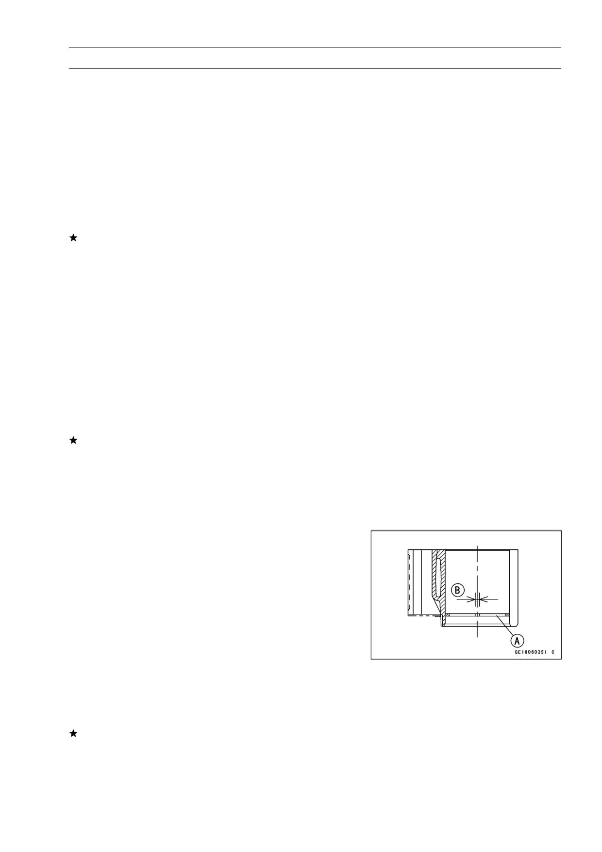
With the piston rings in their grooves, make several mea-
•
surements with a thickness gauge [A] to determine piston
ring/groove clearance.
Piston Ring/Groove Clearance
Standard:
Top
0.05 ∼ 0.09 mm (0.0020 ∼ 0.0035 in.)
Second
0.03 ∼ 0.07 mm (0.0012 ∼ 0.0028 in.)
Service Limit:
Top
0.19 mm (0.0075 in.)
Second
0.17 mm (0.0067 in.)
ENGINE TOP END 4-33
Cylinder, Pistons
Piston Ring Groove Width Inspection
Measure the piston ring groove width.
•
○Use a vernier caliper at several points around the piston.
Piston Ring/Groove Width
Standard:
Top
0.84 ∼ 0.86 mm (0.0331 ∼ 0.0339 in.)
Second
0.82 ∼ 0.84 mm (0.0323 ∼ 0.0331 in.)
Service Limit:
Top
0.94 mm (0.037 in.)
Second
0.92 mm (0.036 in.)
If the width of any of the two grooves is wider than the
service limit at any point, replace the piston.
Piston Ring Thickness Inspection
Measure the piston ring thickness.
•
○Use the micrometer to measure at several points around
the ring.
Piston Ring Thickness
Standard:
Top
0.77 ∼ 0.79 mm (0.0303 ∼ 0.0311 in.)
Second
0.77 ∼ 0.79 mm (0.0303 ∼ 0.0311 in.)
Service Limit:
Top
0.70 mm (0.028 in.)
Second
0.70 mm (0.028 in.)
If any of the measurements is less than the service limit
on either of the rings, replace all the rings.
NOTE
○When using new rings in a used piston, check for un-
even groove wear. The rings should fit perfectly parallel
to the groove sides. If not, replace the piston.
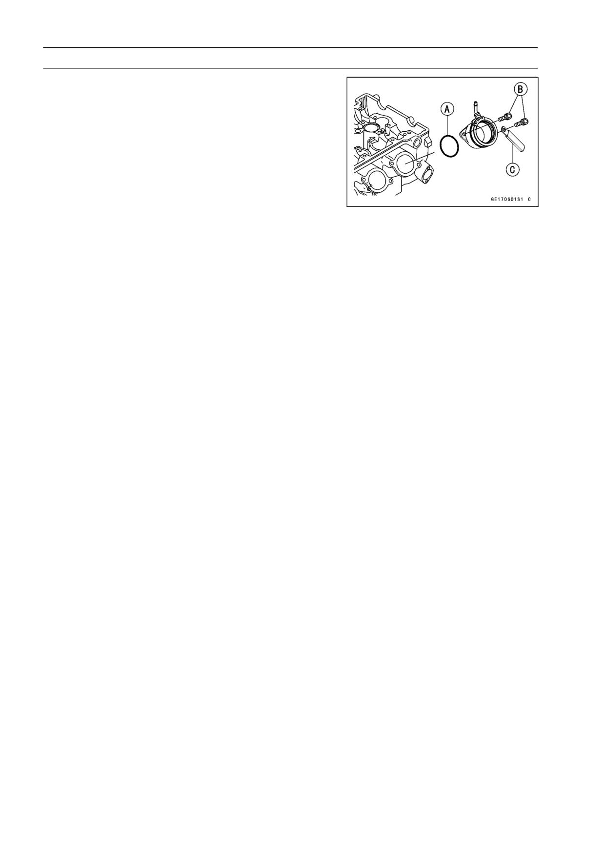
Piston Ring End Gap Inspection
Place the piston ring [A] inside the cylinder, using the pis-
•
ton to locate the ring squarely in place. Set it close to the
bottom of the cylinder, where cylinder wear is low.
Measure the gap [B] between the ends of the ring with a
•
thickness gauge.
Piston Ring End Gap
Standard:
Top
0.15 ∼ 0.3 mm (0.0059 ∼ 0.0118 in.)
Second
0.30 ∼ 0.45 mm (0.0118 ∼ 0.0177 in.)
Service Limit:
Top
0.6 mm (0.024 in.)
Second
0.8 mm (0.031 in.)
If the end gap of either ring is greater than the service
limit, replace all the rings.
4-34 ENGINE TOP END
Carburetor Holder
Carburetor Holder Installation
Be sure to install the O-rings [A].
•
Tighten the carburetor holder bolts [B].
•
Tighten the #1,3 right carburetor holder bolts with clamp
•
[C] (use of clamps for California Model only).
Torque - Carburetor Holder Bolts: 12 N·m (1.2 kgf·m, 104
in·lb)
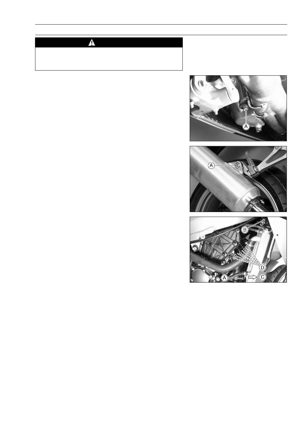
ENGINE TOP END 4-35
Muffler
WARNING
To avoid a serious burn, do not remove the mufflers
when the engine is still hot. Wait until the mufflers
cool down.
Muffler and Exhaust Pipe Removal
Remove:
•
Lower Fairings (see Frame chapter)
Exhaust Pipe Mounting Bolt [A]
Remove the muffler mounting nut [A].
•
Remove the radiator mount bolt [A].
•
Loosen the radiator bolts [B].
•
Move the bottom of the radiator toward the front [C], and
•
then tighten the radiator bolts [B].
Remove:
•
Exhaust Pipe Holder Nuts [D]
Pull the muffler mounting bolt and remove the muffler as-
•
sembly.
○When removing the exhaust pipe holder, don’t hit the ra-
diator.
Muffler and Exhaust Pipe Installation
Replace the exhaust pipe holder gaskets with new ones.
•
Thoroughly warm up the engine, wait until the engine
•
cools down, and retighten all the bolts and nuts.
Tighten the exhaust pipe holder nuts.
•
Tighten:
•
Torque - Exhaust Pipe Mounting Bolt: 34 N·m (3.5 kgf·m,
25 ft·lb)
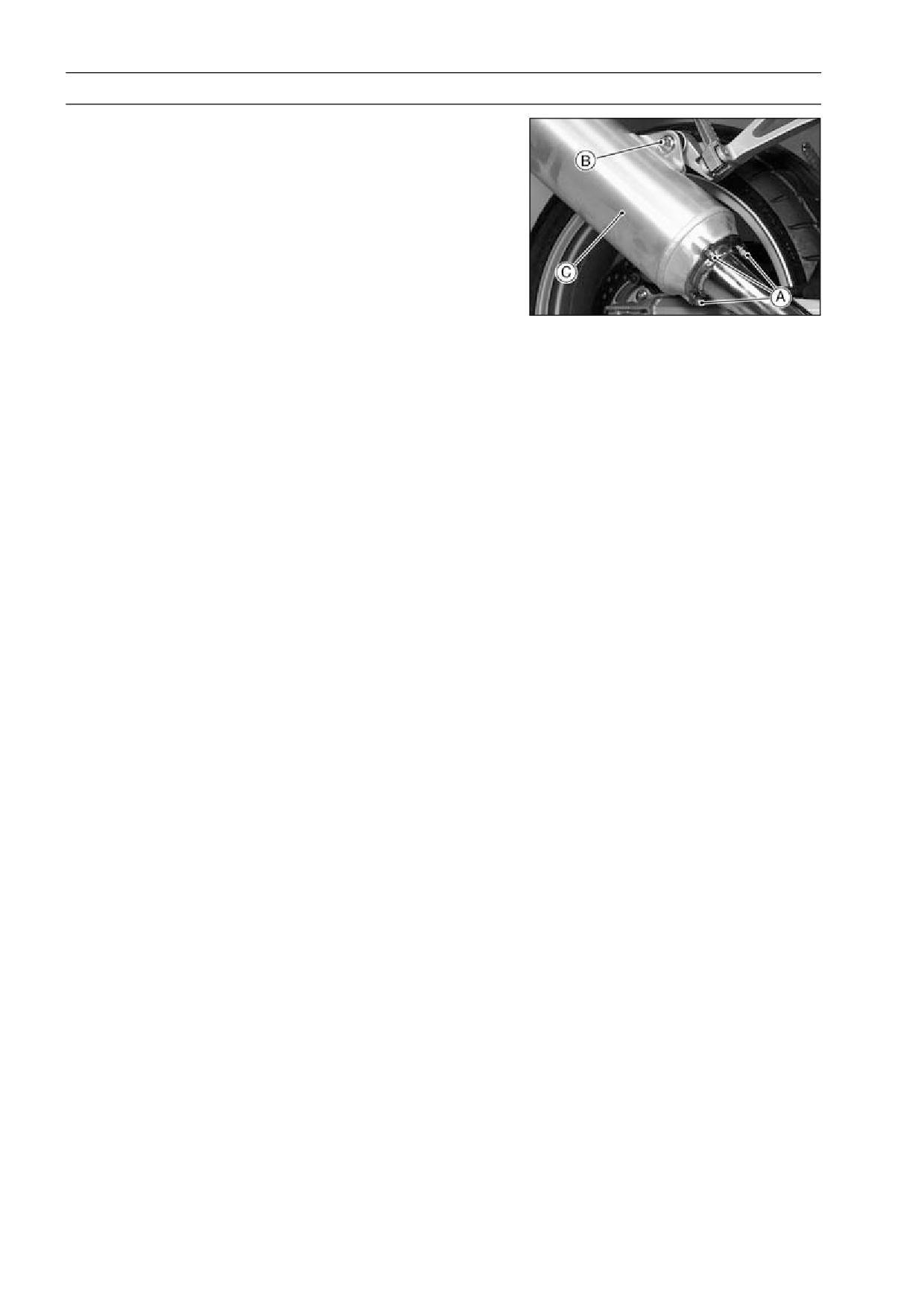
4-36 ENGINE TOP END
Muffler
Muffler Body Removal
Remove:
•
Exhaust Pipe Connecting Nuts [A]
Muffler Mounting Bolt, Nut [B] and Washer
Pull the muffler body [C] backward.
Muffler Body Installation
Replacing the muffler body gasket with new one.
•
Tighten:
•
Torque - Muffler Body and Exhaust Pipe Connecting Nuts:
45 N·m (4.5 kgf·m, 33 ft·lb)
Thoroughly warm up the engine, wait until the engine
•
cools down, and retighten all the bolts and nuts.
CLUTCH 5-1
Clutch
Table of Contents
Exploded View
5-2
Specifications
5-3
Clutch Lever and Cable
5-4
Clutch Lever Free Play Inspection
5-4
Clutch Lever Free Play Adjustment
5-4
5
Clutch Cable Removal
5-5
Clutch Cable Installation
5-5
Clutch Cable Lubrication
5-5
Clutch Lever Installation
5-5
Clutch Cover
5-6
Clutch Cover Removal
5-6
Clutch Cover Installation
5-6
Clutch Release Shaft Removal
5-6
Clutch Release Shaft Installation
5-6
Clutch
5-7
Clutch Removal
5-7
Clutch Installation
5-7
Clutch Plate Assembly Inspection
5-9
Clutch Plate Assembly Adjustment
5-10
Clutch Plate Wear, Damage Inspection
5-10
Clutch Plate Warp Inspection
5-10
Clutch Spring Free Length Measurement
5-11
5-2 CLUTCH
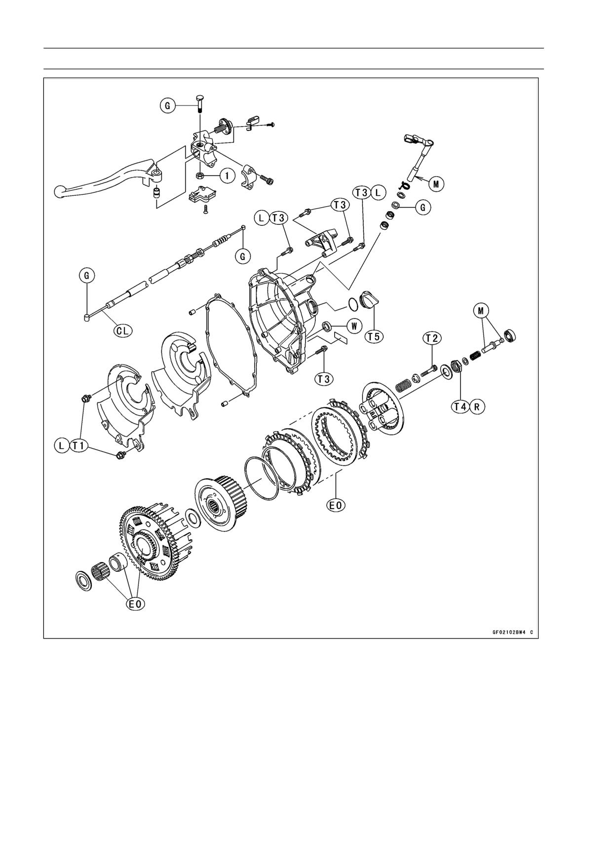
Exploded View
1. Clutch Lever Pivot Nut
T1: 5.9 N·m (0.60 kgf·m, 52 in·lb)
T2: 8.8 N·m (0.90 kgf·m, 78 in·lb)
T3: 12 N·m (1.2 kgf·m, 104 in·lb)
T4: 137 N·m (14 kgf·m, 101 ft·lb)
T5: 1.5 N·m (0.15 kgf·m, 13 in·lb) or Hand-Tight
CL: Apply cable lubricant.
EO: Apply engine oil.
G: Apply grease.
L: Apply a non-permanent locking agent.
M: Apply molybdenum disulfide grease.
R: Replacement Parts
W: Apply water.
CLUTCH 5-3
Specifications
Item
Standard
Service Limit
Clutch Lever Free Play
2 ∼ 3 mm (0.08 ∼ 0.12 in.)
- - -
Clutch
Friction Plate Thickness
2.72 ∼ 2.88 mm (0.107 ∼ 0.113 in.)
2.2 mm (0.087 in.)
Friction and Steel Plate Warp
0.2 mm (0.008 in.) or less
0.3 mm (0.012 in.)
Clutch Spring Free Length
82.1 mm (3.23 in.)
78.0 mm (3.07 in.)
Clutch Plate Assembly Length
37.7 ∼ 38.3 mm (1.48 ∼ 1.51 in.)
- - -
Special Tool - Clutch Holder: 57001-1243
Sealant - Kawasaki Bond (Silicone Sealant): 56019-120
5-4 CLUTCH
Clutch Lever and Cable
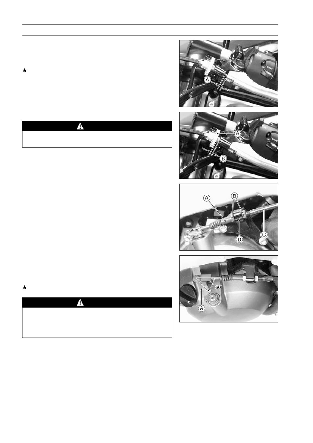
Clutch Lever Free Play Inspection
Pull the clutch lever just enough to take up the free play
•
[A].
Measure the gap between the lever and the lever holder.
•
If the gap is too wide, the clutch may not release fully. If
the gap is too narrow, the clutch may not engage fully. In
either case, adjust it.
Clutch Lever Free Play
Standard:
2 ∼ 3 mm (0.08 ∼ 0.12 in.)
Clutch Lever Free Play Adjustment
WARNING
To avoid a serious burn, never touch the engine or
exhaust pipe during clutch adjustment.
Turn the adjuster [A] so that 5 ∼ 6 mm (0.20 ∼ 0.24 in.) [B]
•
of threads are visible.
Slide the dust cover [A] at the clutch cable lower end out
•
of place.
Loosen both adjusting nuts [B] at the clutch cover as far
•
as they will go.
Pull the clutch outer cable [C] tight and tighten the adjust-
•
ing nuts against the bracket [D].
Slip the rubber dust cover back onto place.
•
Turn the adjuster at the clutch lever until the free play is
•
correct.
Push the release lever [A] toward the front of the motor-
•
cycle until it becomes hard to turn.
○At this time, the release lever should have the proper an-
gle shown.
If the angle is wrong, check the clutch and release parts
for wear.
WARNING
Be sure that the outer cable end at the clutch lever
is fully seated in the adjuster at the clutch lever, or
it could slip into place later, creating enough cable
play to prevent clutch disengagement.
After the adjustment, start the engine and check that the
•
clutch does not slip and that it releases properly.

CLUTCH 5-5
Clutch Lever and Cable
Clutch Cable Removal
Remove the right lower fairing (see frame chapter).
•
Slide the dust cover at the clutch cable lower end out of
•
place.
Loosen the nuts, and slide the lower end of the clutch
•
cable to give the cable plenty of play.
Screw in the adjuster.
•
Line up the slots [A] in the clutch lever, and adjuster [B],
•
and then free the cable from the lever.
Free the clutch inner cable tip from the clutch release
•
lever.
Push the release lever toward the front of the motorcycle
•
and tape the release lever to the clutch cover to prevent
the release shaft from falling out.
Pull the clutch cable out of the frame.
•
Clutch Cable Installation
Run the clutch cable correctly (see General Information
•
chapter).
Adjust the clutch cable (see Lever Free Play Adjustment).
•
Clutch Cable Lubrication
Whenever the clutch cable is removed, lubricate the
clutch cable as follows.
Apply a thin coating of grease to the cable upper and
•
lower ends.
Lubricate the cable with a penetrating rust inhibitor.
•
Clutch Lever Installation
Install the clutch lever so that the mating surface [A] of
•
the switch housing is aligned with the mating surface [B]
of the clutch lever clamp.
5-6 CLUTCH
Clutch Cover
Clutch Cover Removal
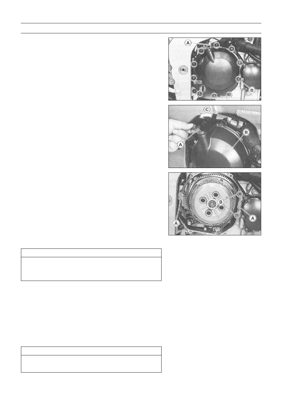
Remove:
•
Engine Oil (drain, see Engine Lubrication System chap-
ter)
Right Lower Fairing (see Frame chapter)
Oil Hose
Clutch Cable Lower End [A]
Clutch Cover Mounting Bolts [B]
Turn the release lever [A] toward the rear as shown, and
•
remove the clutch cover [B].
[C] about 90°
Clutch Cover Installation
Apply silicone sealant to the area [A] where the mating
•
surface of the crankcase touches the clutch cover gasket.
Sealant - Kawasaki Bond (Silicone Sealant): 56019-120
Replace the cover gasket with a new one.
•
Apply a non-permanent locking agent to the threads of
•
the two clutch cover bolts [B].
Tighten the cover bolts.
•
Torque - Clutch Cover Bolts: 12 N·m (1.2 kgf·m, 104 in·lb)
Clutch Release Shaft Removal
CAUTION
Do not remove the clutch release lever and shaft
assembly unless it is absolutely necessary. If re-
moved, the oil seal replacement may be required.
Remove the clutch cover (see Clutch Cover Removal).
•
Pull the lever and shaft assembly out of the clutch cover.
•
Clutch Release Shaft Installation
Apply high-temperature grease to the oil seal lips on the
•
upper ridge of the clutch cover.
Apply molybdenum disulfide grease to the clutch release
•
shaft.
Insert the clutch release shaft straight into the upper hole
•
of the clutch cover.
CAUTION
When inserting the clutch release shaft, be careful
not to remove the spring of the oil seal.
CLUTCH 5-7
Clutch
Clutch Removal
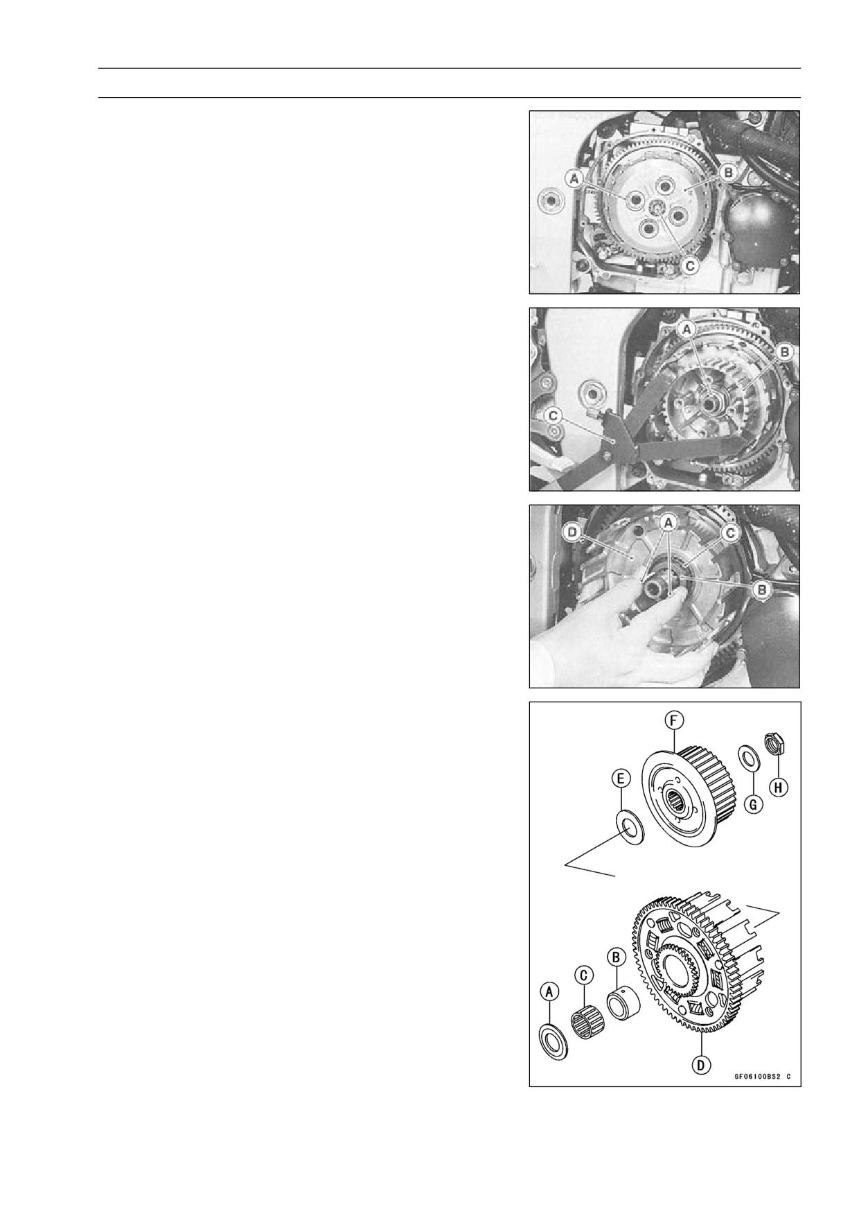
Remove:
•
Engine Oil (drain, see Engine Lubrication System chap-
ter)
Right Lower Fairing (see Frame chapter)
Clutch Cover (see Clutch Cover Removal)
Clutch Spring Bolts [A]
Clutch Springs
Clutch Spring Plate [B] (with thrust bearing and pusher
[C], spring and washer)
Friction Plates, Steel Plates
Spring, Spring Seat
Clutch Hub Nut [A]
○Holding the clutch hub [B], remove the nut.
Special Tool - Clutch Holder: 57001-1243 [C]
Remove:
•
Clutch Hub
Using the two 4 mm screws [A], pull out the sleeve [B],
•
needle bearing [C] and clutch housing [D].
Remove the spacer.
•
Clutch Installation
Inspect the clutch plate assembly length (see Clutch Plate
•
Assembly Inspection).
Install the following parts on the drive shaft.
•
[A] Spacer
[B] Sleeve
[C] Needle Bearing
[D] Clutch Housing
[E] Spacer
[F] Clutch Hub
[G] Washer
[H] Nut
5-8 CLUTCH
Clutch
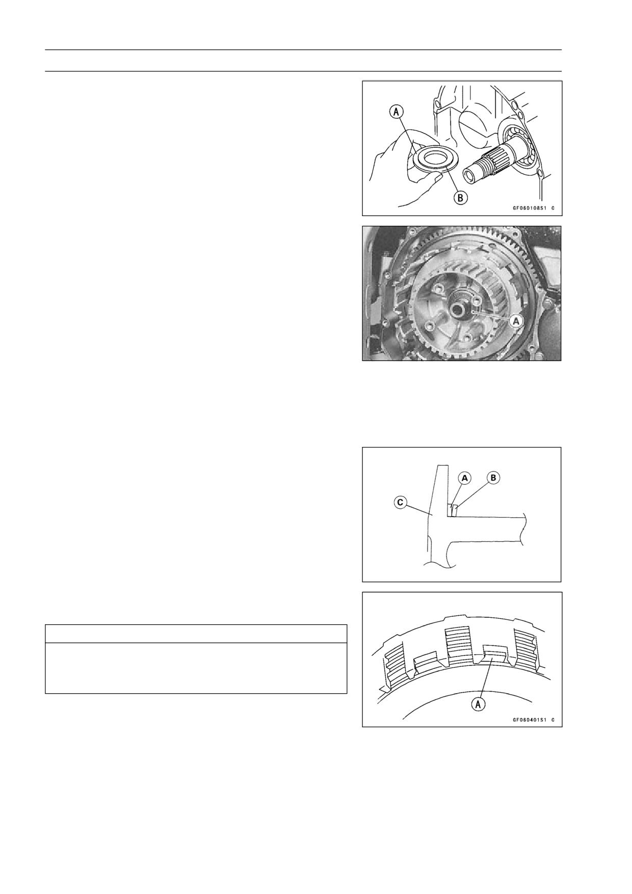
○Install the spacer [A] so that the stepped side [B] faces
inward.
○Install the washer [A] so that the OUT SIDE mark faces
outward.
○Replace the clutch hub nut with a new one.
○Holding the clutch hub, tighten the clutch hub nut.
Special Tool - Clutch Holder: 57001-1243
Torque - Clutch Hub Nut: 137 N·m (14 kgf·m, 101 ft·lb)
Install the spring seat [A] and spring [B] as shown.
•
[C] Clutch Hub
Install the friction plates and steel plates, starting with a
•
friction plate and alternating them.
CAUTION
If new dry friction plates and steel plates are in-
stalled, apply engine oil to the surfaces of each
plate to avoid clutch plate seizure.
○Install the last friction plate [A] fitting the tangs in the
grooves in the housing as shown.
CLUTCH 5-9
Clutch
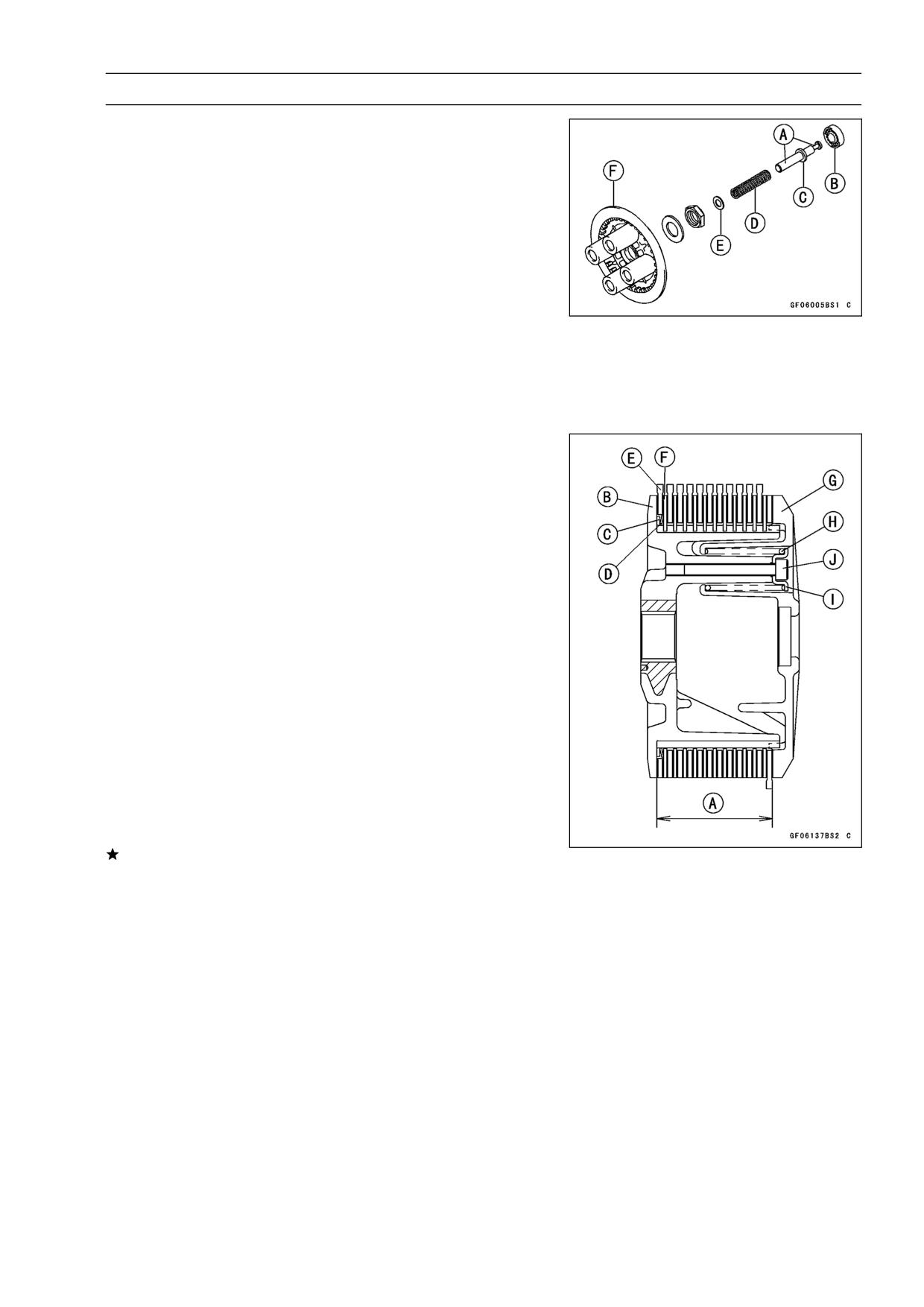
Apply molybdenum disulfide grease to the pusher end
•
[A] and install the bearing [B], pusher [C] spring [D] and
washer [E] in the clutch spring plate [F].
Install the clutch spring plate and spring, and tighten the
•
clutch spring bolts.
Torque - Clutch Spring Bolts: 8.8 N·m (0.90 kgf·m, 78 in·lb)
Install the clutch cover (see Clutch Cover Installation).
•
Clutch Plate Assembly Inspection
Inspect the friction plate thickness (see Clutch Plate,
•
Wear, Damage Inspection).
Measure the length [A] of the clutch plate assembly as
•
shown.
○Assemble:
Clutch Hub [B]
Spring Seat [C]
Spring [D]
Friction Plate [E]
Steel Plte [F]
Spring Plate [G]
Springs [H]
Spring Holders [I]
Spring Bolts [J]
○Tighten:
Torque - Clutch Spring Bolts: 8.8 N·m (0.90 kgf·m, 78 in·lb)
Clutch Plate Assembly
Standard:
37.7 ∼ 38.3 mm (1.48 ∼ 1.51 in.)
If the length is not within the specified range, adjust the
length (see Clutch Plate Assembly Adjustment).
5-10 CLUTCH
Clutch
Clutch Plate Assembly Adjustment
Inspect the clutch plate assembly length, and then re-
•
place the steel plate(s) which brings the length within the
specified range.
○Remove:
Spring Bolts
Spring Holders
Springs
Spring Plate
Replace the following steel plate(s).
•
Part No.
Thickness
13089-1126
1.4 mm (0.055 in.)
13089-013
1.6 mm (0.063 in.) (STD)
13089-1073
2.0 mm (0.08 in.)
NOTE
○Do not use the steel plate of 1.4 mm and 2.0 mm thick-
ness at the same time.
Install the removed parts, and inspect the clutch plate as-
•
sembly length.
Tighten:
•
Torque - Clutch Spring Bolts: 8.8 N·m (0.90 kgf·m, 78 in·lb)
Clutch Plate Wear, Damage Inspection
Visually inspect the friction and steel plates for signs of
•
seizure, overheating (discoloration), or uneven wear.
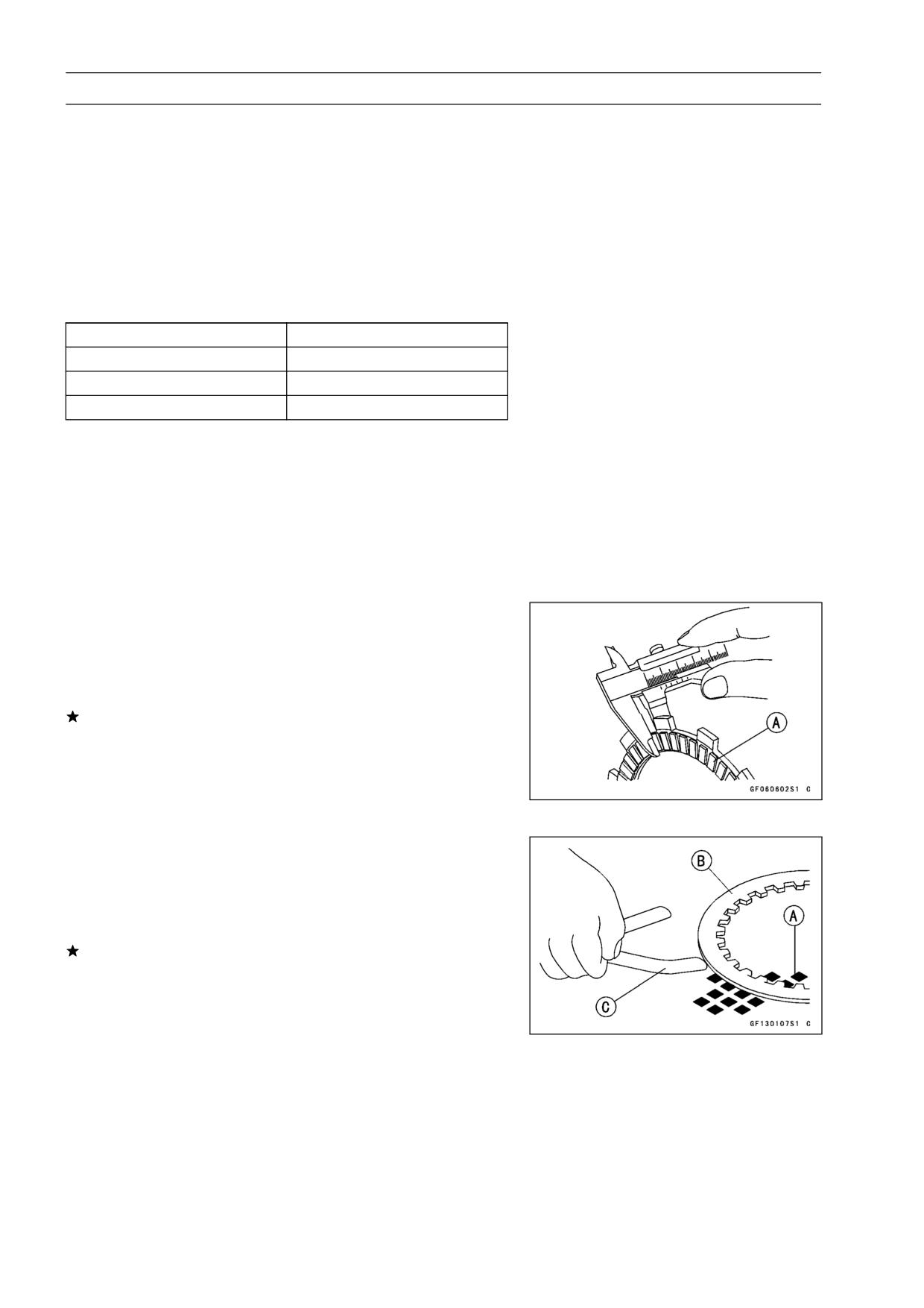
Measure the thickness of each friction plate [A] at several
•
points.
If any plates show signs of damage, or if they have worn
past the service limit, replace them with new ones.
Friction Plate Thickness
Standard:
2.72 ∼ 2.88 mm (0.107 ∼ 0.113 in.)
Service Limit:
2.2 mm (0.087 in.)
Clutch Plate Warp Inspection
Place each friction plate or steel plate on a surface plate
•
and measure the gap between the surface plate [A] and
each friction plate or steel plate [B] with a thickness gauge
[C]. The gap is the amount of friction or steel plate warp.
If any plate is warped over the service limit, replace it with
a new one.
Friction and Steel Plate Warp
Standard:
0.2 mm (0.008 in.) or less
Service Limit:
0.3 mm (0.012 in.)
CLUTCH 5-11
Clutch
Clutch Spring Free Length Measurement
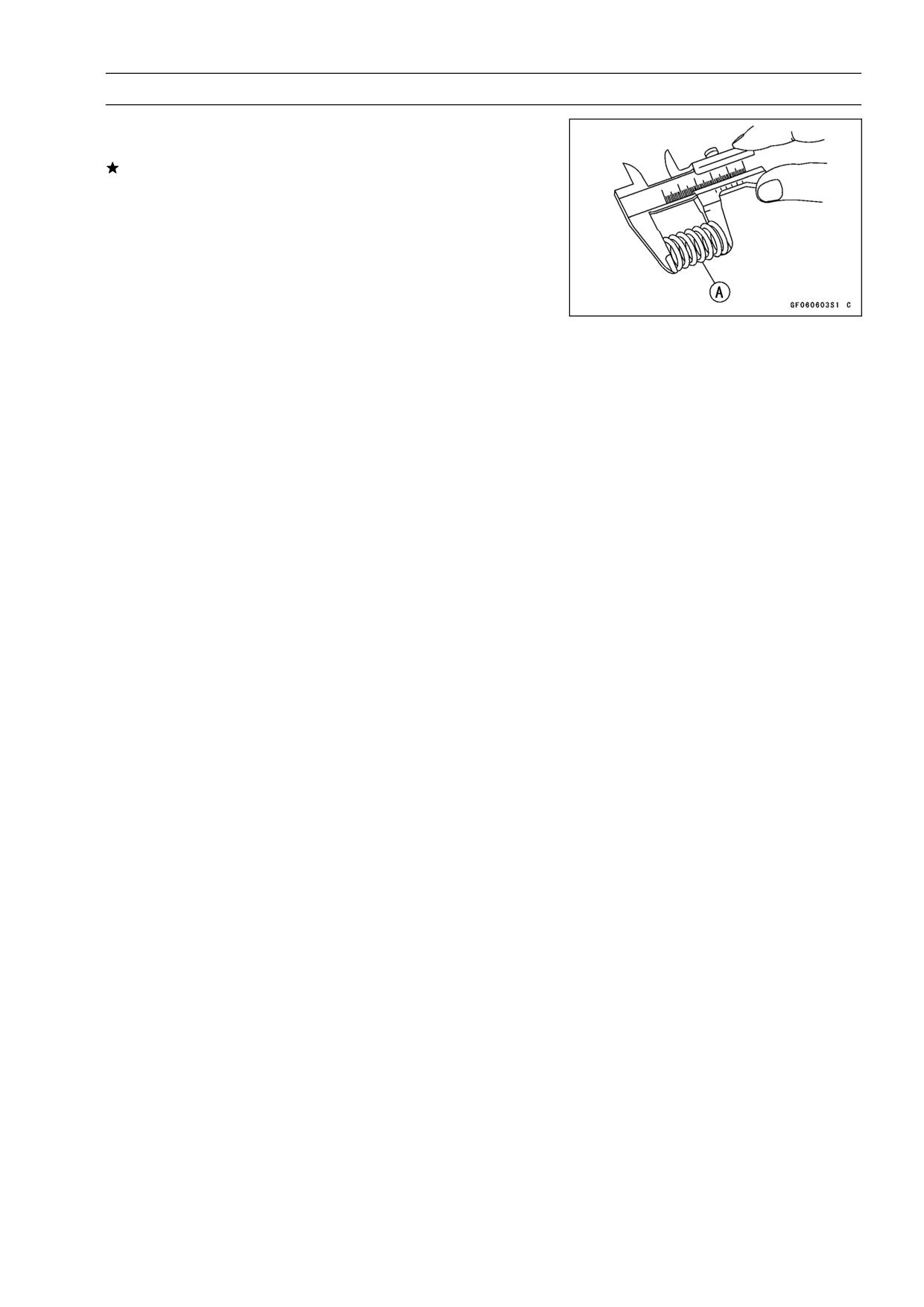
Measure the free length of the clutch springs [A].
•
If any spring is shorter than the service limit, it must be
replaced.
Clutch Spring Free Length
Standard:
82.1 mm (3.23 in.)
Service Limit:
78.0 mm (3.07 in.)
ENGINE LUBRICATION SYSTEM 6-1
Engine Lubrication System
Table of Contents
Exploded View
6-2
Engine Oil Flow Chart
6-3
Specifications
6-4
Engine Oil and Oil Filter
6-5
Oil Level Inspection
6-5
Engine Oil Change
6-5
6
Oil Filter Change
6-6
Oil Pan
6-7
Oil Pan Removal
6-7
Oil Pan Installation
6-7
Oil Pressure Relief Valve
6-8
Oil Pressure Relief Valve Removal
6-8
Oil Pressure Relief Valve Installation
6-8
Oil Pressure Relief Valve Inspection
6-8
Oil Pump
6-9
Oil Pump Removal
6-9
Oil Pump Installation
6-9
Oil Pump Drive Gear Removal
6-10
Oil Pump Drive Gear Installation
6-10
Oil Cooler
6-11
Oil Cooler Removal
6-11
Oil Cooler Installation
6-11
Oil Pressure Measurement
6-12
Oil Pressure Measurement
6-12
Oil Pressure Switch
6-13
Oil Pressure Switch Removal
6-13
Oil Pressure Switch Installation
6-13
6-2 ENGINE LUBRICATION SYSTEM
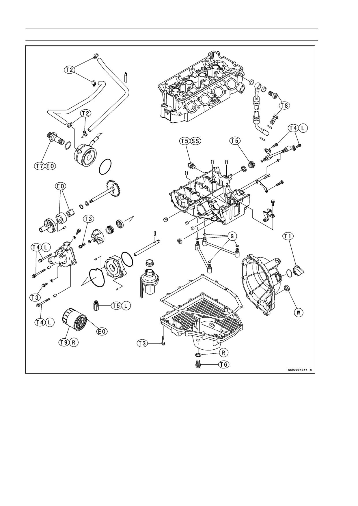
Exploded View
T1: 1.5 N·m (0.15 kgf·m, 13 in·lb) or Hand
T8: 25 N·m (2.5 kgf·m, 18 ft·lb)
-Tight
T9: 31 N·m (3.2 kgf·m, 23 ft·lb)
T2: 2.0 N·m (0.20 kgf·m, 17 in·lb)
EO: Apply engine oil.
T3: 9.8 N·m (1.0 kgf·m, 87 in·lb)
G: Apply grease.
T4: 12 N·m (1.2 kgf·m, 104 in·lb)
L: Apply a non-permanent locking agent
T5: 15 N·m (1.5 kgf·m, 11 ft·lb)
R: Replacement Parts
T6: 20 N·m (2.0 kgf·m, 14.5 ft·lb)
SS: Apply silicone sealant.
T7: 78 N·m (8.0 kgf·m, 58 ft·lb)
W: Apply water.
ENGINE LUBRICATION SYSTEM 6-3
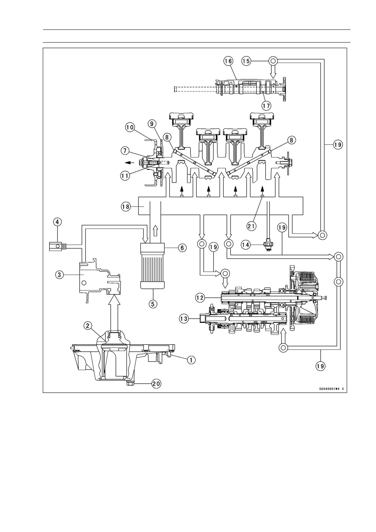
Engine Oil Flow Chart
1. Oil Pan
12. Drive Shaft
2. Oil Screen
13. Output Shaft
3. Oil Pump
14. Oil Pressure Switch
4. Oil Pressure Relief Valve
15. Cylinder Head
5. Oil Filter
16. Camshaft Cap
6. Oil Cooler
17. Camshaft
7. Crankshaft
18. Oil Passage
8. To Connecting Rod Journals
19. Oil Pipe
9. Starter Clutch Gear
20. Oil Drain Plug
10. Alternator Rotor
21. Oil Nozzles
11. Starter Clutch Oil Passage Hole
6-4 ENGINE LUBRICATION SYSTEM
Specifications
Item
Standard
Engine Oil
ZX600-J1 ∼ J2
ZX600-J3 ∼
Grade
API SE, SF or SG
←
API SH, SJ or SL with JASO MA
←
Viscosity
SAE 10W-40, 10W-50, 20W-40, or 20W-50
SAE10W-40
Capacity
3.4 L (3.6 US qt) (when filter is not removed)
←
3.6 L (3.8 US qt) (when filter is removed)
←
4.0 L (4.2 US qt) (when engine is completely dry)
←
Level
Between upper and lower level lines
←
Oil Pressure Measurement
Oil pressure @4 000 r/min
120 ∼ 180 kPa (1.2 ∼ 1.8 kgf/cm², 17 ∼ 26 psi)
(rpm), oil temperature 90°C
(194°F)
Special Tools - Outside Circlip Pliers: 57001-144
Oil Pressure Gauge, 10 kgf/cm²: 57001-164
Oil Filter Wrench: 57001-1249
Oil Pressure Gauge Adapter, M18 × 1.5: 57001-1278
Sealant - Kawasaki Bond (Silicone Sealant): 56019-120
ENGINE LUBRICATION SYSTEM 6-5
Engine Oil and Oil Filter
WARNING
Motorcycle operation with insufficient, deteri-
orated, or contaminated engine oil will cause
accelerated wear and may result in engine or trans-
mission seizure, accident, and injury.
Oil Level Inspection
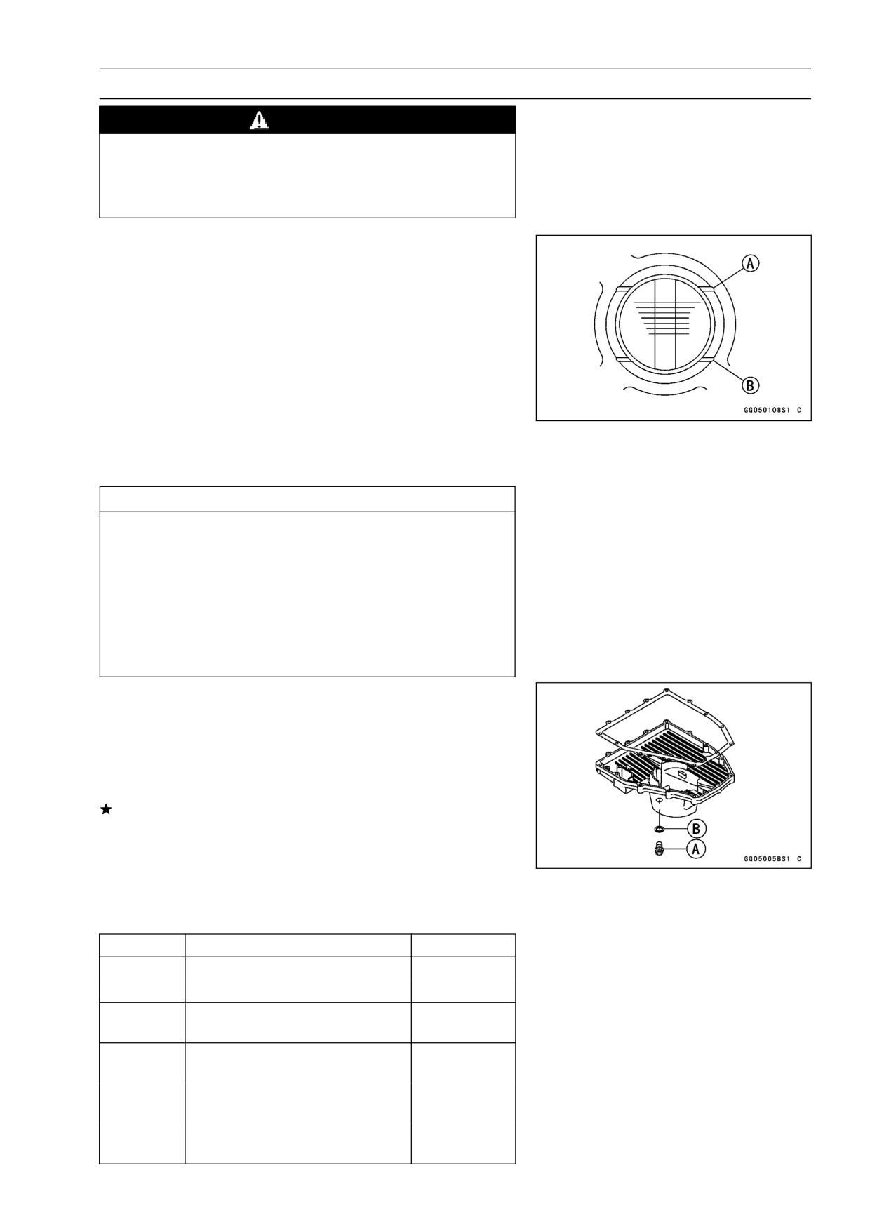
Check that the engine oil level is between the upper [A]
•
and lower [B] levels in the gauge.
NOTE
○Situate the motorcycle so that it is perpendicular to the
ground.
○If the motorcycle has just been used, wait several min-
utes for all the oil to drain down.
○If the oil has just been changed, start the engine and
run it for several minutes at idle speed. This fills the oil
filter with oil. Stop the engine, then wait several minutes
until the oil settles.
CAUTION
Racing the engine before the oil reaches every part
can cause engine seizure.
If the engine oil gets extremely low or if the oil pump
or oil passages clog up or otherwise do not function
properly, the oil pressure warning light will light. If
this light stays on when the engine is running above
idle speed, stop the engine immediately and find the
cause.
Engine Oil Change
Situate the motorcycle so that it is vertical after warming
•
up the engine.
Remove the engine drain plug [A] to drain the oil.
•
○The oil in the oil filter can be drained by removing the filter
(see Oil Filter Change).
Replace the drain plug gasket [B] with a new one if it is
damaged.
Tighten the drain plug.
•
Torque - Engine Drain Plug: 20 N·m (2.0 kgf·m, 14.5 ft·lb)
Pour in the specified type and amount of oil.
•
Engine Oil
ZX600-J1 ∼ J2
ZX600-J3 ∼
Grade:
API SE, SF or SG
←
API SH, SJ or SL with JASO MA
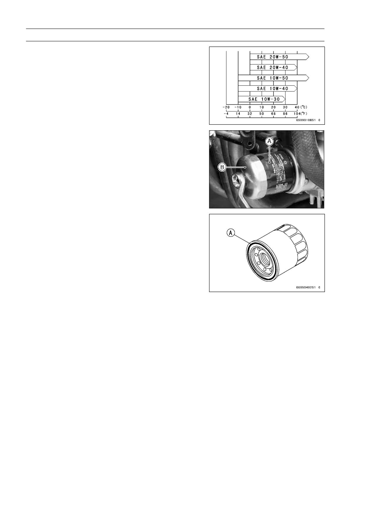
SAE 10W40, 10W50, 20W40, or
Viscosity:
SAE 10W40
20W50
3.4 L (3.6 US qt) (when filter is
Amount:
←
not removed)
3.6 L (3.8 US qt) (when filter is
←
removed)
4.0 L (4.2 US qt) (when engine
←
is completely dry)
6-6 ENGINE LUBRICATION SYSTEM
Engine Oil and Oil Filter
NOTE
○Although 10W-40 engine oil is the recommended oil
for most conditions, the oil viscosity may need to be
changed to accommodate atmospheric conditions in
your riding area.
Oil Filter Change
Drain the engine oil (see Engine Oil Change).
•
Remove:
•
Left Lower Fairing (see Frame chapter)
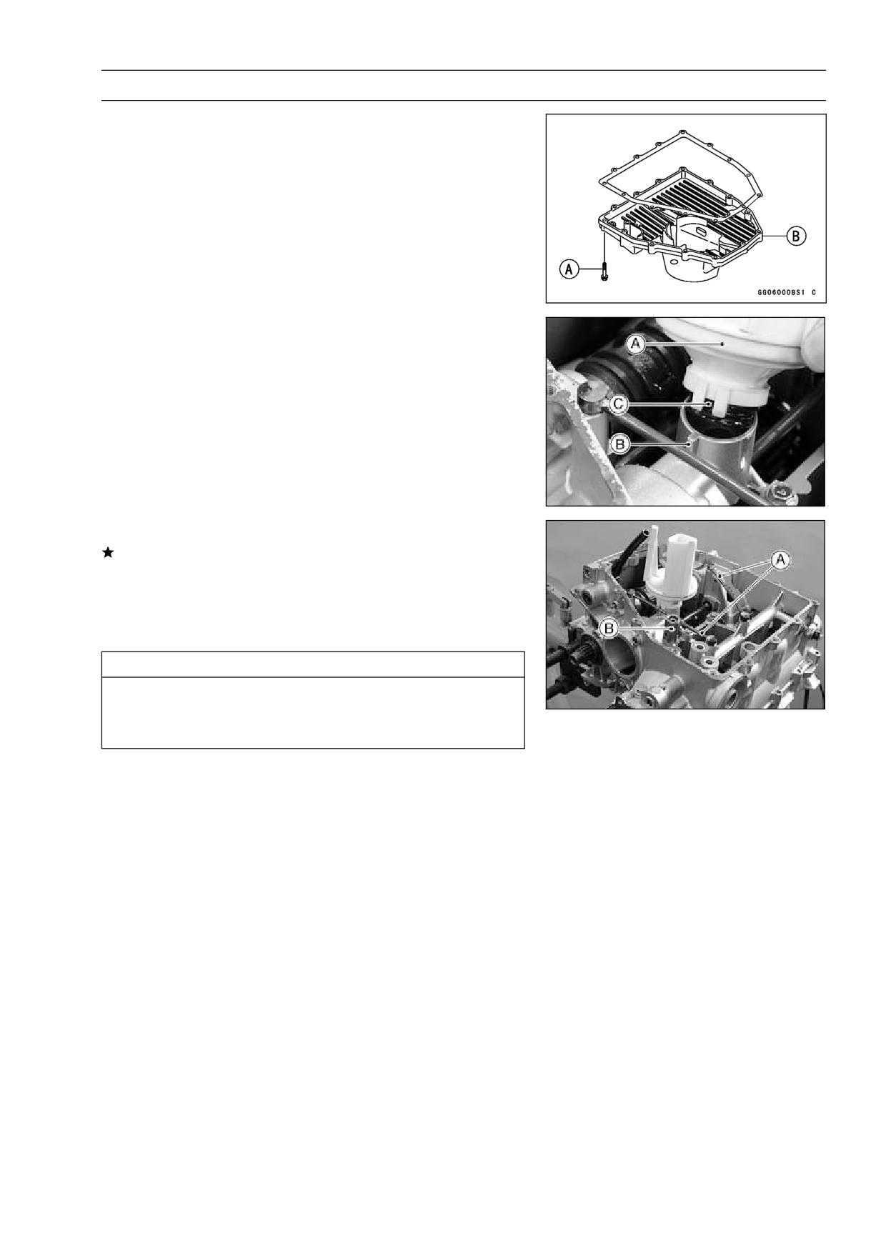
Remove the oil filter [A] with the oil filter wrench [B].
•
Special Tool - Oil Filter Wrench: 57001-1249
Replace the filter with a new one.
•
Apply engine oil to the gasket [A] before installation.
•
Tighten the filter with the oil filter wrench.
•
Torque - Oil Filter: 31 N·m (3.2 kgf·m, 23 ft·lb)
NOTE
○Hand tightening of the oil filter can not be allowed since
it does not reach to this tightening torque.
Pour in the specified type and amount of oil (see Engine
•
Oil Change).
ENGINE LUBRICATION SYSTEM 6-7
Oil Pan
Oil Pan Removal
Remove:
•
Engine Oil (drain, see Engine Oil Change)
Muffler (see Engine Top End chapter)
Oil Pan Bolts [A]
Oil Pan [B]
Oil Pan Installation
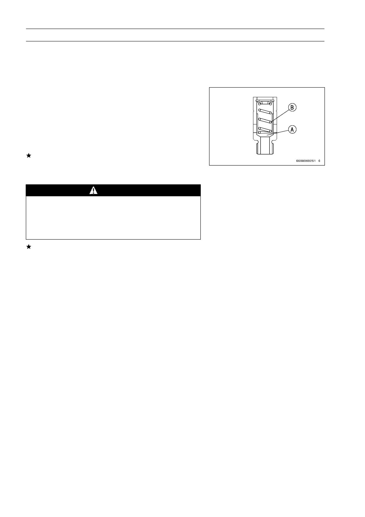
Clean the oil screen [A].
•
Install the oil screen so that the crankcase rib [B] fits the
•
slot [C] of the oil screen.
Apply grease to the O-rings on the oil pipes [A].
•
If the relief valve was removed, install it.
○Apply a non-permanent locking agent to the threads of
the relief valve [B], and tighten it.
Torque - Oil Pressure Relief Valve: 15 N·m (1.5 kgf·m, 11
ft·lb)
CAUTION
Do not apply too much non-permanent locking
agent to the threads. This may block the oil pas-
sage.
Replace the oil pan gasket with a new one.
•
Tighten:
•
Torque - Oil Pan Bolts: 9.8 N·m (1.0 kgf·m, 87 in·lb)
6-8 ENGINE LUBRICATION SYSTEM
Oil Pressure Relief Valve
Oil Pressure Relief Valve Removal
See the Oil Pan Removal.
•
Oil Pressure Relief Valve Installation
See the Oil Pan Installation.
•
Oil Pressure Relief Valve Inspection
Check to see if the valve [A] slides smoothly when push-
•
ing it in with a wooden or other soft rod, and see if it comes
back to its seat by spring [B] pressure.
NOTE
○Inspect the valve in its assembled state. Disassembly
and assembly may change the valve performance.
If any rough spots are found during above inspection,
wash the valve clean with a high-flash point solvent and
blow out any foreign particles that may be in the valve with
compressed air.
WARNING
Clean the relief valve in a well-ventilated area, and
take care that there is no spark or flame anywhere
near the working area. Because of the danger of
highly flammable liquids, do not use gasoline or low
-flash point solvent.
If cleaning does not solve the problem, replace the relief
valve as an assembly. The relief valve is precision made
with no allowance for replacement of individual parts.
ENGINE LUBRICATION SYSTEM 6-9
Oil Pump
Oil Pump Removal
Drain:
•
Coolant (see Cooling System chapter)
Engine Oil (see Engine Oil Change)
Remove:
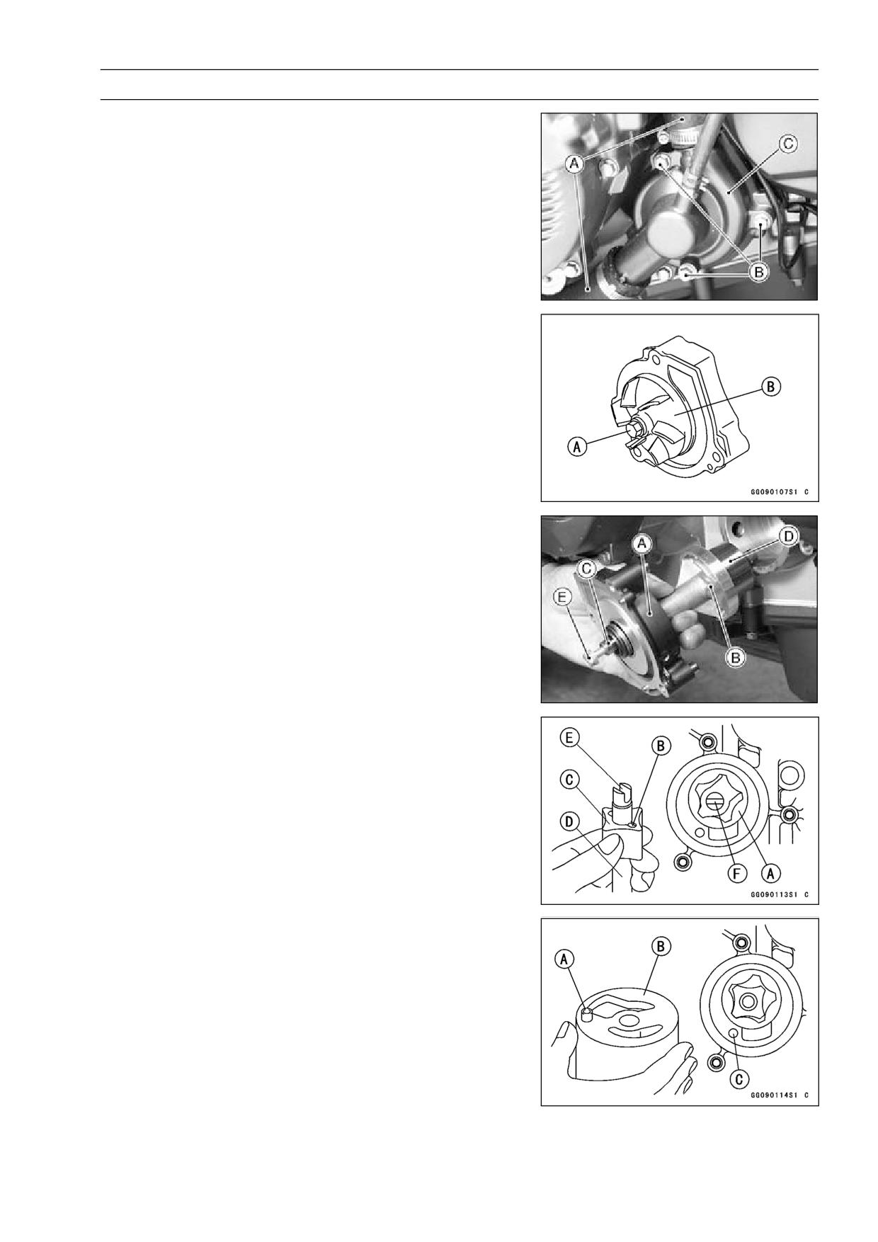
•
Water Hoses [A]
Bolts [B] and Water Pump Cover [C]
Impeller Bolt [A]
Impeller [B]
Water Pump Body [A]
Oil Pump Cover [B]
Oil (Water) Pump Shaft [C]
Outer Rotor [D] and Inner Rotor
NOTE
○The oil (water) pump assembly can easily be removed
by installing water pump cover bolt [E] into the oil (water)
pump shaft and pulling them.
Oil Pump Installation
Install the outer rotor [A] in to the crankcase.
•
Install the pin [B], inner rotor [C] and oil (water) pump shaft
•
[D].
○Turn the pump shaft so that the slot [E] in its shaft fits onto
the projection [F] of the pump drive gear shaft.
Fit the pin [A] of the oil pump cover [B] into the hole [C] in
•
the crankcase.
6-10 ENGINE LUBRICATION SYSTEM
Oil Pump
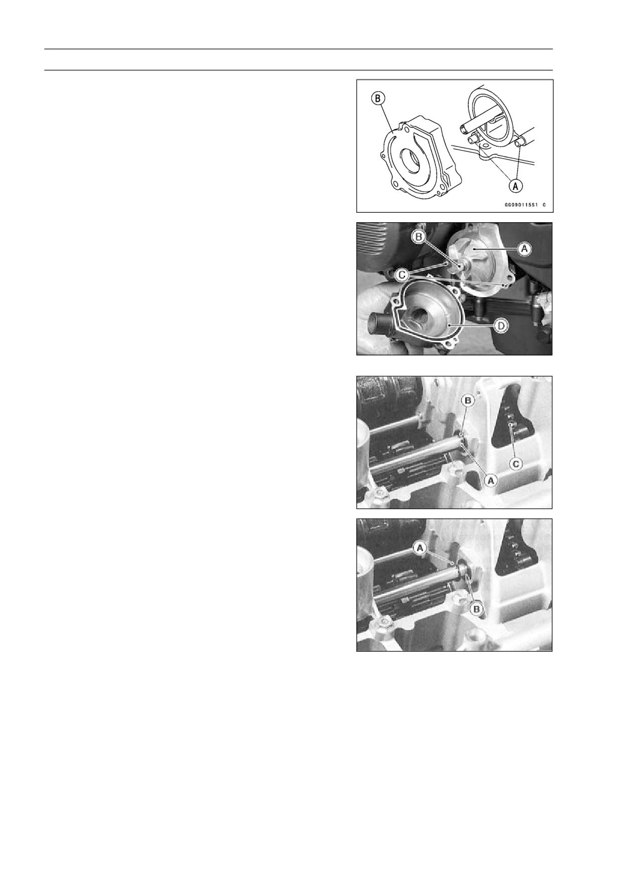
Install:
•
Pins [A]
Water Pump Body [B]
Impeller [A] and Bolt [B]
Tighten:
•
Torque - Impeller Bolt: 9.8 N·m (1.0 kgf·m, 87 in·lb)
Install:
•
Pins [C]
Water Pump Cover [D]
Apply a non-permanent locking agent to the threads of
•
the water pump cover bolts, and tighten them.
Torque - Water Pump Cover Bolts: 12 N·m (1.2 kgf·m, 104
in·lb)
Oil Pump Drive Gear Removal
Remove:
•
Clutch (see Clutch chapter)
Oil Pan (see Oil Pan Removal)
Circlip [A] and Washer [B]
Special Tool - Outside Circlip Pliers: 57001-144
Oil Pump Drive Gear [C]
Oil Pump Drive Gear Installation
Install the circlip [A] into the groove [B] of the oil pump
•
drive gear shaft.
Special Tool - Outside Circlip Pliers: 57001-144
ENGINE LUBRICATION SYSTEM 6-11
Oil Cooler
Oil Cooler Removal
Remove:
•
Lower Fairing (see Frame chapter)
Drain:
•
Engine Oil (see Engine Oil Change)
Coolant (see Cooling System chapter)
Remove the oil filter.
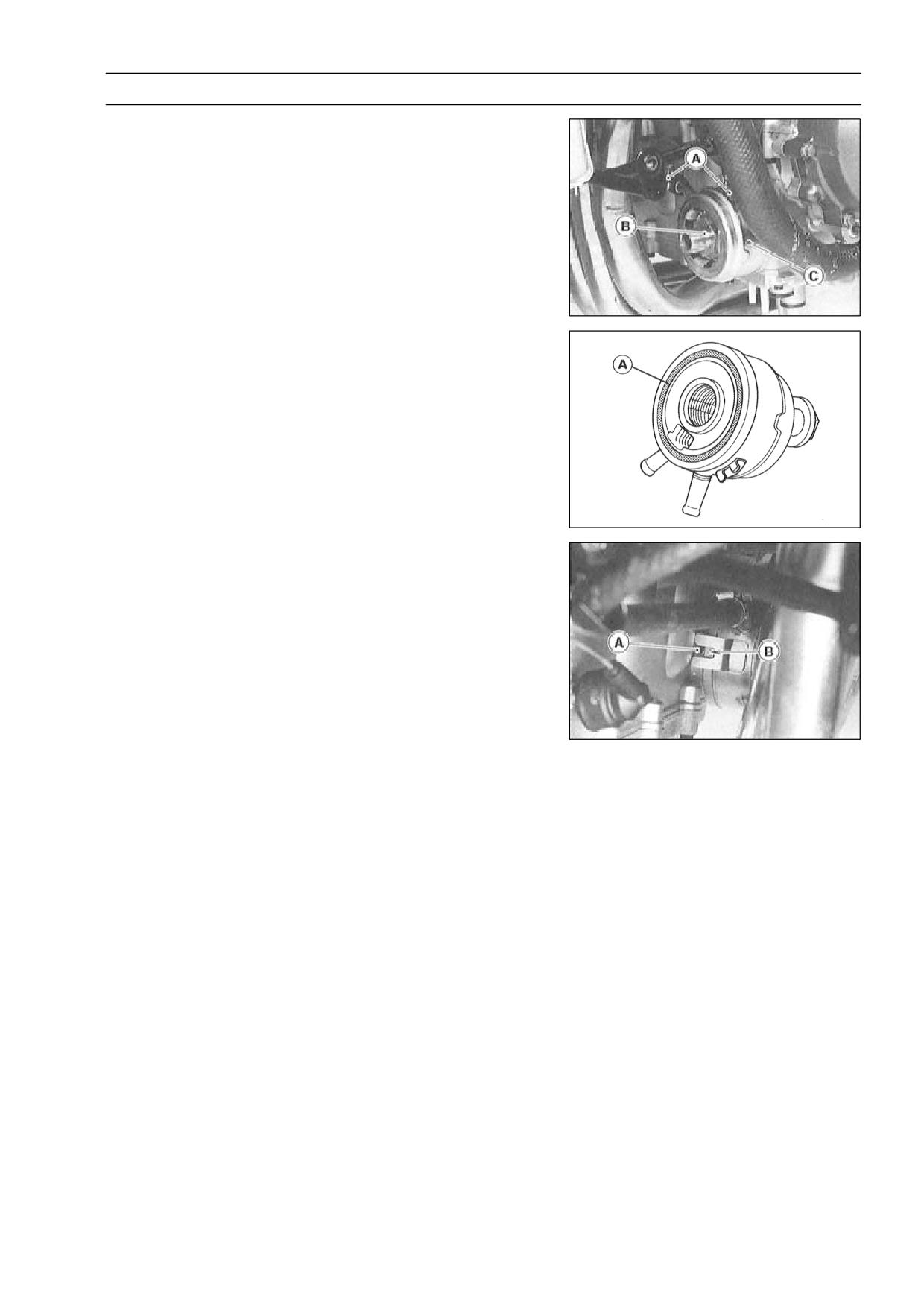
•
Remove the oil cooler hoses [A] from the oil cooler.
•
Unscrew the oil cooler bolt [B] from the crankcase, and
•
remove the oil cooler [C].
Oil Cooler Installation
Apply grease to the O-ring [A] before installation.
•
Apply engine oil to the oil cooler bolt, and install the oil
•
cooler with the bolt.
Install the oil cooler so that the crankcase rib [A] fits the
•
slot [B] of the oil cooler.
Tighten:
•
Torque - Oil Cooler Mounting Bolt: 78 N·m (8.0 kgf·m, 58
ft·lb)
Pour:
•
Engine Oil (see Engine Oil Change)
Coolant (see Cooling System chapter)
6-12 ENGINE LUBRICATION SYSTEM
Oil Pressure Measurement
Oil Pressure Measurement
Remove the lower fairing (see Frame chapter).
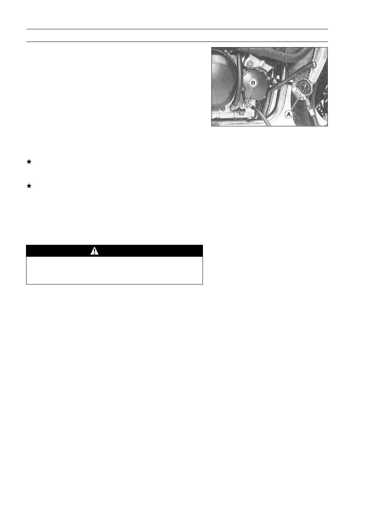
•
Remove the oil passage plug, and attach the gauge [A]
•
and adapter [B] to the plug hole.
Special Tools - Oil Pressure Gauge, 10 kgf/cm²: 57001-164
Oil Pressure Gauge Adapter, M18 × 1.5:
57001-1278
Start the engine and warm up the engine.
•
Run the engine at the specified speed, and read the oil
•
pressure gauge.
If the oil pressure is much lower than the standard, check
the oil pump, oil pump relief valve, and/or crankshaft bear-
ing insert wear immediately.
If the reading is much higher than the standard, check the
oil passaged for clogging.
Oil Pressure
Standard:
120 ∼ 180 kPa (1.2 ∼ 1.8 kgf/cm², 17 ∼ 26 psi)
@4 000 r/min (rpm), oil temp. 90°C (194 °F)
Stop the engine.
•
Remove the oil pressure gauge and adapter.
•
WARNING
Take care against burns form hot engine oil that
will drain through the oil passage when the gauge
adapter is removed.
Install the oil passage plug and tighten it.
•
Torque - Oil Passage Plug (Right): 15 N·m (1.5 kgf·m, 11
ft·lb)
ENGINE LUBRICATION SYSTEM 6-13
Oil Pressure Switch
Oil Pressure Switch Removal
Remove:
•
Right Lower Fairing (see Frame chapter)
Engine Oil (drain, see Engine Oil Change)
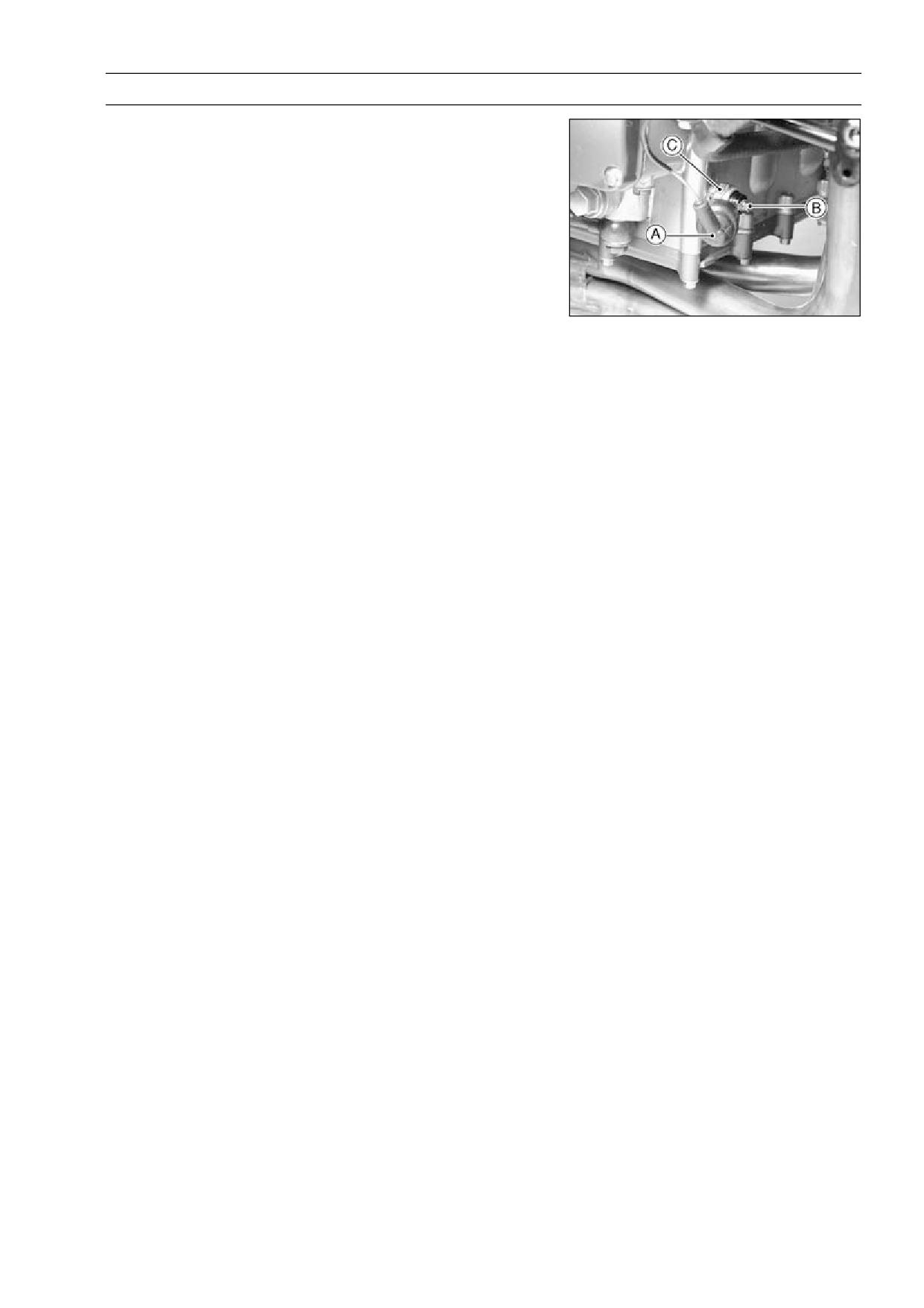
Switch Cover [A]
Switch Terminal [B]
Oil Pressure Switch [C]
Oil Pressure Switch Installation
Apply silicone sealant to the threads of the oil pressure
•
switch and tighten it.
Sealant - Kawasaki Bond (Silicone Sealant): 56019-120
Torque - Oil Pressure Switch: 15 N·m (1.5 kgf·m, 11 ft·lb)
Tighten:
•
Torque - Oil Pressure Switch Terminal Bolt: 1.5 N·m (0.15
kgf·m, 13 in·lb)
Apply grease to the terminal.
•
ENGINE REMOVAL/INSTALLATION 7-1
Engine Removal/Installation
Table of Contents
Exploded View
7-2
Specifications
7-3
Engine Removal/Installation
7-4
Engine Removal
7-4
Engine Installation
7-5
7
7-2 ENGINE REMOVAL/INSTALLATION
Exploded View
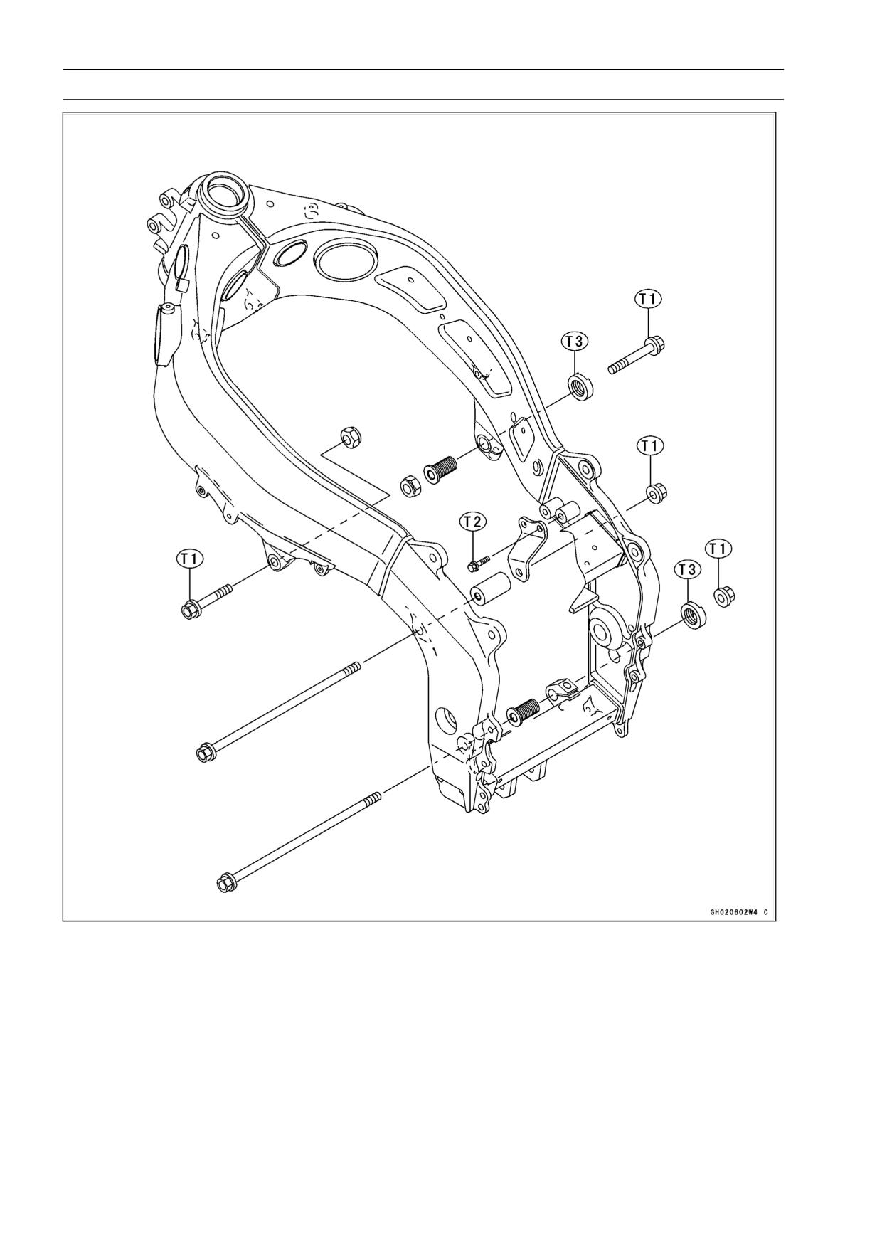
T1: 44 N·m (4.5 kgf·m, 33 ft·lb)
T2: 25 N·m (2.5 kgf·m, 18 ft·lb)
T3: 49 N·m (5.0 kgf·m, 36 ft·lb)
ENGINE REMOVAL/INSTALLATION 7-3
Specifications
Special Tool - Jack: 57001-1238
Engine Mount Nut Wrench: 57001-1450
7-4 ENGINE REMOVAL/INSTALLATION
Engine Removal/Installation
Engine Removal
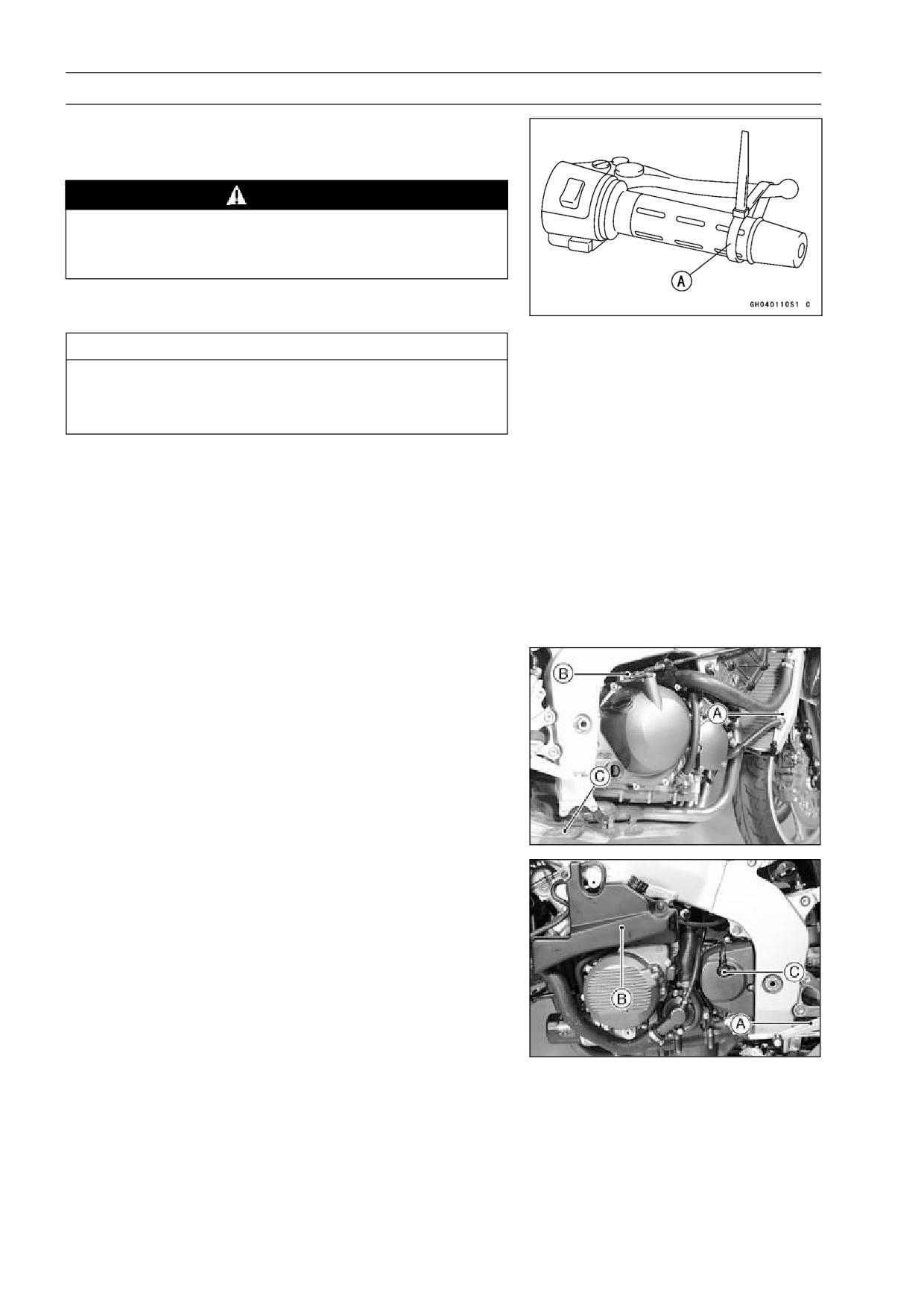
Squeeze the brake lever slowly and hold it with a band
•
[A].
WARNING
Be sure to hold the front brake when removing the
engine, or the motorcycle may fall over. It could
cause an accident and injury.
CAUTION
Be sure to hold the front brake when removing the
engine, or the motorcycle may fall over. The engine
or the motorcycle could be damaged.
Drain:
•
Engine Oil (see Engine Lubrication System chapter)
Coolant (see Cooling System chapter)
Remove:
•
Lower Fairings (see Frame chapter)
Fuel Tank (see Fuel System chapter)
Air Cleaner Housing (see Fuel System chapter)
Carburetors (see Fuel System chapter)
Baffle Plate on the Cylinder Head Cover
Radiator [A]
Clutch Cable Lower End [B]
Muffler [C]
Shift Lever [A]
Reserve Tank [B]
Speed Sensor [C]
Engine Sprocket (see Final Drive chapter)
ENGINE REMOVAL/INSTALLATION 7-5
Engine Removal/Installation
Pull off the connectors from the engine and free the wiring
•
from the clamps.
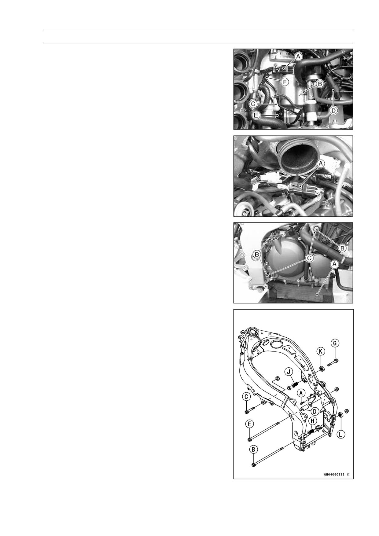
Crankshaft Sensor Lead Connector [A]
Battery Ground Cable [B]
Starter Motor Cable [C]
Alternator Lead Connector [D]
Side Stand Switch Lead Connector [E]
Speed Sensor Connector [F]
Stick Coil Harness Connector [A]
Support the rear part of the frame on the jack.
•
Special Tool - Jack: 57001-1238
Support the engine with a suitable stand [A].
•
Remove the engine mounting bolts and nuts [B].
•
Loosen the locknuts and adjusting bolts [C].
•
Special Tool - Engine Mount Nut Wrench: 57001-1450
Remove the drive chain from the output shaft.
•
Using the stand, take out the engine.
•
Engine Installation
Before engine installation loosen the engine bracket bolts
•
[A].
Support the engine with a suitable stand.
•
Hang the drive chain over the output shaft just before
•
moving the engine into its final position in the frame.
Screw the adjusting bolts [H], [J] into the frame.
•
Insert the lower mounting bolt [B].
•
Insert the upper mounting bolts [C], [G].
•
Set the collar [D] and insert the middle mounting bolts [E].
•
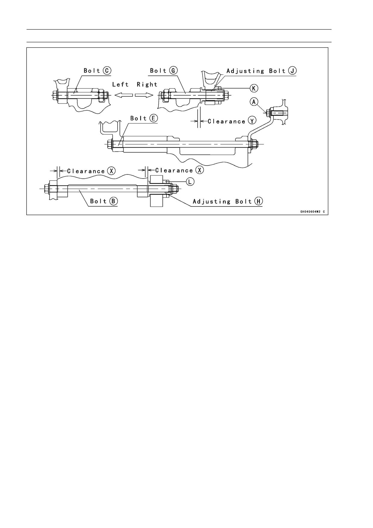
7-6 ENGINE REMOVAL/INSTALLATION
Engine Removal/Installation
Turn the adjusting bolt [H] until the clearance [X] between
•
the crankcase and frame come to zero mm.
Tighten the bracket bolts [A].
•
Torque - Engine Bracket Bolts: 25 N·m (2.5 kgf·m, 18 ft·lb)
Tighten the engine mounting bolts [C], [B], [E] and locknut
•
[L] with specified torque.
Torque - Engine Mounting Bolts: 44 N·m (4.5 kgf·m, 33 ft·lb)
Engine Mounting Locknuts: 49 N·m (5.0 kgf·m, 36
ft·lb)
Special Tool - Engine Mount Nut Wrench: 57001-1450
Pull out the engine mounting bolt [G] temporarily, and turn
•
the adjusting bolt [J] until the clearance [Y] between the
adjusting bolt and cylinder come to zero mm.
Insert the bolt [G] into engine mounting hole, and tighten
•
the bolt and locknut [K] with specified torque
Torque - Engine Mounting Bolts: 44 N·m (4.5 kgf·m, 33 ft·lb)
Engine Mounting Locknuts: 49 N·m (5.0 kgf·m, 36
ft·lb)
Special Tool - Engine Mount Nut Wrench: 57001-1450
Run the leads, cables and hoses correctly (see Cable,
•
Wire and Hose Routing section in the General Information
chapter).
Install the removed parts (see appropriate chapters).
•
Adjust:
•
Throttle Cables (see Fuel System chapter)
Choke Cable (see Fuel System chapter)
Clutch Cable (see Clutch chapter)
Drive Chain (see Final drive chapter)
Fill the engine with engine oil (see Engine Lubrication
•
System chapter).
Fill the engine with coolant and bleed the air from the
•
cooling system (see Cooling System chapter).
CRANKSHAFT/TRANSMISSION 8-1
Crankshaft/Transmission
Table of Contents
Exploded View
8-2
Starter Motor Clutch Inspection ...
8-17
Specifications
8-4
Starter Motor Clutch Disassembly
8-17
Crankcase Splitting
8-6
Starter Motor Clutch Assembly
8-17
Crankcase Splitting
8-6
Transmission
8-18
Crankcase Assembly
8-7
Shift Pedal Removal
8-18
Crankshaft and Connecting Rods
8-9
Shift Pedal Installation
8-18
Crankshaft Removal
8-9
External Shift Mechanism
Crankshaft Installation
8-9
Removal
8-18
Connecting Rod Removal
8-9
External Shift Mechanism
Connecting Rod Installation
8-9
Installation
8-18
Crankshaft/Connecting Rod
External Shift Mechanism
8
Cleaning
8-12
Inspection
8-19
Connecting Rod Bend Inspection
8-12
Transmission Shaft Removal
8-19
Connecting Rod Twist Inspection.
8-13
Transmission Shaft Installation
8-19
Connecting Rod Big End Side
Transmission Shaft Disassembly.
8-20
Clearance Inspeciton
8-13
Transmission Shaft Assembly
8-20
Connecting Rod Big End
Shift Drum and Fork Removal
8-21
Bearing Insert/Crankpin Wear
Shift Drum and Fork Installation...
8-22
Inspection
8-13
Shift Drum Disassembly
8-22
Crankshaft Side Clearance
Shift Drum Assembly
8-22
Inspection
8-15
Shift Fork Bending Inspection
8-22
Crankshaft Runout Inspection
8-15
Shift Fork/Gear Groove Wear
Crankshaft Main Bearing
Inspection
8-23
Insert/Journal Wear Inspection .
8-15
Shift Fork Guide Pin/Drum
Starter Motor Clutch
8-17
Groove Wear Inspection
8-23
Starter Motor Clutch
Gear Dog and Gear Dog Hole
Removal/Installation
8-17
Damage Inspection
8-23
8-2 CRANKSHAFT/TRANSMISSION
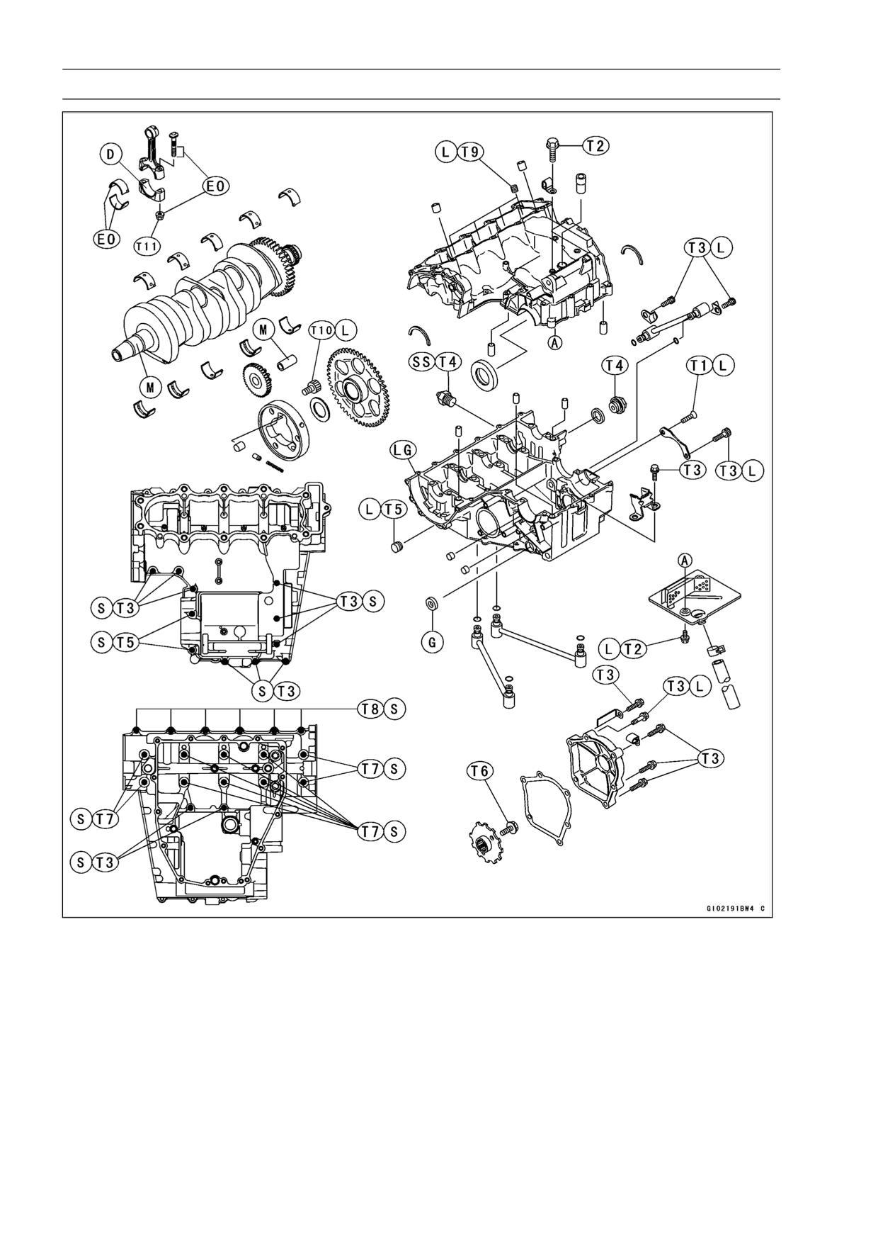
Exploded View
T1: 4.9 N·m (0.5 kgf·m, 43 in·lb)
T11: See the text.
T2: 9.8 N·m (1.0 kgf·m, 87 in·lb)
D: Do not apply any grease or oil.
T3: 12 N·m (1.2 kgf·m, 104 in·lb)
EO: Apply engine oil.
T4: 15 N·m (1.5 kgf·m, 11 ft·lb)
G: Apply grease.
T5: 20 N·m (2.0 kgf·m, 14.5 ft·lb)
L: Apply a non-permanent locking agent.
T6: 44 N·m (4.5 kgf·m, 33 ft·lb)
LG: Apply silicone sealant (92104-1063).
T7: 30 N·m (3.0 kgf·m, 22 ft·lb)
M: Apply molybdenum disulfide grease.
T8: 18 N·m (1.8 kgf·m, 13 ft·lb)
S: Tighten the fasteners following the speci-
T9: 6.9 N·m (0.70 kgf·m, 61 in·lb)
fied sequence.
T10: 34 N·m (3.5 kgf·m, 25 ft·lb)
SS: Apply silicone sealant (56019-120).
CRANKSHAFT/TRANSMISSION 8-3
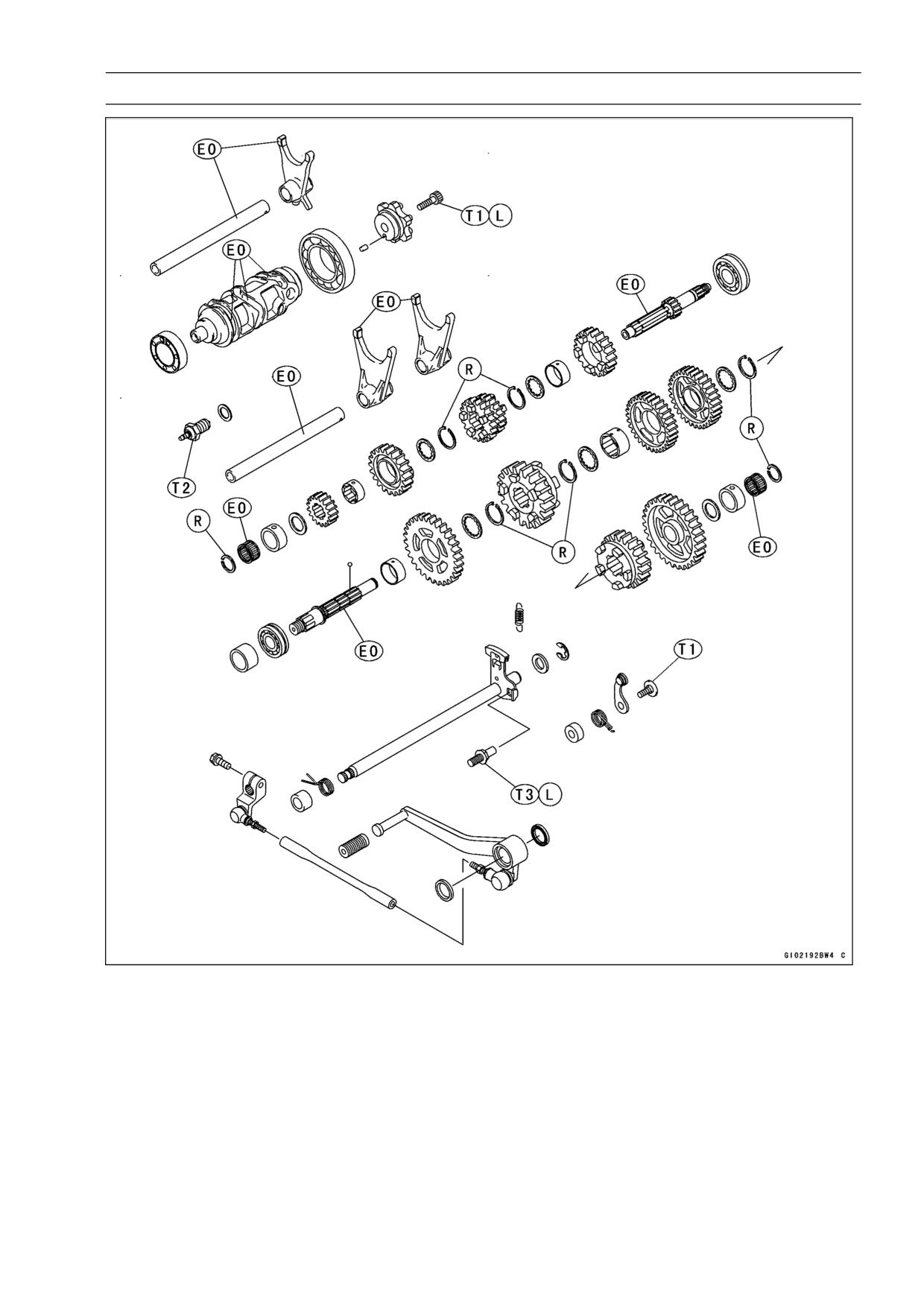
Exploded View
T1: 12 N·m (1.2 kgf·m, 104 in·lb)
T2: 15 N·m (1.5 kgf·m, 11 ft·lb)
T3: 28 N·m (2.9 kgf·m, 21 ft·lb)
EO: Apply engine oil.
L: Apply a non-permanent locking agent.
R: Replacement Parts
8-4 CRANKSHAFT/TRANSMISSION
Specifications
Item
Standard
Service Limit
Crankshaft, Connecting Rods
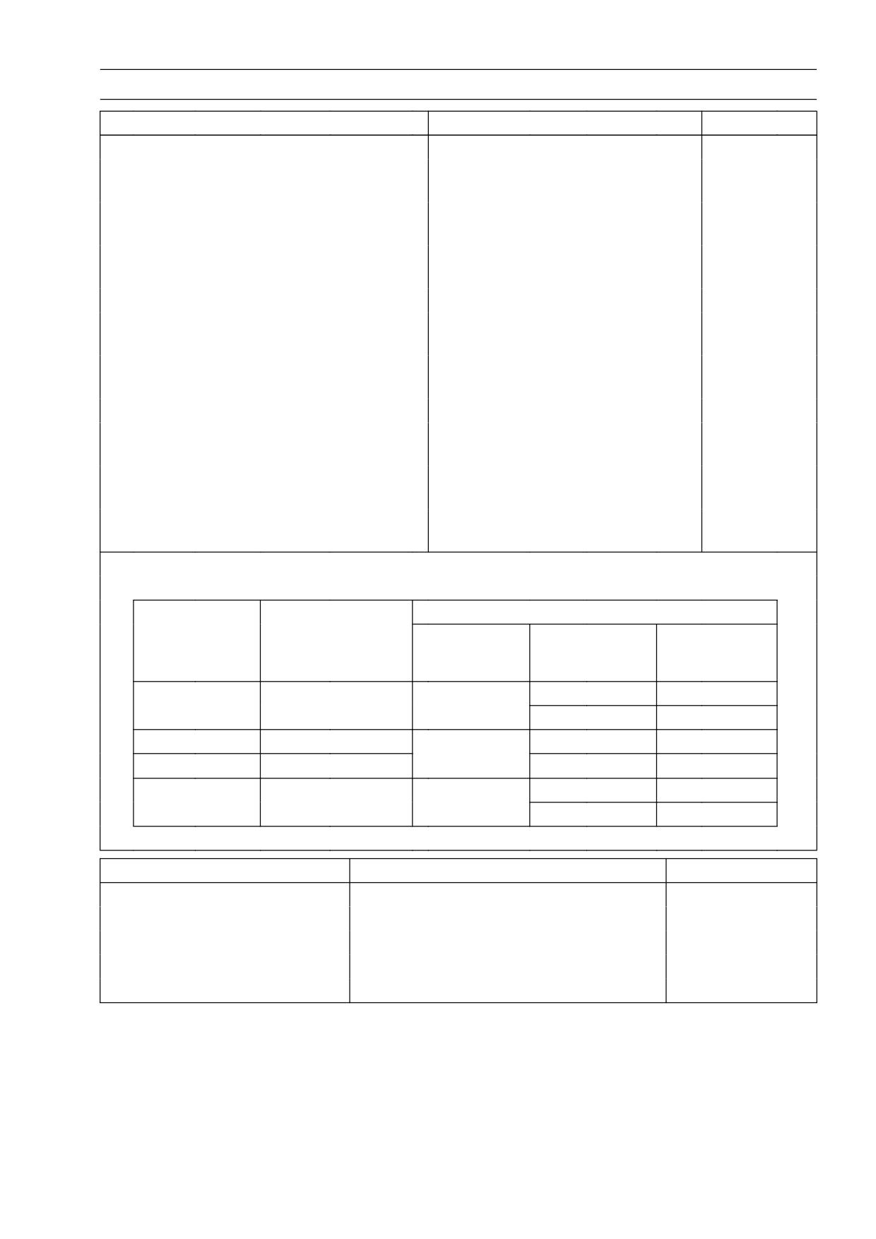
Connecting Rod Big End Side Clearance
0.13 ∼ 0.33 mm (0.0051 ∼ 0.0130 in.)
0.5 mm
(0.020 in.)
Connecting Rod Big End Bearing
0.031 ∼ 0.059 mm
0.10 mm
Insert/Crankpin Clearance
(0.0012 ∼ 0.0023 in.)
(0.004 in.)
Crankpin Diameter:
29.984 ∼ 30.000 mm
29.97 mm
(1.1805 ∼ 1.1811 in.)
(1.180 in.)
Marking:
None
29.984 ∼ 29.994 mm
- - -
(1.1805 ∼ 1.1809 in.)
○
29.995 ∼ 30.000 mm
- - -
(1.1809 ∼ 1.1811 in.)
Connecting Rod Big End Bore Diameter:
33.000 ∼ 33.016 mm
- - -
(1.2992 ∼ 1.2998 in.)
Marking:
None
33.000 ∼ 33.008 mm
- - -
(1.2992 ∼ 1.2995 in.)
○
33.009 ∼ 33.016 mm
- - -
(1.2996 ∼ 1.2998 in.)
Connecting Rod Big End Bearing Insert
Thickness:
Pink
1.475 ∼ 1.480 mm
- - -
(0.0581 ∼ 0.0583 in.)
Brown
1.480 ∼ 1.485 mm
- - -
(0.0583 ∼ 0.0585 in.)
Black
1.485 ∼ 1.490 mm
- - -
(0.0585 ∼ 0.0587 in.)
Connecting rod big end bearing insert selection:
Con-rod Big End
Bearing Insert
Crankpin Diameter
Bore Diameter
Marking
Size Color
Part Number
Marking
None
○
Pink
92028-1880
None
None
Brown
92028-1879
○
○
○
None
Black
92028-1878
Crankshaft Side Clearance
0.05 ∼ 0.20 mm (0.002 ∼ 0.008 in.)
0.40 mm
(0.016 in.)
Crankshaft Runout
TIR 0.02 (0.0008 in.) mm or less
TIR 0.05 mm
(0.002 in.)
Crankshaft Main Bearing Insert/journal
0.014 ∼ 0.038 mm
0.07 mm
Clearance
(0.0006 ∼ 0.0015 in.)
(0.0028 in.)
Crankshaft Main Journal Diameter:
29.984 ∼ 30.000 mm
29.96 mm
(1.1805 ∼ 1.1811 in.)
(1.1795 in.)
CRANKSHAFT/TRANSMISSION 8-5
Specifications
Item
Standard
Service Limit
Marking:
None
29.984 ∼ 29.994 mm
- - -
(1.1805 ∼ 1.1809 in.)
1
29.995 ∼ 30.000 mm
- - -
(1.1809 ∼ 1.1811 in.)
Crankcase Main Bearing Bore Diameter:
33.000 ∼ 33.016 mm
- - -
(1.2992 ∼ 1.2998 in.)
Marking:
○
33.000 ∼ 33.008 mm
- - -
(1.2992 ∼ 1.2995 in.)
None
33.009 ∼ 33.016 mm
- - -
(1.2996 ∼ 1.2998 in.)
Crankshaft Main Bearing Insert Thickness:
Brown
1.491 ∼ 1.495 mm
- - -
(0.0587 ∼ 0.0589 in.)
Black
1.495 ∼ 1.499 mm
- - -
(0.0589 ∼ 0.0590 in.)
Blue
1.499 ∼ 1.503 mm
- - -
(0.0590 ∼ 0.0592 in.)
Crankshaft main bearing insert selection:
Crankcase
Bearing Insert*
Crankshaft Main
Main Bearing
Journal Diameter
Bore Diameter
Size Color
Part Number
Journal Nos.
Marking
Marking
92028-1883
3, 5
○
1
Brown
92028-1886
1, 2, 4
None
1
92028-1882
3, 5
Black
○
None
92028-1885
1, 2, 4
92028-1881
3, 5
None
None
Blue
92028-1884
1, 2, 4
*The bearing inserts for Nos. 1, 2 and 4 journals have an oil groove, respectively.
Item
Standard
Service Limit
Transmission
Shift Fork Ear Thickness
5.9 ∼ 6.0 mm (0.2323 ∼ 0.2362 in.)
5.8 mm (0.228 in.)
Gear Groove Width
6.05 ∼ 6.15 mm (0.2382 ∼ 0.2421 in.)
6.25 mm (0.246 in.)
Shift Fork Guide Pin Diameter
5.9 ∼ 6.0 mm (0.2323 ∼ 0.2362 in.)
5.8 mm (0.228 in.)
Shift Drum Groove Width
6.05 ∼ 6.20 mm (0.2382 ∼ 0.2441 in.)
6.3 mm (0.248 in.)
Special Tool - Bearing Puller: 57001-135
Outside Circlip Pliers: 57001-144
Bearing Puller Adapter: 57001-317
Flywheel & Pulley Holder: 57001-1605
Sealant - Kawasaki Bond (Silicone Sealant): 56019-120
Kawasaki Bond (Silicone Sealant): 92104-1063
8-6 CRANKSHAFT/TRANSMISSION
Crankcase Splitting
Crankcase Splitting
Remove the engine (see Engine Removal/Installation
•
chapter).
Set the engine on a clean surface and hold the engine
•
steady while parts are being removed.
Remove:
•
Crankshaft Sensor (see Electrical System chapter)
Oil Hose (Cylinder Head ∼ Lower Crankcase)
Clutch (see Clutch chapter)
External Shift Mechanism (see External Shift Mecha-
nism Removal)
Starter Motor (see Electrical System chapter)
Oil Pump (see Engine Lubrication System chapter)
Alternator Rotor (see Electrical System chapter)
Oil Filter (see Engine Lubrication System chapter)
Oil Cooler (see Engine Lubrication System chapter)
If the crankshaft is to be removed, remove the pistons
(see Engine Top End chapter).
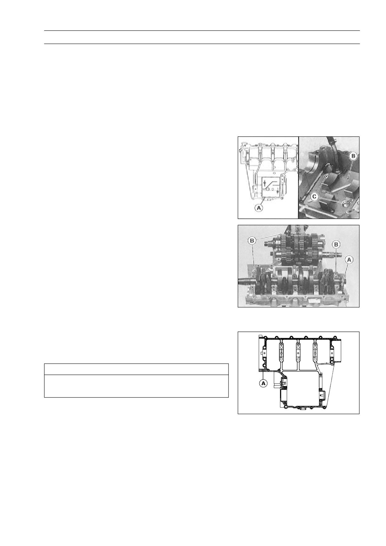
Hold the timing rotor [A] steady with the holder [B], and
•
remove the timing rotor bolt [C] and the rotor.
Special Tool - Flywheel & Pulley Holder: 57001-1605
Remove the upper crankcase bolts.
•
○First loosen the 6 mm bolts.
7 mm Bolts [A]
6 mm Bolts [B]
Remove the oil pan, oil screen and oil pipes (see Engine
•
Lubrication System chapter).
Remove the lower crankcase bolts and brackets.
•
○First loosen the 6 mm bolts.
6 mm Bolts [A]
8 mm Bolts [B]
Tap lightly around the crankcase mating surface with a
•
plastic mallet, and split the crankcase. Take care not to
damage the crankcase.
CRANKSHAFT/TRANSMISSION 8-7
Crankcase Splitting
Crankcase Assembly
NOTE
○The upper and lower crankcase halves are machined
at the factory in the assembled state, so the crankcase
halves must be replaced as a set.
With a high-flash point solvent, clean off the mating sur-
•
faces of the crankcases halves and wipe dry.
Using compressed air, blow out the oil passages in the
•
crankcase halves.
Apply silicone sealant to the breather plate mating surface
•
[A] 1 to 1.5 mm (0.04 ∼ 0.06 in.) thick, wait until sealant
dries, and then install the breather plate [B].
Sealant - Kawasaki Bond (Silicone Sealant): 92104-1063
Apply a non-permanent locking agent to the threads and
•
tighten the bolts [C].
Torque - Breather Plate Bolts: 9.8 N·m (1.0 kgf·m, 87 in·lb)
Install:
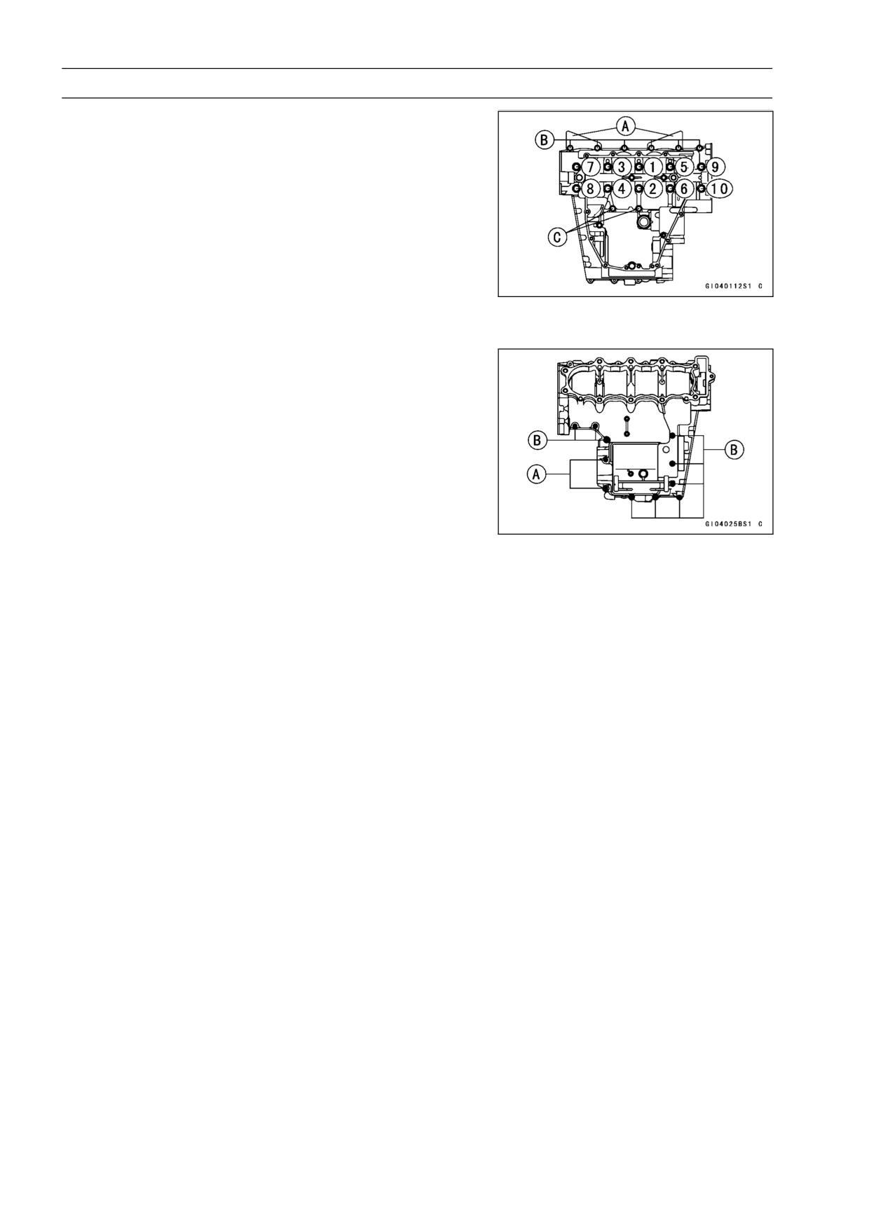
•
Crankshaft and Connecting Rods
Camshaft Chain [A]
Transmission Shaft and Gears
Dowel Pins [B]
Shift Drum
Shift Forks and Shift Rods
Before fitting the lower case on the upper case, check the
•
following.
○Be sure to hang the camshaft chain on the crankshaft.
○Check to see that the shift drum and transmission gears
are in the neutral position.
Apply silicon sealant [A] to the mating surface of the lower
•
crankcase half.
Sealant - Kawasaki Bond (Silicone Sealant): 92104-1063
CAUTION
Do not apply silicone sealant around the crankshaft
main bearing inserts, and oil passage holes.
8-8 CRANKSHAFT/TRANSMISSION
Crankcase Splitting
Tighten the lower crankcase bolts, using the following
•
steps.
○Following the sequence numbers on the lower crankcase
half, tighten the 8 mm bolts [1 ∼ 10].
Torque - Crankcase 8 mm Bolts: 30 N·m (3.0 kgf·m, 22 ft·lb)
○Install the brackets [A] and tighten the 6 mm bolts [B].
Torque - Crankcase (L38 mm) 6 mm Bolts:
18 N·m (1.8
kgf·m, 13 ft·lb)
○Tighten the 6 mm bolts [C].
Torque - Crankcase 6 mm Bolts: 12 N·m (1.2 kgf·m, 104
in·lb)
Tighten the upper crankcase bolts, in the order listed.
•
Torque - Crankcase 7 mm Bolts [A]: 20 N·m (2.0 kgf·m, 14.5
ft·lb)
Crankcase 6 mm Bolts [B]: 12 N·m (1.2 kgf·m, 104
in·lb)
After tightening all crankcase bolts, check the following
•
items.
○Crankshaft and transmission shafts turn freely.
○While spinning the output shaft, gears shift smoothly from
the 1st to 6th gear, and 6th to 1st.
○When the output shaft stays still, the gear can not be
shifted to 2nd gear or other higher gear positions.
CRANKSHAFT/TRANSMISSION 8-9
Crankshaft and Connecting Rods
Crankshaft Removal
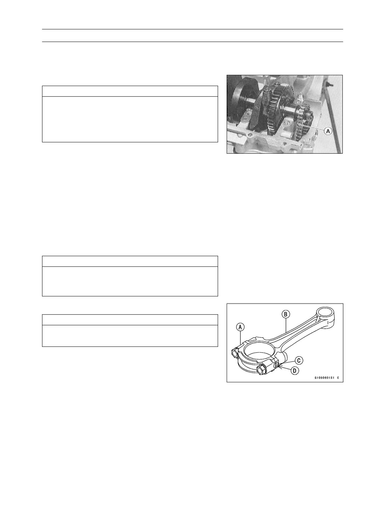
Split the crankcase (see Crankcase Splitting).
•
Remove the crankshaft.
•
Crankshaft Installation
CAUTION
If the crankshaft, bearing inserts, or crankcase
halves are replaced with new ones, select the bear-
ing inserts and check clearance with a plastigage
(press gauge) before assembling engine to be sure
the correct bearing inserts are installed.
Apply engine oil to the crankshaft main bearing inserts.
•
Install the crankshaft with the camshaft chain [A] hanging
•
on it.
Connecting Rod Removal
Split the crankcase (see Crankcase Splitting).
•
Remove the connecting rod nuts.
•
Remove the crankshaft.
•
NOTE
○Mark and record the locations of the connecting rods
and their big end caps so that they can be reassembled
in their original positions.
Remove the connecting rods from the crankshaft.
•
CAUTION
Discard the connecting rod bolts. To prevent dam-
age to the crankpin surfaces, do not allow the con-
necting rod bolts to bump against the crankpins.
Connecting Rod Installation
CAUTION
To minimize vibration, the connecting rods should
have the same weight mark.
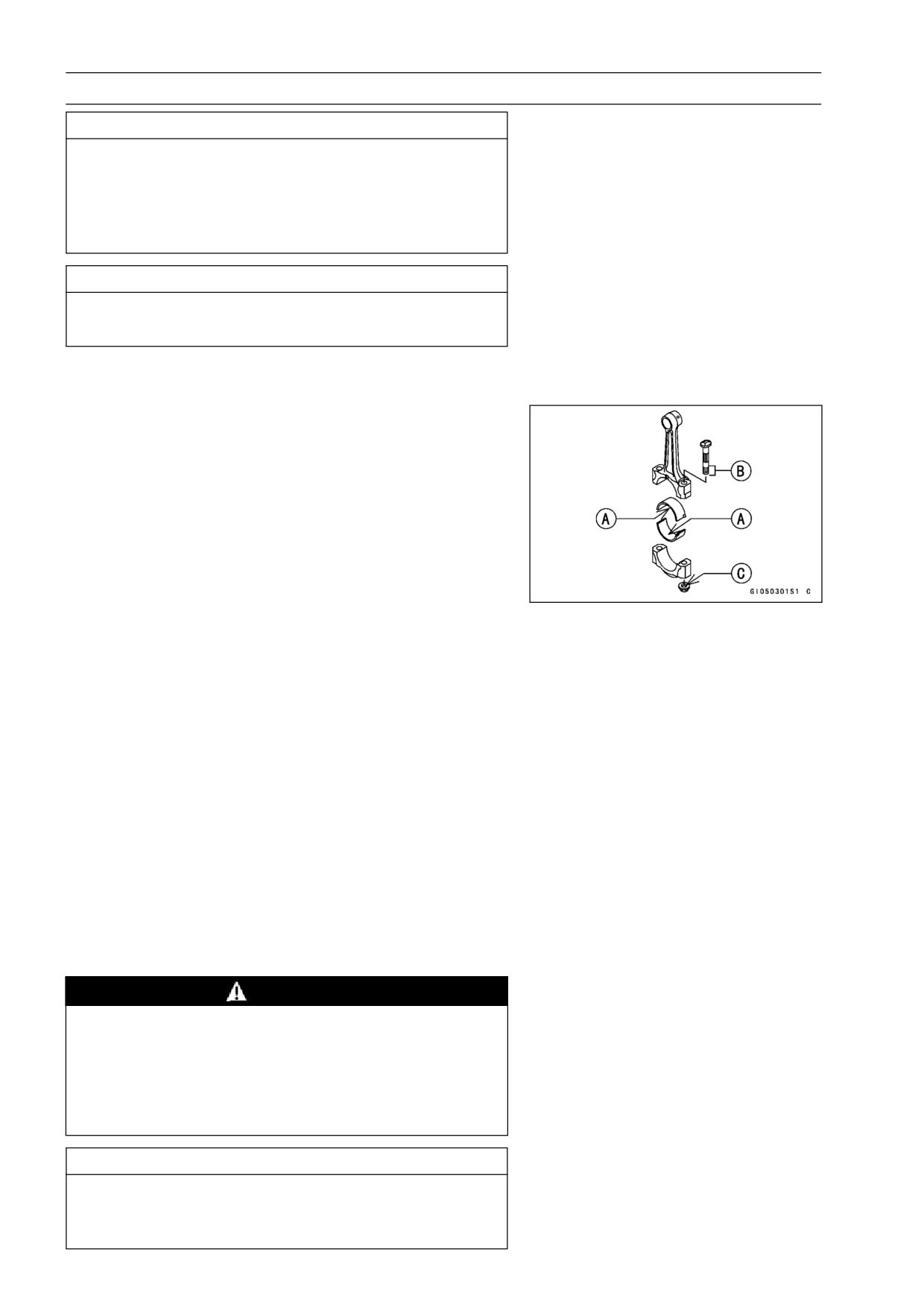
Big End Cap [A]
Connecting Rod [B]
Weight Mark, Alphabet [C]
Diameter Mark (Around Weight Mark) [D]: “○” or no
mark
8-10 CRANKSHAFT/TRANSMISSION
Crankshaft and Connecting Rods
CAUTION
If the connecting rods, big end bearing inserts, or
crankshaft are replaced with new ones, select the
bearing insert and check clearance with a plasti-
gage (press gauge) before assembling engine to be
sure the correct bearing inserts are installed.
CAUTION
The connecting rod bolts are designed to stretch
when tightened. Never reuse them.
Replace the connecting rod big end bolts and nuts with
•
new ones.
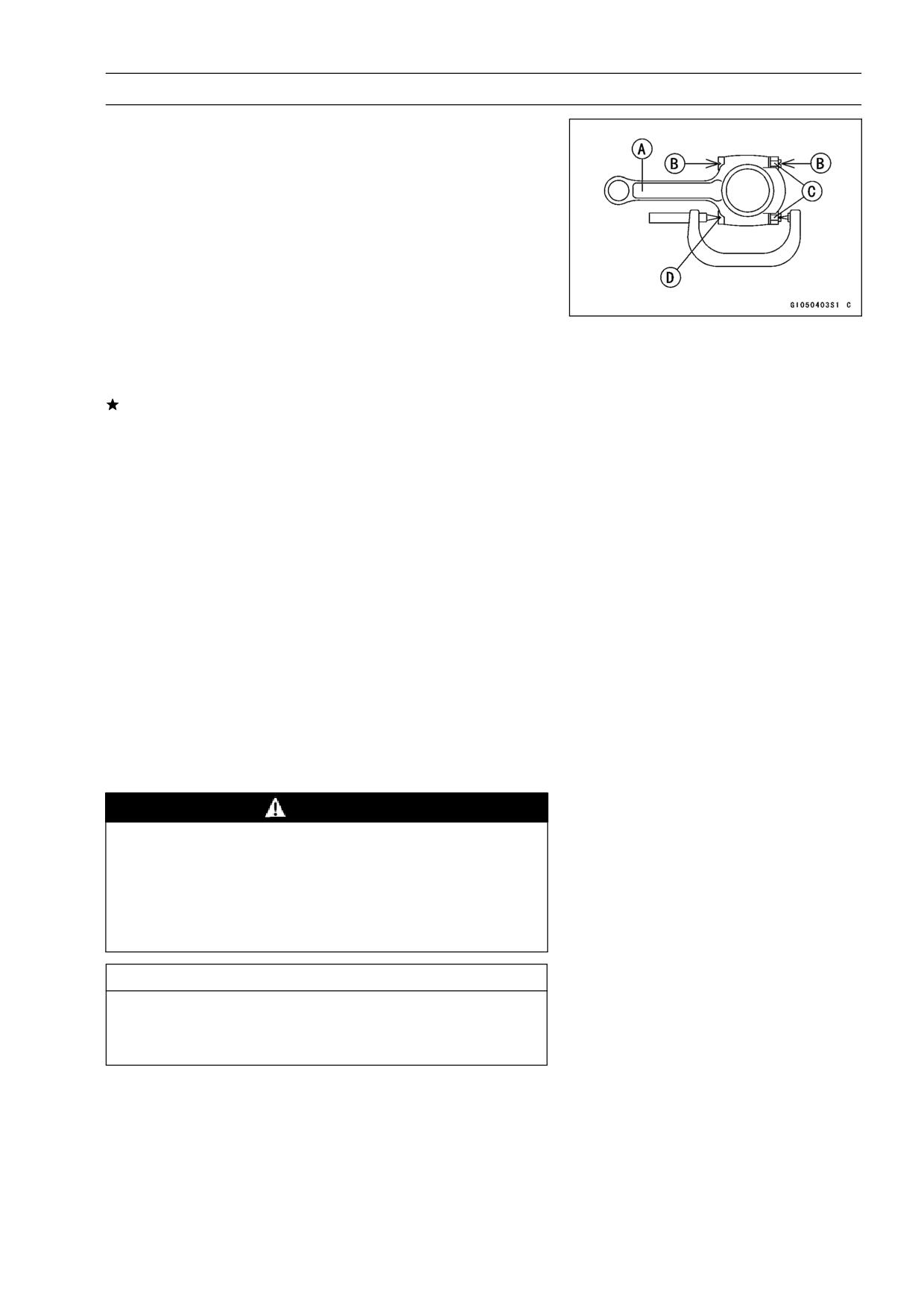
Apply engine oil to the inner surface of upper and lower
•
bearing inserts [A].
Apply a small amount of the engine oil to the threads [B]
•
and seating surface [C] of the connecting rod nuts.
○The connecting rod big end is bolted using the “plastic
region fastening method”.
○This method precisely achieves the needed clamping
force without exceeding it unnecessarily, allowing the
use of thinner, lighter bolts further decreasing connecting
rod weight.
○There are two types of the plastic region fastening. One
is a bolt length measurement method and other is a tight-
ening torque method. Observe one of the following two,
but the bolt length measurement method is preferable be-
cause this is a more reliable way to tighten the big end
nuts.
(1) Bolt Length Measurement Method
Be sure to clean the bolts, nuts, and connecting rods
•
thoroughly with high-flash point solvent, because the new
connecting rods, bolts, and nuts are treated with an anti
-rust solution.
WARNING
Clean the bolts, nuts, and connecting rods in a well
-ventilated area, and take care that there is no spark
or flame anywhere near the working area. This in-
cludes any appliance with a pilot light. Because of
the danger of highly flammable liquids, do not use
gasoline or low-flash point solvents to clean them.
CAUTION
Immediately dry the bolts and nuts with com-
pressed air after cleaning.
Clean and dry the bolts and nuts completely.
CRANKSHAFT/TRANSMISSION 8-11
Crankshaft and Connecting Rods
Install new bolts in reused connecting rods.
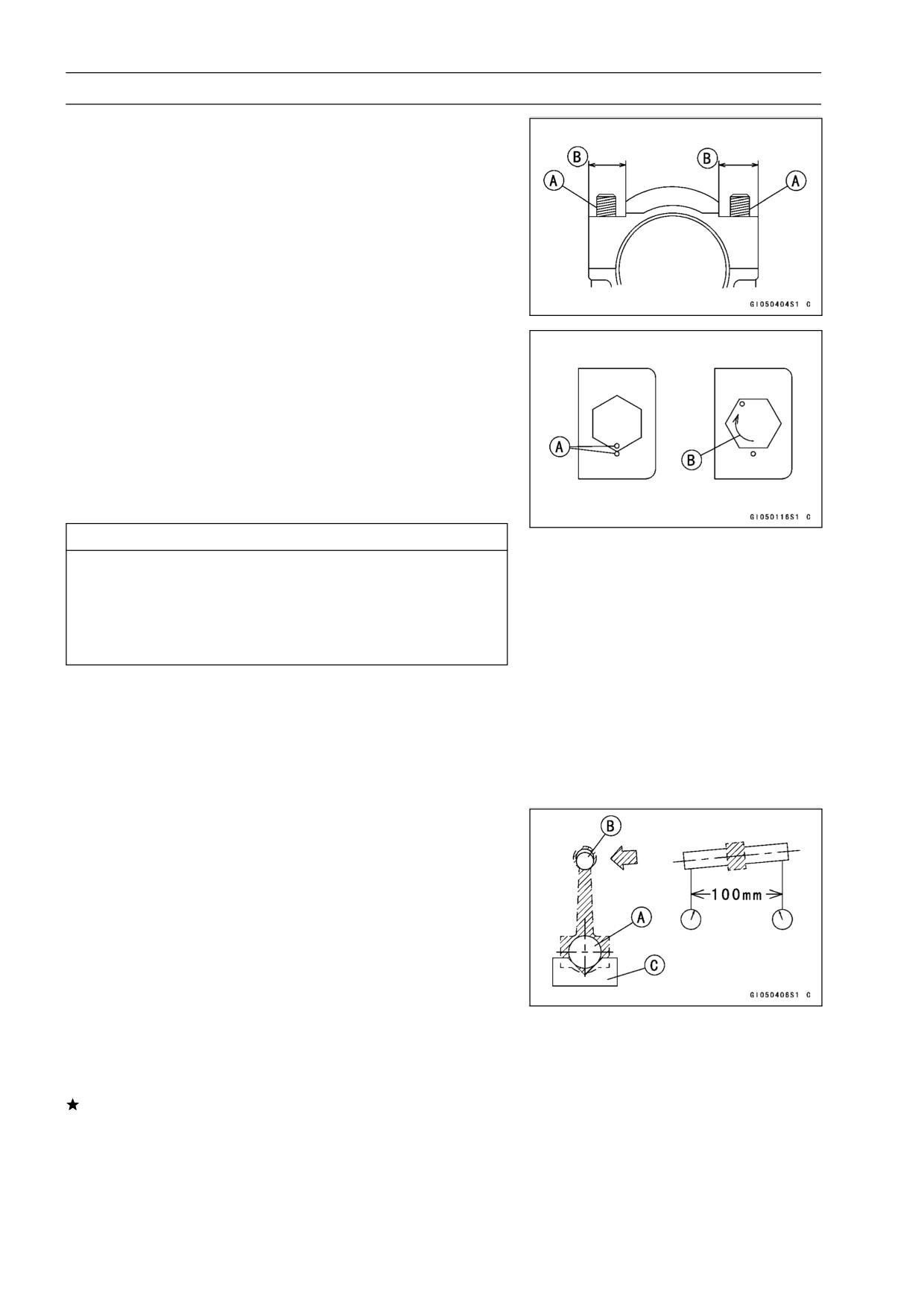
•
Dent both bolt head and bolt tip with a punch as shown.
•
Before tightening, use a point micrometer to measure the
•
length of new connecting rod bolts and record the values
to find the bolt stretch.
Connecting Rod [A]
Dent here with a punch [B]
Nuts [C]
Fit micrometer pins into dents [D]
Tighten the big end nuts until the bolt elongation reaches
•
the length specified in the table.
Check the length of the connecting rod bolts.
•
If the stretch is more than the usable range, the bolt has
stretched too much. An overlongated bolt may break in
use.
Bolt Length after
Bolt Length
-
=
Stretch
tightening
before tightening
Usable Range of
0.30 ∼ 0.40 mm (0.012 ∼
Connecting Rod Bolt
0.016 in.) (ZX600-J1 ∼ J3)
Stretch
Usable Range of
0.18 ∼ 0.28 mm (0.007 ∼
Connecting Rod Bolt
0.011 in.) (ZX600-J4 ∼)
Stretch
(2) Tightening Torque Method
If you don’t have a point micrometer, you may tighten the
•
nuts using the “Tightening Torque Method”.
Be sure to clean the bolts, nuts, and connecting rods
•
thoroughly with high-flash point solvent, because the new
connecting rods, bolts, and nuts are treated with an anti
-rust solution.
WARNING
Clean the bolts, nuts, and connecting rods in a well
-ventilated area, and take care that there is no spark
or flame anywhere near the working area. This in-
cludes any appliance with a pilot light. Because of
the danger of highly flammable liquids, do not use
gasoline or low-flash point solvents to clean them.
CAUTION
Immediately dry the bolts and nuts with com-
pressed air after cleaning.
Clean and dry the bolts and nuts completely.
8-12 CRANKSHAFT/TRANSMISSION
Crankshaft and Connecting Rods
Apply a small amount of engine oil to the threads [A] and
•
seating surface [B] of the connecting rod nuts.
First, tighten the nuts to the specified torque.
•
Next, tighten the nuts 160° more.
•
○Mark [A] the connecting rod big end caps and nuts so that
nuts can be turned 160° [B] properly.
Torque + Angle-
15 N·m (1.5 kgf·m, 11 ft·lb) + 160° (ZX600-J1 ∼ J3)
Torque + Angle-
15 N·m (1.5 kgf·m, 11 ft·lb) + 120° (ZX600-J4 ∼)
CAUTION
Since the friction force of the mating surface and
thread portion of new nuts is different from that
of used ones, the nut tightening torque should be
changed as specified in the above table.
Be careful not to overtighten the nuts.
Crankshaft/Connecting Rod Cleaning
After removing the connecting rods from the crankshaft,
•
clean them with a high-flash point solvent.
Blow the crankshaft oil passages with compressed air to
•
remove any foreign particles or residue that may have
accumulated in the passages.
Connecting Rod Bend Inspection
Remove the connecting rod big end bearing insets, and
•
reinstall the connecting rod big end cap.
Select an arbor [A] of the same diameter as the connect-
•
ing rod big end, and insert the arbor through the connect-
ing rod big end.
Select an arbor of the same diameter as the piston pin
•
and at least 100 mm (3.94 in.) long, and insert the arbor
[B] through the connecting rod small end.
On a surface plate, set the big-end arbor on V block [C].
•
With the connecting rod held vertically, use a height
•
gauge to measure the difference in the height of the
arbor above the surface plate over a 100 mm (3.94 in.)
length to determine the amount of connecting rod bend.
If connecting rod bend exceeds the service limit, the con-
necting rod must be replaced.
Connecting Rod Bend
Service Limit: TIR 0.2/100 mm (0.008/3.94 in.)
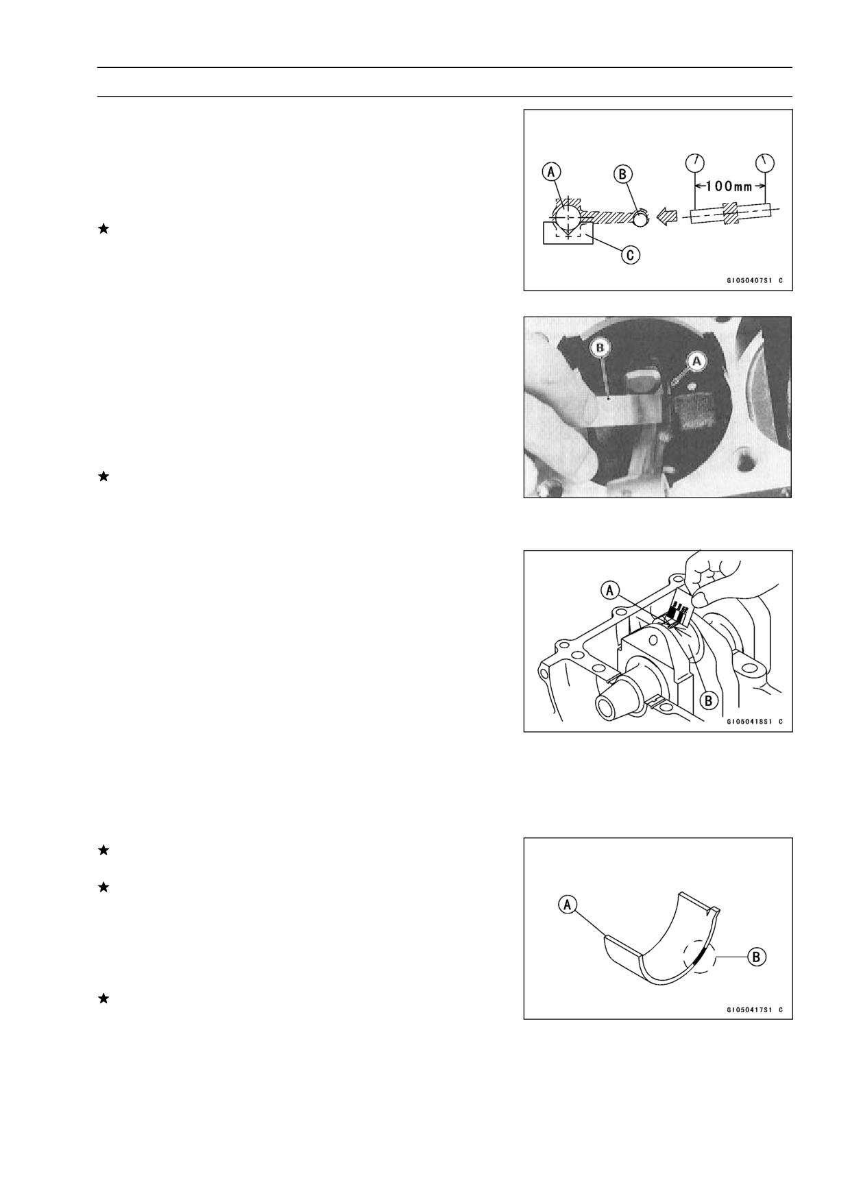
CRANKSHAFT/TRANSMISSION 8-13
Crankshaft and Connecting Rods
Connecting Rod Twist Inspection
With the big-end arbor [A] still on V block [C], hold the
•
connecting rod horizontally and measure the amount that
the arbor [B] varies from being paralleled with the surface
plate over a 100 mm (3.94 in.) length of the arbor to de-
termine the amount of connecting rod twist.
If connecting rod twist exceeds the service limit, the con-
necting rod must be replaced.
Connecting Rod Twist
Service Limit: TIR 0.2/100 mm (0.008/3.94 in.)
Connecting Rod Big End Side Clearance Inspeciton
Measure connecting rod big end side clearance [A].
•
○Insert a thickness gauge [B] between the big end and ei-
ther crank web to determine clearance.
Connecting Rod Big End Side Clearance
Standard:
0.13 ∼ 0.33 mm (0.0051 ∼ 0.0130 in.)
Service Limit:
0.5 mm (0.020 in.)
If the clearance exceeds the service limit, replace the con-
necting rod with new one and then check clearance again.
If clearance is too large after connecting rod replacement,
the crankshaft also must be replaced.
Connecting Rod Big End Bearing Insert/Crankpin
Wear Inspection
Measure the bearing insert/crankpin [B] clearance with
•
plastigage [A].
Tighten the big end nuts to the specified torque (see Con-
•
necting Rod Installation).
NOTE
○Do not move the connecting rod and crankshaft during
clearance measurement.
Connecting Rod Big End Bearing Insert/Crankpin
Clearance
Standard:
0.031 ∼ 0.059 mm (0.0012 ∼ 0.0023 in.)
Service Limit:
0.10 mm (0.004 in.)
If clearance is within the standard, no bearing replace-
ment is required.
If clearance is between 0.060 mm (0.0024 in.) and the
service limit [0.10 mm (0.004 in.)], replace the bear-
ing inserts [A] with inserts painted black [B]. Check
insert/crankpin clearance with the plastigage. The clear-
ance may exceed the standard slightly, but it must not be
less than the minimum in order to avoid bearing seizure.
If the clearance exceeds the service limit, measure the
diameter of the crankpins.
Crankpin Diameter
Standard:
29.984 ∼ 30.000 mm (1.1805 ∼ 1.1811 in.)
Service Limit:
29.97 mm (1.180 in.)
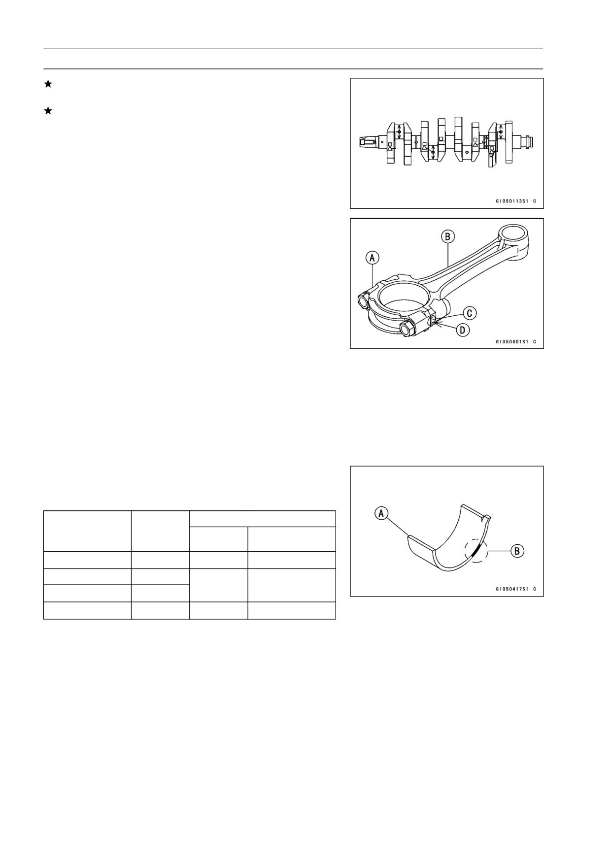
8-14 CRANKSHAFT/TRANSMISSION
Crankshaft and Connecting Rods
If any crankpin has worn past the service limit, replace the
crankshaft with a new one.
If the measured crankpin diameters are not less than the
service limit, but do not coincide with the original diameter
markings on the crankshaft, make new marks on it.
Crankpin Diameter Marks
None
29.984 ∼ 29.994 mm (1.1805 ∼ 1.1809 in.)
○
29.995 ∼ 30.000 mm (1.1809 ∼ 1.1811 in.)
Δ: Crankpin Diameter Marks, "○" mark or no mark.
Measure the connecting rod big end bore diameter, and
•
mark each connecting rod big end in accordance with the
bore diameter.
Tighten the big end nuts to the specified torque (see Con-
•
necting Rod Installation).
NOTE
○The mark already on the big end should almost coincide
with the measurement because of little wear.
Connecting Rod Big End Bore Diameter Marks
None
33.000 mm ∼ 33.008 mm (1.2992 ∼ 1.2995 in.)
○
33.009 ∼ 33.016 mm (1.2996 ∼ 1.2998 in.)
Big End Cap [A]
Connecting Rod [B]
Weight Mark, Alphabet [C]
Diameter Mark (Around Weight Mark) [D]: “○” or no
mark
Select the proper bearing insert [A] in accordance with the
•
combination of the connecting rod and crankshaft coding.
Size Color [B]
Con-rod Big End
Crankpin
Bearing Insert
Bore Diameter
Diameter
Size Color
Part Number
Marking
Marking
None
○
Pink
92028-1880
None
None
Brown
92028-1879
○
○
○
None
Black
92028-1878
Install the new inserts in the connecting rod and check
•
insert/crankpin clearance with the plastigage.
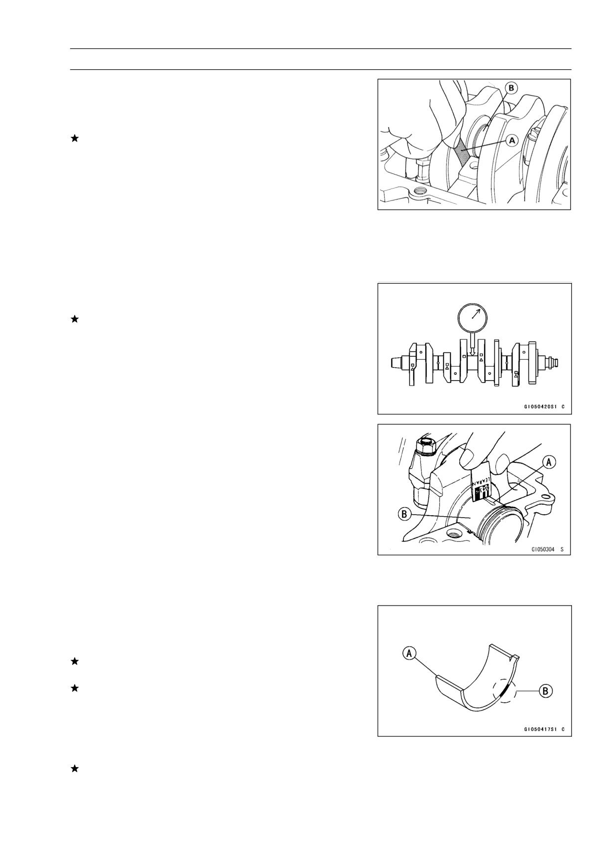
CRANKSHAFT/TRANSMISSION 8-15
Crankshaft and Connecting Rods
Crankshaft Side Clearance Inspection
Insert a thickness gauge [A] between the crankcase main
•
bearing and the crank web at the No. 2 journal [B] to
determine clearance.
If the clearance exceeds the service limit, replace the
crankcase halves as a set.
NOTE
○The upper and lower crankcase halves are machined
at the factory in the assembled state, so the crankcase
halves must be replaced as a set.
Crankshaft Side Clearance
Standard:
0.05 ∼ 0.20 mm (0.002 ∼ 0.008 in.)
Service Limit:
0.40 mm (0.016 in.)
Crankshaft Runout Inspection
Measure the crankshaft runout.
•
If the measurement exceeds the service limit, replace the
crankshaft.
Crankshaft Runout
Standard:
TIR 0.02 mm (0.0008in.) or less
Service Limit: TIR 0.05 mm (0.002 in.)
Crankshaft Main Bearing Insert/Journal Wear
Inspection
Using a plastigage (press gauge) [A], measure the bear-
•
ing insert/journal [B] clearance.
NOTE
○Tighten the crankcase bolts to the specified torque (see
Crankcase Assembly).
○Do not turn the crankshaft during clearance measure-
ment.
○Journal clearance less than 0.025 mm (0.001 in.) can
not be measured by plastigage, however, using genuine
parts maintains the minimum standard clearance.
Crankshaft Main Bearing Insert/Journal Clearance
Standard:
0.014 ∼ 0.038 mm (0.0006 ∼ 0.0015 in.)
Service Limit:
0.07 mm (0.0028 in.)
If clearance is within the standard, no bearing replace-
ment is required.
If clearance is between 0.039 mm (0.0015 in.) and the
service limit (0.07 mm (0.003 in.)), replace the bearing in-
serts with inserts [A] painted blue [B]. Check insert/journal
clearance with the plastigage. The clearance may exceed
the standard slightly, but it must not be less than the min-
imum in order to avoid bearing seizure.
If clearance exceeds the service limit, measure the diam-
eter of the crankshaft main journal.
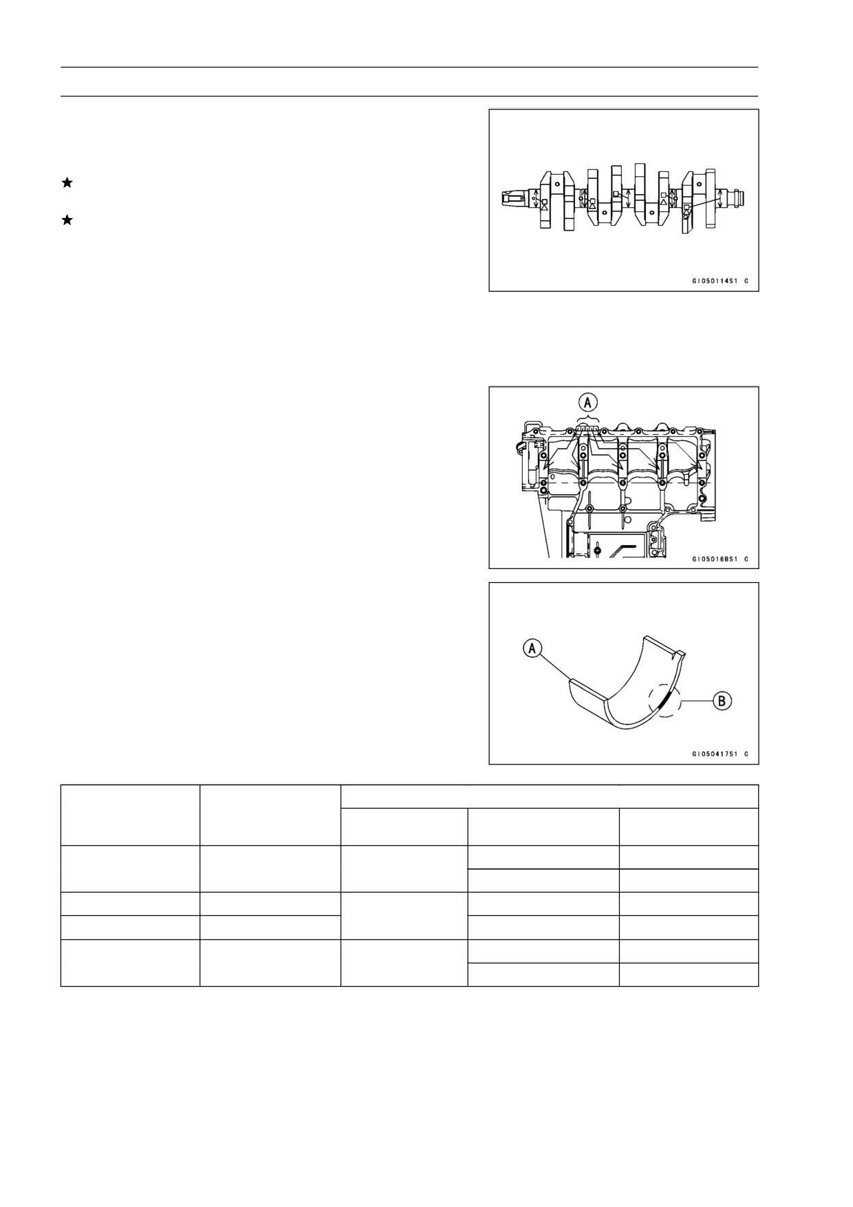
8-16 CRANKSHAFT/TRANSMISSION
Crankshaft and Connecting Rods
Crankshaft Main Journal Diameter
Standard:
29.984 ∼ 30.000 mm (1.1805 ∼ 1.1811 in.)
Service Limit:
29.96 mm (1.1795 in.)
If any journal has worn past the service limit, replace the
crankshaft with a new one.
If the measured journal diameters are not less than the
service limit, but do not coincide with the original diameter
markings on the crankshaft, make new marks on it.
Crankshaft Main Journal Diameter Marks
None
29.984 ∼ 29.994 mm (1.1805 ∼ 1.1809 in.)
1
29.995 ∼ 30.000 mm (1.1809 ∼ 1.1811 in.)
□: Crankshaft Main Journal Diameter Marks, “1” mark
or no mark.
Measure the main bearing bore diameter, and mark the
•
upper crankcase half in accordance with the bore diame-
ter.
○: Crankcase Main Bearing Bore Diameter Marks, “○”
mark or no mark.
NOTE
○Tighten the crankcase bolts to the specified torque (see
Crankcase Assembly).
○The mark already on the upper crankcase half should
almost coincide with the measurement.
Crankcase Main Bearing Bore Diameter Marks
○
33.000 ∼ 33.008 mm (1.2992 ∼ 1.2995 in.)
None
33.009 ∼ 33.016 mm (1.2996 ∼ 1.2998 in.)
Select the proper bearing insert [A] in accordance with the
•
combination of the crankcase and crankshaft coding.
Size Color [B]
Crankcase Main
Crankshaft Main
Bearing Insert*
Bearing Bore
Journal Diameter
Size Color
Part Number
Journal Nos.
Diameter Marking
Marking
92028-1883
3, 5
○
1
Brown
92028-1886
1, 2, 4
None
1
92028-1882
3, 5
Black
○
None
92028-1885
1, 2, 4
92028-1881
3, 5
None
None
Blue
92028-1884
1, 2, 4
*The bearing inserts for Nos. 1, 2 and 4 journals have an oil groove, respectively.
Install the new inserts in the crankcase halves and check
•
insert/journal clearance with the plastigage.
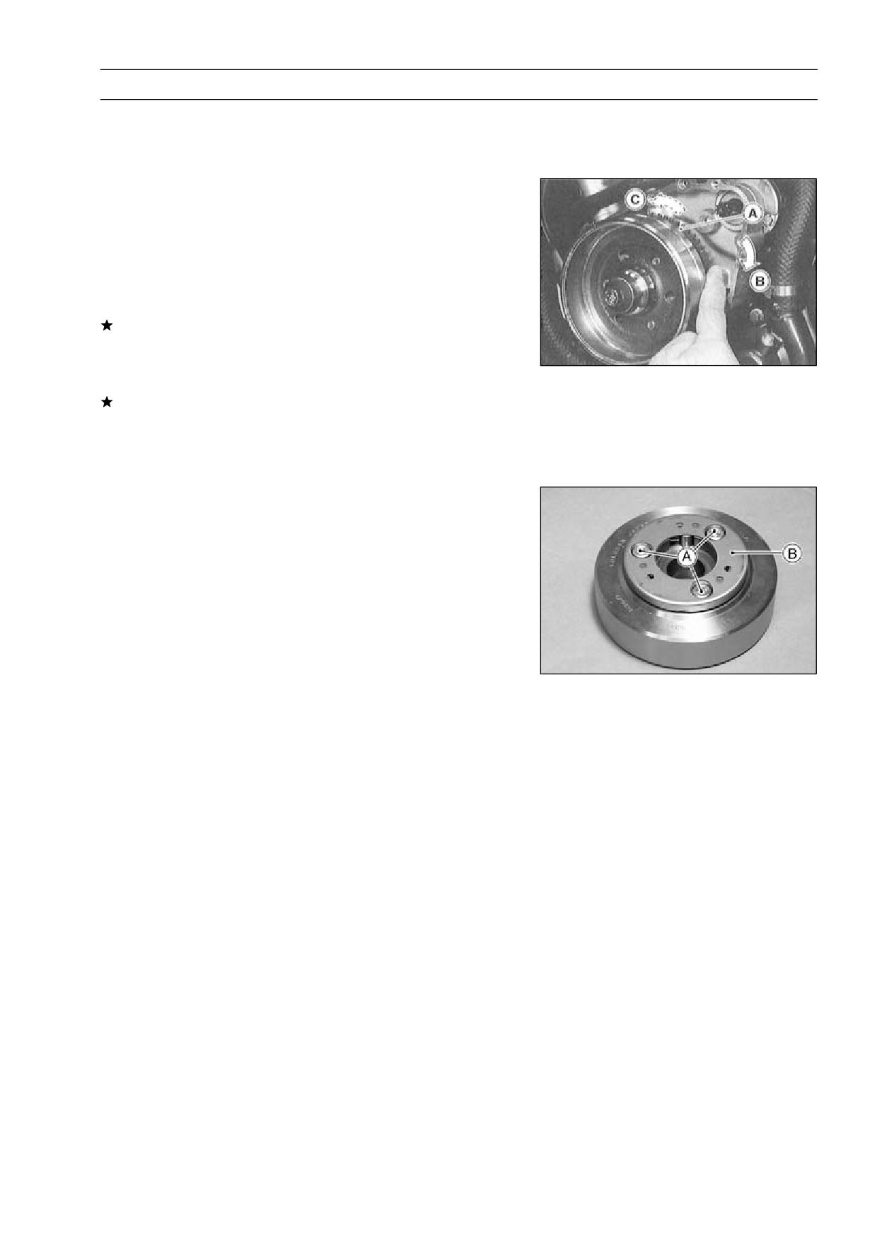
CRANKSHAFT/TRANSMISSION 8-17
Starter Motor Clutch
Starter Motor Clutch Removal/Installation
Refer to the Alternator Rotor Removal and Installation in
•
the Electrical System chapter.
Starter Motor Clutch Inspection
Remove:
•
Alternator Cover (see Electrical System chapter)
Starter Idle Gear
Turn the starter motor clutch gear [a] by hand. The starter
•
motor clutch gear should turn clockwise [B] freely, but
should not turn counterclockwise [C].
If the starter motor clutch does not operate as it should or
if it makes noise, go to the next step.
Disassemble the starter motor clutch, and visually inspect
•
the clutch parts.
If there is any worn or damaged part, replace it.
NOTE
○Examine the starter motor clutch gear as well. Replace
it if is worn or damage.
Starter Motor Clutch Disassembly
Remove:
•
Alternator Rotor (see Electrical System chapter)
Starter Motor Clutch Bolts [A] and Starter Motor Clutch
[B]
Starter Motor Clutch Assembly
Apply a non-permanent locking agent to the threads of
•
the starter motor clutch bolts and tighten them.
Torque - Starter Motor Clutch Bolts: 34 N·m (3.5 kgf·m, 25
ft·lb)
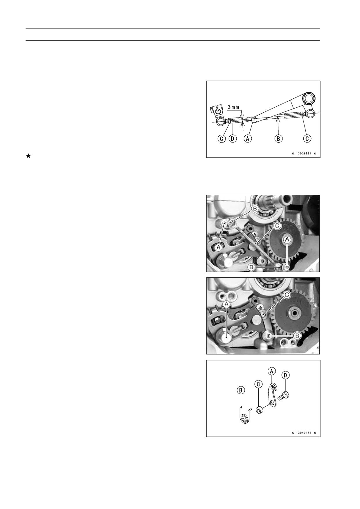
8-18 CRANKSHAFT/TRANSMISSION
Transmission
Shift Pedal Removal
Mark the position of the shift lever on the shift shaft so
•
that it can be installed later in the same position.
Remove the shift lever and shift pedal.
•
Shift Pedal Installation
Install the shift pedal [A] so that the distance between the
•
center of the shift pedal and the center line of the shift rod
[B] is about 3 mm by loosening the front and rear locknuts
[C] and turning the rod.
NOTE
○The locknut next to the groove [D] of the rod has left
-hand threads.
If necessary, adjust the pedal position from the standard
position to suit you as follows.
Loosen the front and rear rod locknuts.
•
Turn the rod to adjust the pedal position.
•
Tighten the locknuts securely.
•
External Shift Mechanism Removal
Remove:
•
Engine Oil (drain, see Engine Lubrication System chap-
ter)
Shift Pedal (see Shift Pedal Removal)
Clutch (see Clutch chapter)
Bolts [A], Oil Pipe Holders [B], Oil Pipe [C] and O-ring
Remove:
•
Shift Shaft [A]
Bolt [B]
Gear Positioning Lever [C] and Spring
External Shift Mechanism Installation
Apply a locking agent to the thread of the gear positioning
•
lever mounting bolt.
Install the gear positioning lever [A] as shown, and tighten
•
the bolt.
Springs [B]
Collar [C]
Bolt [D]
Torque - Gear Positioning Lever Bolt: 12 N·m (1.2 kgf·m,
104 in·lb)
Apply a locking agent to the thread of oil pipe holder bolt.
•
Tighten the oil pipe holder bolts.
•
Torque - Oil Pipe Holder Bolts: 12 N·m (1.2 kgf·m, 104 in·lb)
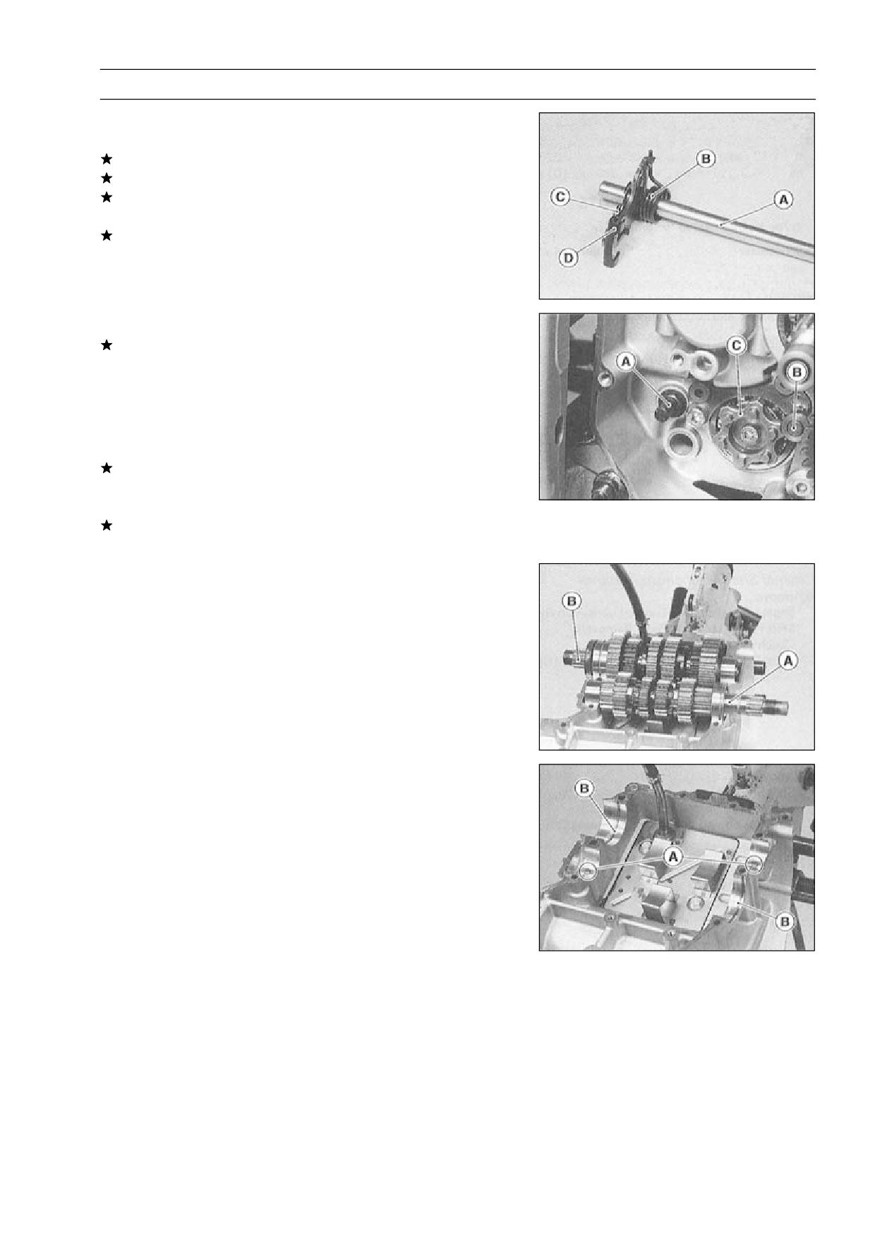
CRANKSHAFT/TRANSMISSION 8-19
Transmission
External Shift Mechanism Inspection
Examine the shift shaft [A] for any damage.
•
If the shaft is bent, straighten or replace it.
If the serration are damaged, replace the shaft.
If the springs [B] [C] are damaged in any way, replace
them.
If the shift mechanism arm [D] is damaged in any way,
replace the arm.
Check the return spring pin [A] is not loose.
•
If it is loose, unscrew it, apply a non-permanent locking
agent to the threads, and tighten it.
Torque - Shift Shaft Return Spring Pin: 28 N·m (2.9 kgf·m,
21 ft·lb)
Check the gear positioning lever [B] and it’s spring for
•
breaks or distortion.
If the lever or spring are damaged in any way, replace
them.
Visually inspect the shift drum cam [C].
•
If they are badly worn or if they show any damage, replace
it.
Transmission Shaft Removal
Split the crankcase (see Crankcase Splitting).
•
Remove the drive shaft [A] and output shaft [B].
•
Transmission Shaft Installation
Check to see that the set pins [A] and set rings [B] are in
•
place.
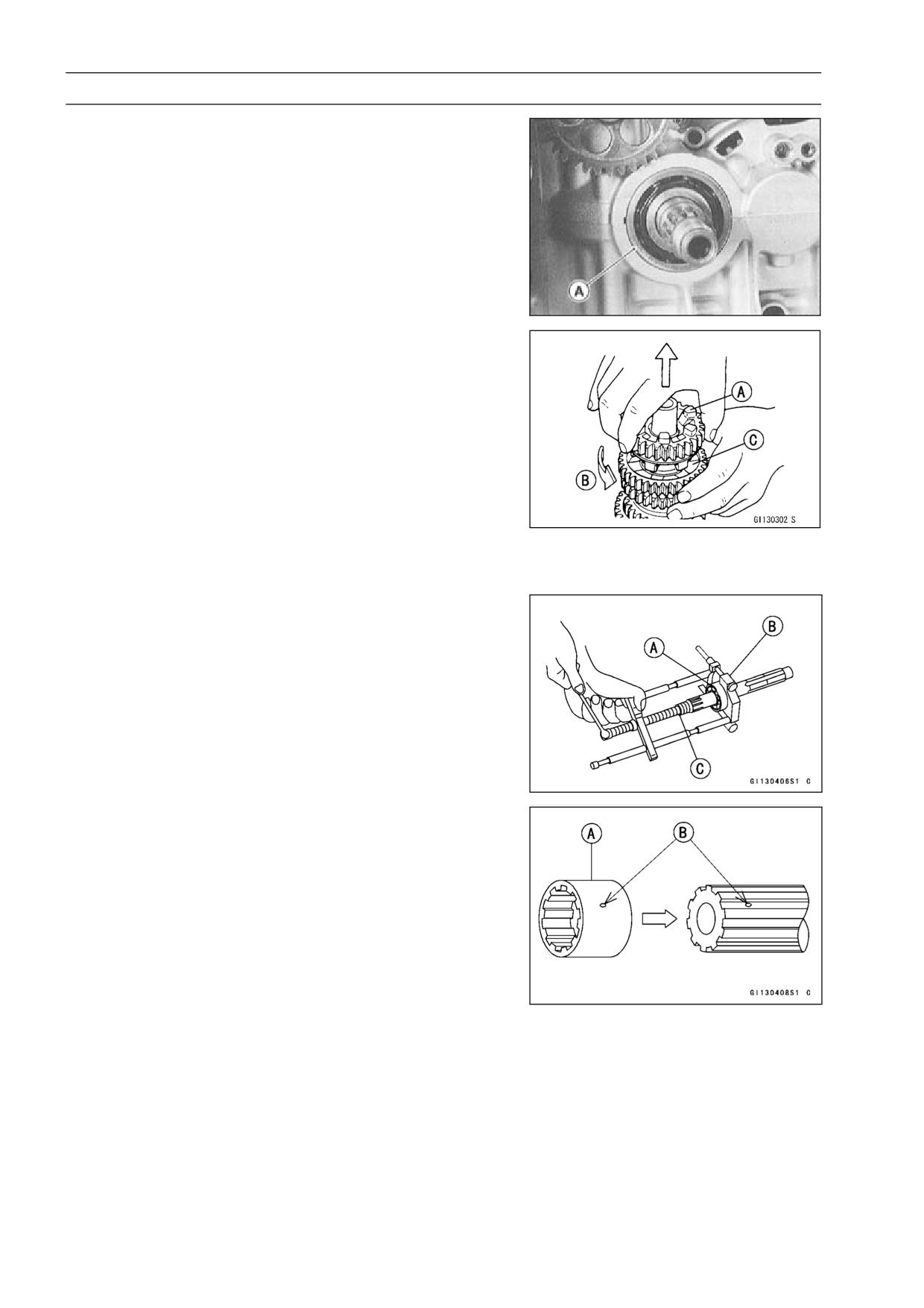
8-20 CRANKSHAFT/TRANSMISSION
Transmission
Install the drive shaft and output shaft into the upper
•
crankcase half.
Apply engine oil to the sliding surfaces of the gears and
•
bearings.
○The bearing set pins and rings must match properly with
the holes or grooves in the bearing outer races. When
they are properly matched, there is no clearance between
the crankcase and the bearing outer races [A].
Transmission Shaft Disassembly
Remove the transmission shafts (see Transmission Shaft
•
Removal).
Remove the circlips, disassemble the transmission
•
shafts.
Special Tool - Outside Circlip Pliers: 57001-144
The 5th gear [A] on the output shaft has three steel balls
•
assembled into it for the positive neutral finder mecha-
nism. Remove the 5th gear.
○Set the output shaft in a vertical position holding the 3rd
gear [B].
○Spin the 5th gear quickly [C] and pull it off upward.
Remove the ball bearing [A] from each shafts.
•
Special Tools - Bearing Puller: 57001-135 [B]
Bearing Puller Adapter: 57001-317 [C]
Discard the bearing.
•
Transmission Shaft Assembly
Install the ball bearing on the drive shaft with the groove
•
toward the clutch side.
Install the gear bushing [A] on the shafts with their oil
•
holes [B] aligned.
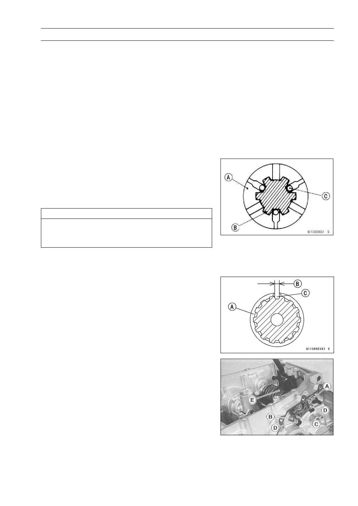
CRANKSHAFT/TRANSMISSION 8-21
Transmission
The drive shaft gears can be recognized by size: the gear
•
with the smallest diameter is 1st gear, and the largest one
is 6th gear. Be sure that all parts are put back in the cor-
rect sequence and all circlips and washers are properly in
place.
Install the 3rd/4th gear onto the drive shaft with their holes
•
aligned.
The output shaft gears can be recognized by size: the
•
gear with the largest diameter is 1st gear, and the small-
est one is 6th gear. Be sure that all parts are put back
in the correct sequence and all circlips and washers are
properly in place.
Install the 5th and 6th gears onto the output shaft with
•
their holes aligned.
Fit the steel balls into the 5th gear holes in the output shaft
•
as shown.
View A - A’ (see CRANKSHAFT/TRANSMISSION 8-24)
[A] Gear (5th)
[B] Shaft
[C] Steel Balls
CAUTION
Do not apply grease to the steel balls to hold them
in place. This will cause the positive neutral finder
mechanism to malfunction.
○Check the ball-locking effect that the 5th gear does not
come out of the output shaft when moving it up and down
by hand.
Replace any circlip that were removed with new ones.
•
Install the circlips [A] so that opening [B] is aligned with a
•
spline groove [C].
Check that each gear spins or slides freely on the trans-
•
mission shafts without binding after assembly.
Shift Drum and Fork Removal
Remove:
•
Clutch (see Clutch chapter)
Oil Pan (see Engine Lubrication System chapter)
External Shift Mechanism (see External Shift Mecha-
nism Removal)
Gear Positioning Lever
Bolt [A] and Screw [B]
Shift Drum Bearing Holder [C]
Pull out the shift rods [D], and take off the shift forks.
•
Pull out the shift drum [E].
•
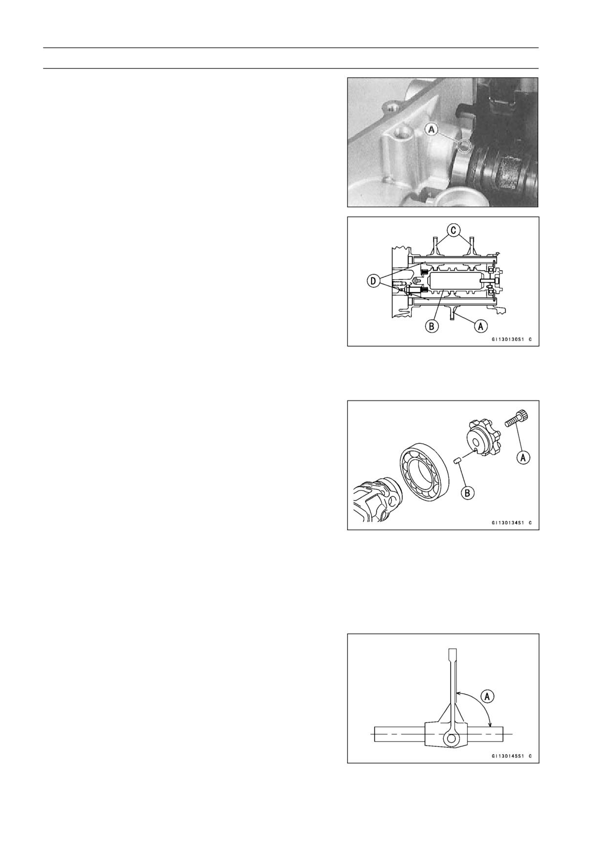
8-22 CRANKSHAFT/TRANSMISSION
Transmission
Shift Drum and Fork Installation
Set the transmission gears in the neutral position.
•
Install the shift drum so that the punch mark [A] on it faces
•
oil pan side.
Install the forks as shown.
•
Position the one with shortest ears [A] on the drive shaft
•
and place the pin in the center groove in the shift drum
[B].
○The two forks [C] on the output shaft are identical.
Install the shift rods [D], noting the groove position. The
•
rods are identical.
Apply a non-permanent locking agent to the threads of the
•
shift drum bearing holder screw, and tighten it and bolt.
Torque - Shift Drum Bearing Holder Bolt: 12 N·m (1.2 kgf·m,
104 in·lb)
Shift Drum Bearing Holder Screw: 4.9 N·m (0.5
kgf·m, 43 in·lb)
Shift Drum Disassembly
Remove the shift drum (see Shift Drum and Fork Re-
•
moval).
While holding the shift drum with a vise, remove the shift
•
drum cam holder bolt.
[A] Shift Drum Cam Holder Bolt
[B] Dowel Pin
Shift Drum Assembly
Be sure to install the dowel pin.
•
Apply a non-permanent locking agent to the threads of
•
the shift drum cam holder bolt, and tighten it.
Torque - Shift Drum Cam Holder Bolt: 12 N·m (1.2 kgf·m,
104 in·lb)
Shift Fork Bending Inspection
Visually inspect the shift forks, and replace any fork that is
•
bent. A bent fork could cause difficulty in shifting, or allow
the transmission to jump out of gear when under power.
90° [A]
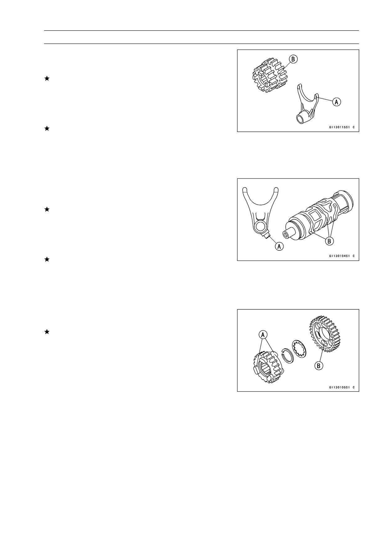
CRANKSHAFT/TRANSMISSION 8-23
Transmission
Shift Fork/Gear Groove Wear Inspection
Measure the thickness of the shift fork ears [A], and mea-
•
sure the width [B] of the gear grooves.
If the thickness of a shift fork ear is less than the service
limit, the shift fork must be replaced.
Shift Fork Ear Thickness
Standard:
5.9 ∼ 6.0 mm (0.2323 ∼ 0.2362 in.)
Service Limit:
5.8 mm (0.228 in.)
If the gear groove is worn over the service limit, the gear
must be replaced.
Gear Groove Width
Standard:
6.05 ∼ 6.15 mm (0.2382 ∼ 0.2421 in.)
Service Limit:
6.25 mm (0.246 in.)
Shift Fork Guide Pin/Drum Groove Wear Inspection
Measure the diameter of each shift fork guide pin [A], and
•
measure the width [B] of each shift drum groove.
If the guide pin on any shift fork is less than the service
limit, the fork must be replaced.
Shift Fork Guide Pin Diameter
Standard:
5.9 ∼ 6.0 mm (0.2323 ∼ 0.2362 in.)
Service Limit:
5.8 mm (0.228 in.)
If any shift drum groove is worn over the service limit, the
drum must be replaced.
Shift Drum Groove Width
Standard:
6.05 ∼ 6.20 mm (0.2382 ∼ 0.2441 in.)
Service Limit:
6.30 mm (0.248 in.)
Gear Dog and Gear Dog Hole Damage Inspection
Visually inspect the gear dogs [A] and gear dog holes [B].
•
Replace any damaged gears or gears with excessively
worn dogs or dog holes.
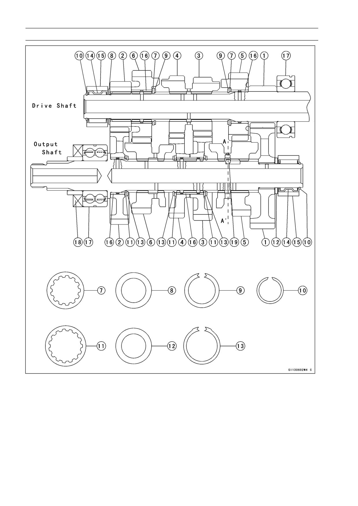
8-24 CRANKSHAFT/TRANSMISSION
Transmission
1. 1st Gear
11. Toothed Washer
2. 2nd Gear
12. Thrust Washer
3. 3rd Gear
13. Circlip
4. 4th Gear
14. Needle Bearing
5. 5th Gear
15. Bearing Outer Race
6. 6th (Top) Gear
16. Bushing
7. Toothed Washer
17. Ball Bearing
8. Thrust Washer (Thin)
18. Oil Seal
9. Circlip
19. Steel Ball
10. Circlip
WHEELS/TIRES 9-1
Wheels/Tires
Table of Contents
Exploded View
9-2
Specifications
9-3
Wheels (Rims)
9-4
Front Wheel Removal
9-4
Front Wheel Installation
9-4
Rear Wheel Removal
9-5
Rear Wheel Installation
9-6
Wheel Inspection
9-7
Axle Inspection
9-7
Balance Inspection
9-7
Balance Adjustment
9-8
Balance Weight Removal
9-8
Balance Weight Installation
9-8
9
Tires
9-11
Air Pressure Inspection/Adjustment
9-11
Tire Inspection
9-11
Tire Removal
9-12
Tire Installation
9-12
Tire Repair
9-14
Hub Bearing
9-15
Hub Bearing Removal
9-15
Hub Bearing Installation
9-15
Hub Bearing Inspection
9-16
Hub Bearing Lubrication
9-16
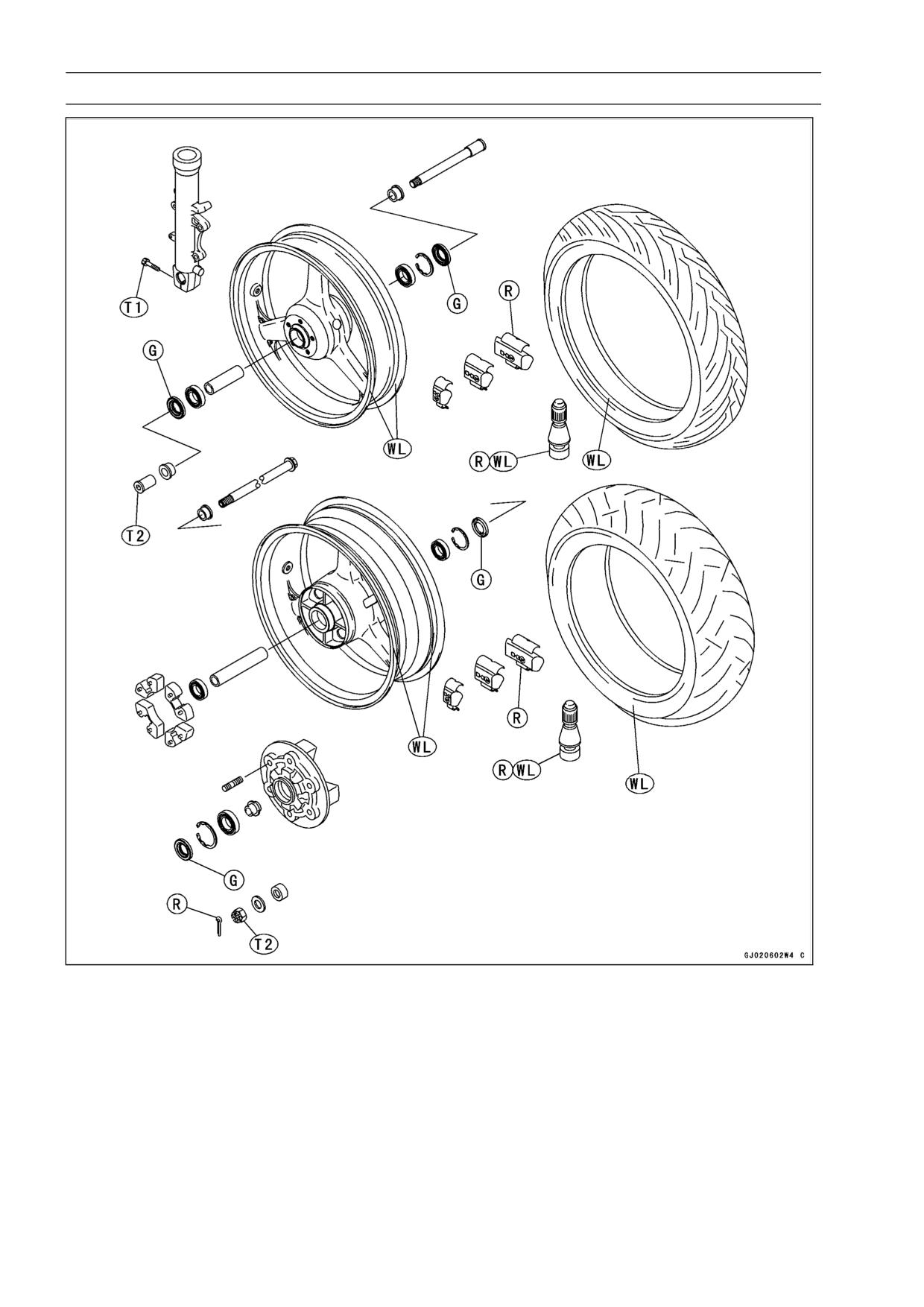
9-2 WHEELS/TIRES
Exploded View
T1: 20 N·m (2.0 kgf·m, 14.5 ft·lb)
T2: 127 N·m (13 kgf·m, 94 ft·lb)
G: Apply grease.
R: Replacement Parts
WL: Apply soap and water solution or rubber lubricant.
WHEELS/TIRES 9-3
Specifications
Item
Standard
Service Limit
Wheels (Rims)
Rim Size:
Front
J17M/C × MT3.50
- - -
Rear
J17 × MT5.50
- - -
Rim runout:
Axial
TIR 0.5 mm (0.020 in.) or less
TIR 1 mm (0.040 in.)
Radial
TIR 0.8 mm (0.031 in.) or less
TIR 1 mm (0.040 in.)
Axle runout/100 mm (3.9 in.)
0.05 mm (0.002 in.) or less
0.2 mm (0.008 in.)
Wheel balance
10 g (0.35 oz) or less
- - -
10 g (0.35 oz), 20 g (0.70 oz), 30 g
Balance weights
- - -
(1.05 oz)
Tires
Air pressure: (when cold)
Front
Up to 182 kg (401 lb) load: 250 kPa
- - -
(2.5 kgf/cm² 36 psi)
Rear
Up to 182 kg (401 lb) load: 290 kPa
- - -
(2.9 kgf/cm², 41 psi)
Tread depth:
Front
DUNLOP:
4.0 mm (0.16 in.)
1 mm (0.04 in.)
MICHELIN:
3.8 mm (0.15 in.)
(DE) 1.6 mm (0.06 in.)
Rear
DUNLOP:
5.4 mm (0.21 in.)
Up to 130 km/h
MICHELIN:
5.6 mm (0.22 in.)
(80 mph): 2 mm (0.08 in.)
Over 130 km/h
(80 mph): 3 mm (0.12 in.)
Standard tires:
Make, Type
Size
Front
DUNLOP, D207F
120/65 ZR17 (56 W)
(ZX600-J1 ∼ J2)
MICHELIN Pilot SPORT M
120/65 ZR17 M/C (56
BRIDGESTONE, BATTLAX BT010F
W) (ZX600-J3 ∼)
RADIAL
PIRELLI, MTR21 Corsa
METZELER, MEZ3 Front Racing
Rear
DUNLOP, D207T
180/55 ZR17 (73 W)
(ZX600-J1 ∼ J2)
MICHELIN Pilot SPORT M
180/55 ZR17 M/C (73
BRIDGESTONE, BATTLAX BT010R
W) (ZX600-J3 ∼)
RADIAL G
PIRELLI, MTR22 Corsa
METZELER, MEZ3 Racing
DE: Germany
Special Tools - Jack: 57001-1238
Inside Circlip Pliers: 57001-143
Bearing Driver Set: 57001-1129
Bearing Remover Shaft,
13: 57001-1377
Bearing Remover Head,
25 ×
28: 57001-1346
WARNING
Use the same manufacturer’s tires on both front and rear wheels.
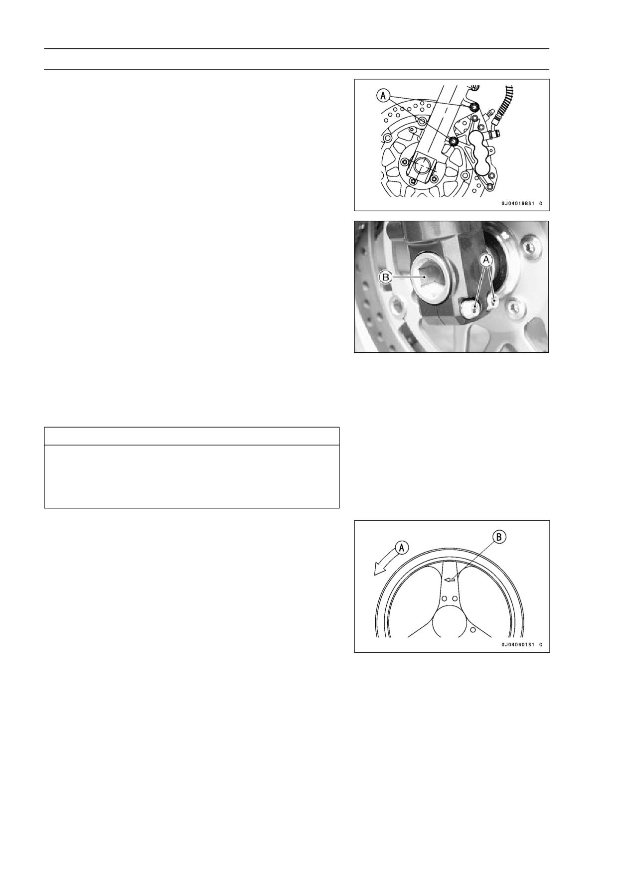
9-4 WHEELS/TIRES
Wheels (Rims)
Front Wheel Removal
Remove:
•
Lower Fairing (see Frame chapter)
Brake Caliper Mounting Bolts [A]
Loosen:
•
Right Side Axle Clamp Bolts [A]
Axle [B]
Raise the front wheel off the ground.
•
Special Tool - Jack: 57001-1238
Pull out the axle to the right and drop the front wheel out
•
of the forks.
CAUTION
Do not lay the wheel down on one of the discs. This
can damage or warp the disc. Place blocks un-
der the wheel so that the disc does not touch the
ground.
Front Wheel Installation
NOTE
○The direction of the wheel rotation [A] is shown by an
arrow [B] on the wheel spoke.
Check the wheel rotation mark on the front wheel and
•
install it.
Fit the collars on the both sides of the hub.
•
Tighten the axle nut.
•
Torque - Front Axle Nut: 127 N·m (13 kg·m, 94 ft·lb)
Before tightening the clamp bolts on the right front fork
•
leg, pump the front fork up and down 4 or 5 times to all on
the right front fork leg to seat on the front axle.
NOTE
○Put a block in front of the front wheel to stop moving.
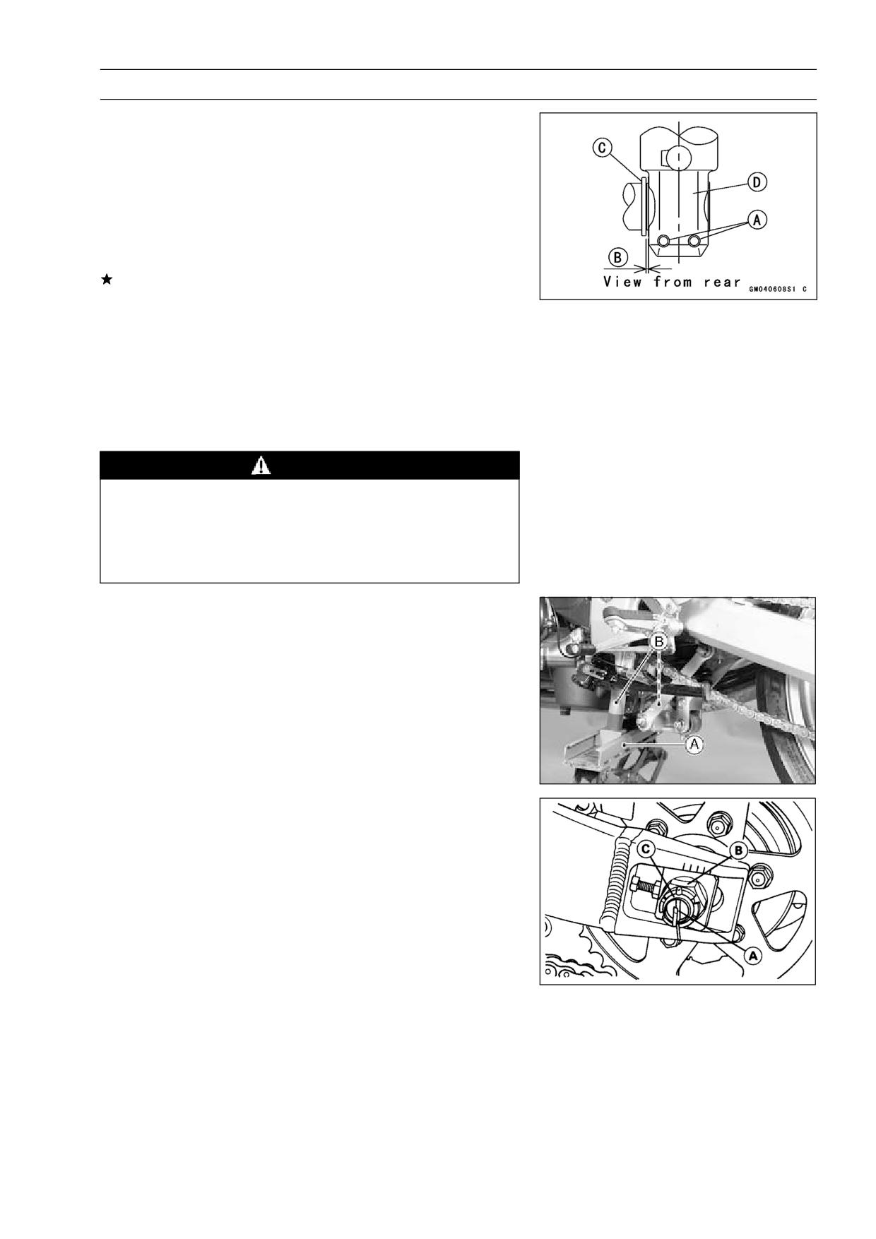
WHEELS/TIRES 9-5
Wheels (Rims)
Tighten the axle clamp bolts [A] on the right fork leg first.
•
Torque - Front Axle Clamp Bolts: 20 N·m (2.0 kg·m, 14.5
ft·lb)
Check the clearance [B] between the right fork leg [D] and
•
collar [C] with the thickness gauge.
Standard:
1.5 mm (0.06 in.)
Usable range:
0.5 ∼ 2.8 mm (0.02 ∼ 0.11 in.)
If the clearance is out of this range, remove the front wheel
again and check the axle, wheel hub and other related
parts for damage.
Tighten the axle clamp bolts on the left fork leg.
•
Torque - Front Axle Clamp Bolts: 20 N·m (2.0 kg·m, 14.5
ft·lb)
Install the front brake calipers (see Brakes chapter).
•
Check the front brake effectiveness (see Brakes chapter).
•
WARNING
Do not attempt to drive the motorcycle until a full
brake lever is obtained by pumping the brake lever
until the pads are against the disc. The brake will
not function on the first application of the lever if
this is not done.
Rear Wheel Removal
Remove the lower fairings (see Frame chapter).
•
Using the jack [A], raise the rear wheel off the ground.
•
○Adjust the length of the jack legs [B], situate the motorcy-
cle so that it is perpendicular to the ground.
Special Tool - Jack: 57001-1238
Remove:
•
Cotter Pin [A]
Axle Nut [B]
Axle [C]
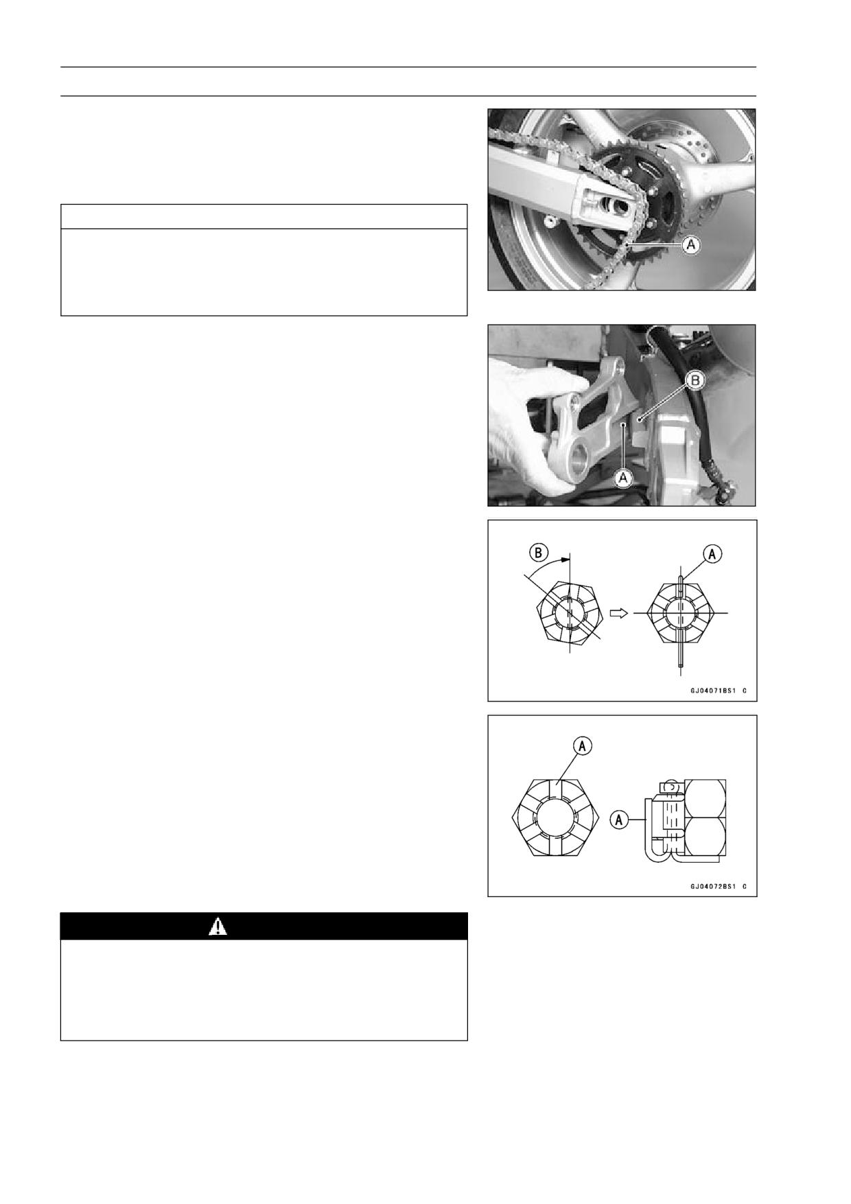
9-6 WHEELS/TIRES
Wheels (Rims)
Remove the rear caliper.
•
Remove the chain cover.
•
Remove the drive chain [A] from the rear sprocket toward
•
the left.
Move the rear wheel back and remove it.
•
CAUTION
Do not lay the wheel on the ground with the disc
facing down. This can damage or warp the disc.
Place blocks under the wheel so that the disc does
not touch the ground.
Rear Wheel Installation
Engage the drive chain with the rear sprocket.
•
Install the caliper bracket [A] onto the swingarm stop [B].
•
○Insert the axle from the right side of the wheel, and tighten
the axle nut.
Torque - Rear Axle Nut: 127 N·m (13 kg·m, 94 ft·lb)
Install a new cotter pin.
•
NOTE
○When inserting the cotter pin, if the slots in the nut do
not align with the cotter pin hole in the axle, tighten the
nut clockwise [B] up to next alignment.
○It should be within 30 degree.
○Loosen once and tighten again when the slot goes past
the nearest hole.
Bend the cotter pin [A] over the nut.
•
Adjust the drive chain slack after installation (see Final
•
Drive chapter).
Install the rear caliper and the chain cover.
•
Check the rear brake effectiveness.
•
WARNING
Do not attempt to drive the motorcycle until a full
brake pedal is obtained by pumping the brake pedal
until the pads are against the disc. The brake will
not function on the first application of the pedal if
this is not done.
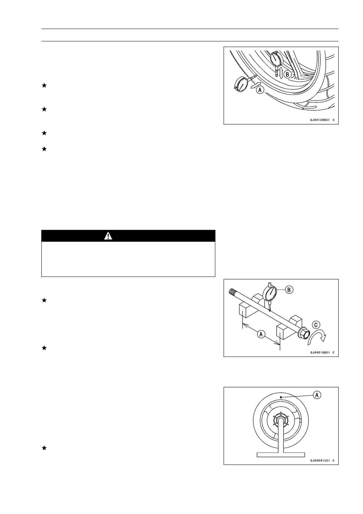
WHEELS/TIRES 9-7
Wheels (Rims)
Wheel Inspection
Raise the front/rear wheel off the ground.
•
Special Tool - Jack: 57001-1238
Spin the wheel lightly, and check for roughness or binding.
•
If roughness or binding is found, replace the hub bearings.
Inspect the wheel for small cracks, dents, bending, or
•
warp.
If there is any damage to the wheel, replace the wheel.
Measure the rim runout, radial [B] and axial [A], with a dial
•
gauge with tire installed.
If the rim runout exceeds the service limit, check the hub
bearings.
If the problem is not due to the bearings, replace the
wheel.
Rim Runout (with tire installed)
Standard:
Axial
TIR 0.5 mm (0.02 in.) or less
Radial
TIR 0.8 mm (0.03 in.) or less
Service Limit:
Axial
TIR 1 mm (0.04 in.)
Radial
TIR 1 mm (0.04 in.)
WARNING
Never attempt to repair a damaged wheel. If there
is any damage besides wheel bearings, the wheel
must be replaced to insure safe operational condi-
tion.
Axle Inspection
Visually inspect the front and rear axle for damages.
•
If the axle is damaged or bent, replace it.
Place the axle in V blocks that are 100 mm (3.94 in.) [A]
•
apart, and set a dial gauge [B] on the axle at a point
halfway between the blocks. Turn [C] the axle to mea-
sure the runout. The difference between the highest and
lowest dial readings is the amount of runout.
If axle runout exceeds the service limit, replace the axle.
Axle Runout/100 mm (3.94 in.)
Standard:
0.05 mm (0.002 in.) or less
Service Limit: 0.2 mm (0.08 in.)
Balance Inspection
Remove the wheel.
•
Support the wheel so that it can be spun freely.
•
Spin the wheel lightly, and mark [A] the wheel at the top
•
when the wheel stops.
○Repeat this procedure several times. If the wheel stops
of its own accord in various positions, it is well balanced.
If the wheel always stops in one position, adjust the wheel
balance.
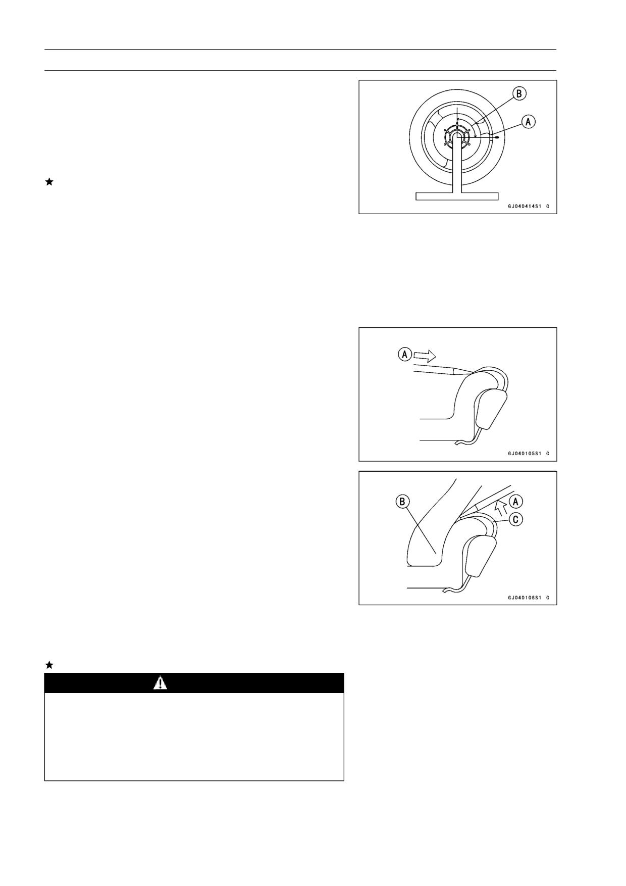
9-8 WHEELS/TIRES
Wheels (Rims)
Balance Adjustment
If the wheel always stops in one position, provisionally
•
attach a balance weight [A] on the rim at the marking using
adhesive tape.
Rotate the wheel 1/4 turn [B], and see whether or not the
•
wheel stops in this position. If it does, the correct balance
weight is being used.
If the wheel rotates and the weight goes up, replace the
weight with the next heavier size. If the wheel rotates and
the weight goes down, replace the weight with the next
lighter size. Repeat these steps until the wheel remains
at rest after being rotated 1/4 turn.
Rotate the wheel another 1/4 turn and then another 1/4
•
turn to see if the wheel is correctly balanced.
Repeat the entire procedure as many times as necessary
•
to achieve correct wheel balance.
Permanently install the balance weight.
•
Balance Weight Removal
When the tire is not on the rim.
Push [A] the blade portion toward the outside with a reg-
•
ular tip screw driver, and slip the weight off the rim flange.
Discard the used balance weight.
•
When the tire is on the rim.
Pry [A] the balance weight off the rim flange using a reg-
•
ular tip screw driver as shown in the figure.
○Insert a tip of the screw driver between the tire bead [B]
and weight blade [C] until the end of the tip reaches the
end of the weight blade.
○Push the driver grip toward the tire so that the balance
weight slips off the rim flange.
Discard the used balance weight.
•
Balance Weight Installation
Check if the weight portion has any play on the blade and
•
clip.
If it does, discard it.
WARNING
If the balance weight has any play on the rim flange,
the blade and/or clip have been stretched. Replace
the loose balance weight.
Do not reuse used balance weight.
Unbalanced wheels can create an unsafe riding
condition.
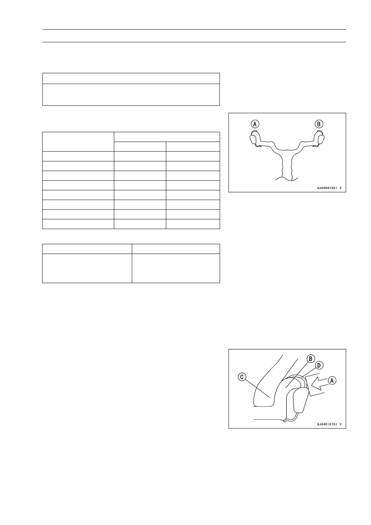
WHEELS/TIRES 9-9
Wheels (Rims)
Lubricate the balance weight blade, tire bead, and rim
•
flange with a soap and water solution or rubber lubricant.
This helps the balance weight slip onto the rim flange.
CAUTION
Never lubricate with engine oil or petroleum distil-
lates because they will deteriorate the tire.
When required total weight exceeds 20 g, install balance
•
weight at both sides of rim flange as shown.
Weight Selection
Required Total Weight
One Side [A]
Other Side [B]
20 g
10 g
10 g
30 g
20 g
10 g
40 g
20 g
20 g
50 g
30 g
20 g
60 g
30 g
30 g
70 g
20 g + 20 g
30 g
80 g
20 g + 20 g
20 g + 20 g
90 g
20 g + 30 g
20 g + 20 g
Balance Weight
Part Number
Weight (grams)
41075-1014
10 (0.35 oz)
41075-1015
20 (0.70 oz)
41075-1016
30 (1.05 oz)
NOTE
○Balance weights are available from Kawasaki dealers in
10, 20, and 30 gram sizes. An imbalance of less than
10 grams will not usually affect running stability.
○Do not use four or more balance weight (more than 90
gram). If the wheel requires an excess balance weight,
disassemble the wheel to find the cause.
Install the balance weight on the rim.
•
○Slip the weight on the rim flange by pushing or lightly ham-
mering the weight in the direction shown in the figure.
Push or Hammer [A]
Rim Flange [B]
Tire Bead [C]
Blade [D]
9-10 WHEELS/TIRES
Wheels (Rims)
○Check that the blade [A] and weight [B] seat fully on the
rim flange [C], and that the clip [D] is hooked over the rim
ridge [E] and reaches rim flat portion.
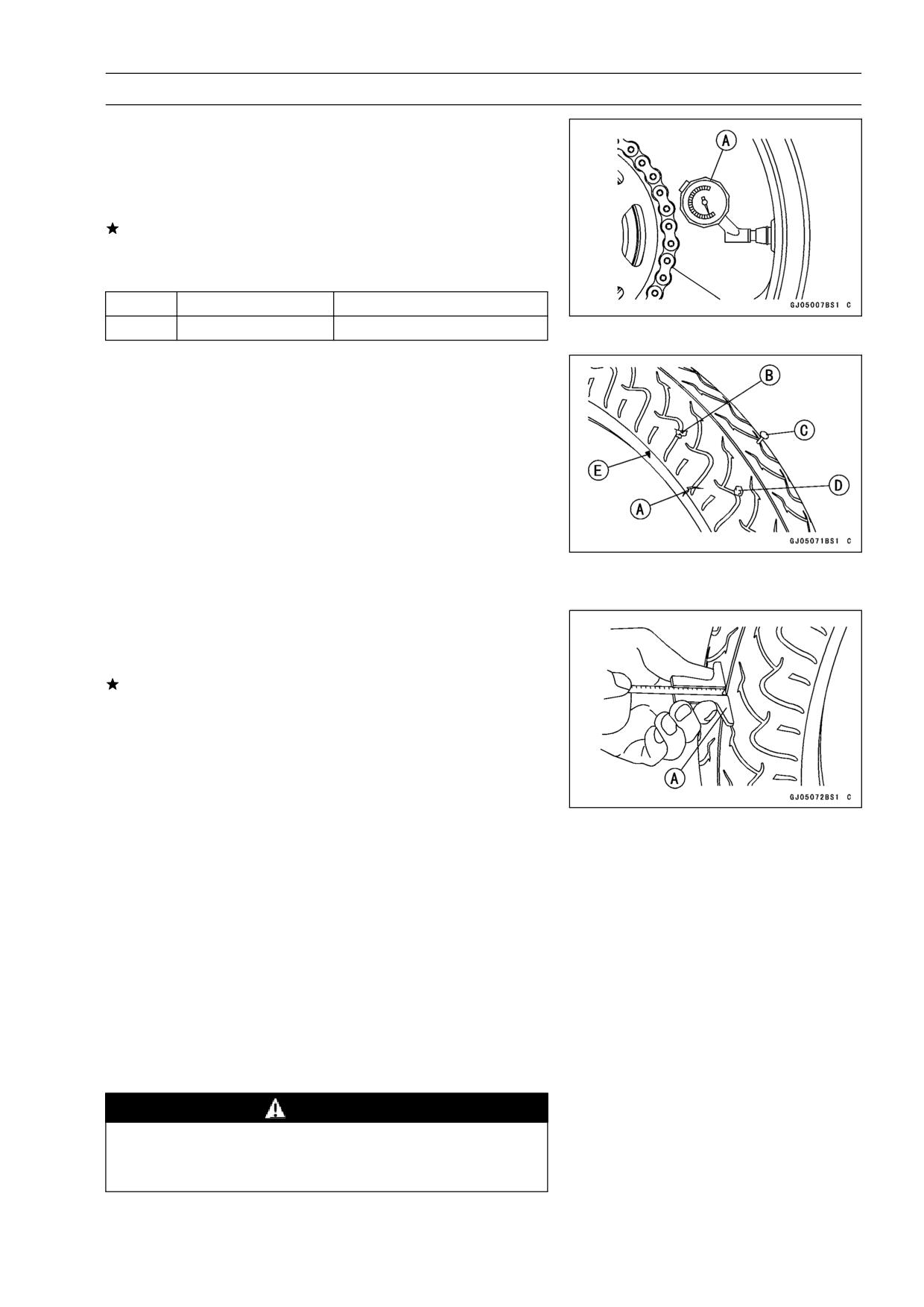
WHEELS/TIRES 9-11
Tires
Air Pressure Inspection/Adjustment
Measure the tire air pressure with an air pressure gauge
•
[A] when the tires are cold (that is, when the motorcycle
has not been ridden more than a mile during the past 3
hours).
Adjust the tire air pressure according to the specifications
if necessary.
Air Pressure (when cold)
Front
Up to 182 kg (401 lb)
250 kPa (2.5 kgf/cm², 36 psi)
Rear
Up to 182 kg (401 lb)
290 kPa (2.9 kgf/cm², 41 psi)
Tire Inspection
As the tire tread wears down, the tire becomes more sus-
ceptible to puncture and failure. An accepted estimate is
that 90% of all tire failures occur during the last 10% of tread
life (90% worn). So it is false economy and unsafe to use
the tires until they are bald.
Visually inspect the tire for cracks [A] and cuts [B], re-
•
placing the tire in case of damage. Swelling or high spots
indicate internal damage, requiring tire replacement.
Remove any imbedded stones [D], nail [C] or other foreign
•
particles from the tread.
Wear Indicator [E]
Measure the tread depth at the center of the tread with a
•
depth gauge [A]. Since the tire may wear unevenly, take
measurement at several places.
If any measurement is less than the service limit, replace
the tire.
Tread Depth
Standard:
Front
4.0 mm (0.16 in.) (DUNLOP),
3.8 mm (0.15 in.) (MICHELIN)
Rear
5.4 mm (0.21 in.) (DUNLOP)
5.6 mm (0.22 in.) (MICHELIN)
Service Limit:
Front
1 mm (0.04 in.), (DE) 1.6 mm (0.06 in.)
2 mm (0.08 in.) (Up to 130 km/h (80
Rear
mph))
3 mm (0.12 in.) (Over 130 km/h (80 mph))
WARNING
To ensure safe handling and stability, use only the
recommended standard tires for replacement, in-
flated to the standard pressure.
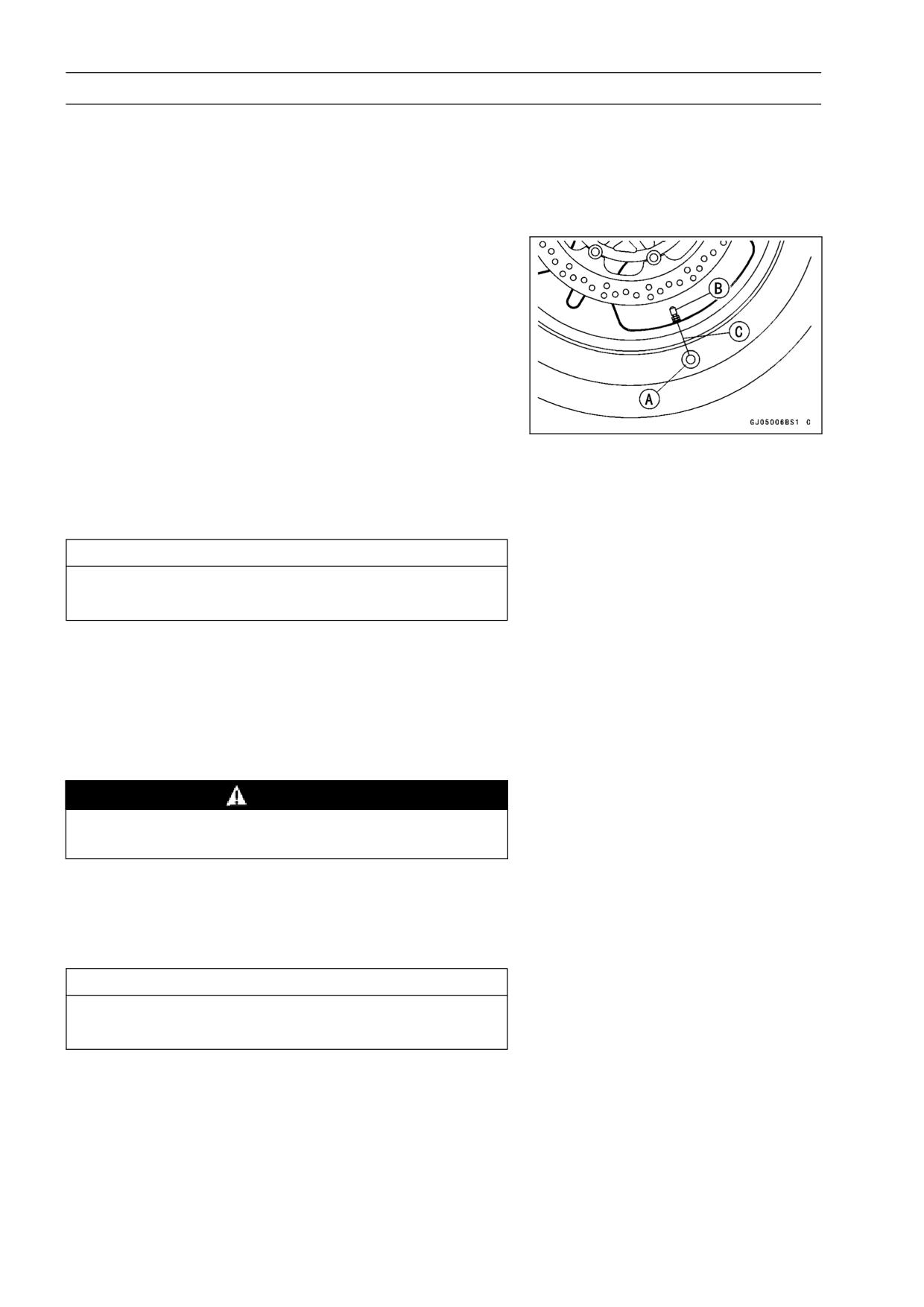
9-12 WHEELS/TIRES
Tires
NOTE
○Most countries may have their own regulations a mini-
mum tire tread depth: be sure to follow them.
○Check and balance the wheel when a tire is replaced
with a new one.
Tire Removal
Remove:
•
Wheel (see Front, Rear Wheels Removal)
Disc(s)
Valve Core (let out the air)
To maintain wheel balance, mark the air valve position on
•
the tire with chalk so that the tire can be reinstalled in the
same position.
Chalk Mark or Yellow Mark [A]
Air Valve [B]
Align [C]
Lubricate the tire beads and rim flanges on both sides with
•
a soap and water solution or rubber lubricant. This helps
the tire beads slip off the rim flanges.
CAUTION
Never lubricate with engine oil or petroleum distil-
lates because they will deteriorate the tire.
Remove the tire from the rim using a suitable commer-
•
cially available tire changer.
NOTE
○The tires cannot be removed with hand tools because
they fit the rims too tightly.
Tire Installation
WARNING
Use the same manufacture’s on both front and rear
wheels.
Inspect the rim and tire, and replace them if necessary.
•
Clean the sealing surfaces of the rim and tire, and smooth
•
the sealing surfaces of the rim with a fine emery cloth if
necessary.
Remove the air valve and discard it.
•
CAUTION
Replace the air valve whenever the tire is replaced.
Do not reuse the air valve.
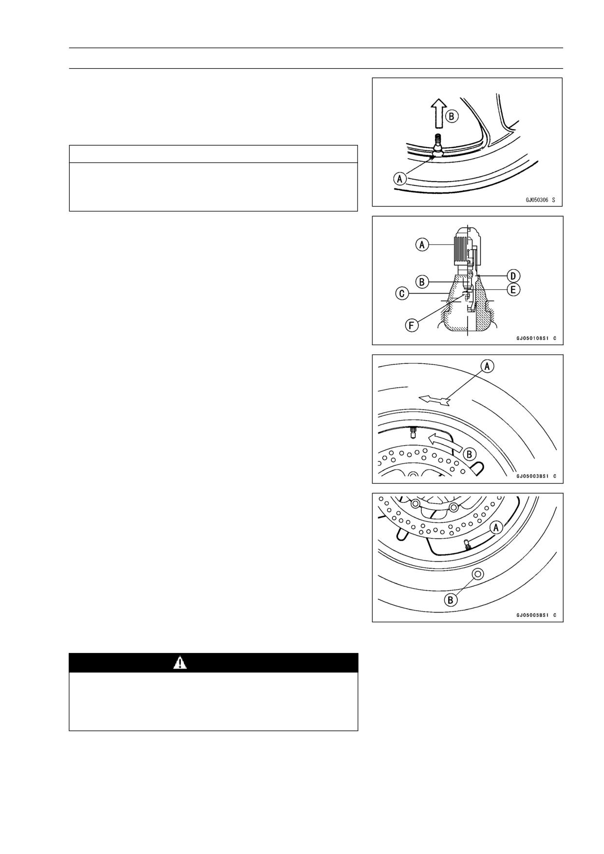
WHEELS/TIRES 9-13
Tires
Install a new valve in the rim.
•
○Remove the valve cap, lubricate the stem seal [A] with a
soap and water solution or rubber lubricant, and pull [B]
the air valve [A] through the rim from the inside out until it
snaps into place.
CAUTION
Do not use engine oil or petroleum distillates to lu-
bricate the stem because they will deteriorate the
rubber.
○The air valve is shown in the figure.
[A] Valve Cap
[B] Valve Core
[C] Stem Seal
[D] Valve Stem
[E] Valve Seat
[F] Valve Opened
Apply a soap and water solution, or rubber lubricant to the
•
rim flange and tire beads.
Check the tire rotation mark on the front and rear tires and
•
install them on the rim accordingly.
Tire Rotation Mark [A]
Rotating Direction [B]
Position the tire on the rim so that the air valve [A] is at
•
the tire balance mark [B] (the chalk mark made during
removal, or the yellow paint mark on a new tire).
Install the tire bead over the rim flange using a suitable
•
commercially available tire changer.
Lubricate the tire beads and rim flanges with a soap and
•
water solution or rubber lubricant to help seat the tire
beads in the sealing surfaces of the rim while inflating the
tire.
Center the rim in the tire beads, and inflate the tire with
•
compressed air until the tire beads seat in the sealing
surfaces.
WARNING
Be sure to install the valve core whenever inflating
the tire, and do not inflate the tire to more than 400
kPa (4.0 kg/cm², 57 psi). Overinflation can explode
the tire with possibility of injury and loss of life.
9-14 WHEELS/TIRES
Tires
Check to see that the rim lines [A] on both sides of the tire
•
sidewalls are parallel with the rim flanges.
If the rim flanges and tire sidewall rim lines are not parallel,
remove the valve core.
Lubricate the rim flanges and tire beads.
•
Install the valve core and inflate the tire again.
•
After the tire beads seat in the rim flanges, check for air
•
leakage.
○Inflate the tire slightly above standard inflation.
○Use a soap and water solution or submerge the tire, and
check for bubbles that would indicate leakage.
Adjust the air pressure to the specified pressure (see Tire
•
Inspection).
Install the brake disc(s) so that the marked side faces out
•
(see Brakes chapter).
Adjust the wheel balance.
•
Tire Repair
Currently two types of repair for tubeless tires have come
into wide use. One type is called a temporary (external) re-
pair which can be carried out without removing the tire from
the rim, and the other type is called permanent (internal)
repair which requires tire removal. It is generally under-
stood that higher running durability is obtained by perma-
nent (internal) repairs than by temporary (external) ones.
Also, permanent (internal) repairs have the advantage of
permitting a thorough examination for secondary damage
not visible from external inspection of the tire. For these
reasons, Kawasaki does not recommend temporary (exter-
nal) repair. Only appropriate permanent (internal) repairs
are recommended. Repair methods may vary slightly from
make to make. Follow the repair methods indicated by the
manufacturer of the repair tools and materials so that safe
results can be obtained.
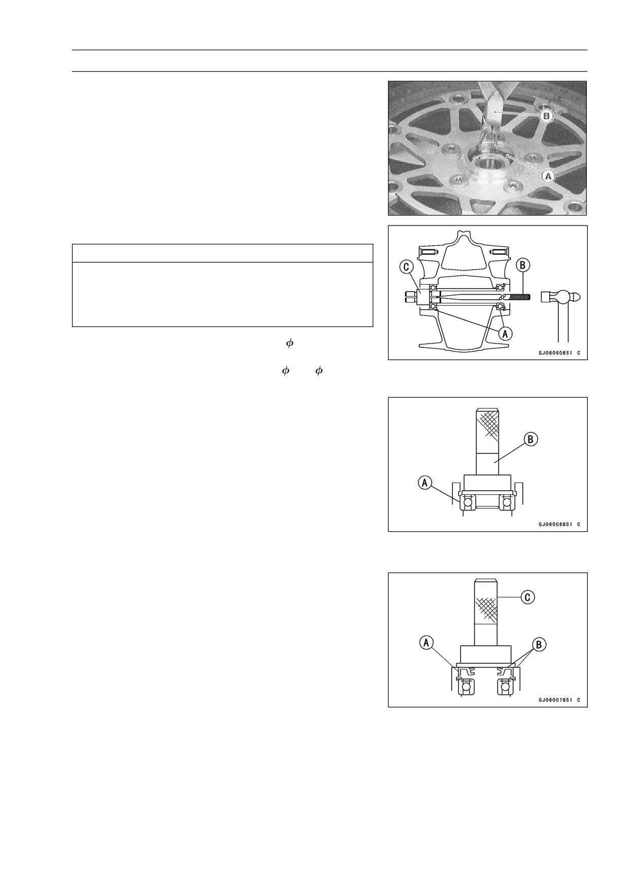
WHEELS/TIRES 9-15
Hub Bearing
Hub Bearing Removal
Remove the wheel, and take out the following.
•
Collars
Coupling (out of rear hub)
Grease Seals
Circlips [A]
Special Tool - Inside Circlip Pliers: 57001-143 [B]
Use the bearing remover to remove the hub bearing [A].
•
CAUTION
Do not lay the wheel on the ground with the disc
facing down. This can damage or warp the disc.
Place blocks under the wheel so that the disc does
not touch the ground.
Special Tools - Bearing Remover Shaft,
13:
57001-1377
[B]
Bearing Remover Head,
25 ×
28: 57001
-1346 [C]
Hub Bearing Installation
Before installing the wheel bearings, blow any dirt or for-
•
eign particles out of the hub with compressed air to pre-
vent contamination of the bearings.
Replace the bearings with new ones.
•
NOTE
○Install the bearings so that the marked side faces out.
Install the bearings by using the bearing driver set which
•
does not contact the bearing inner race.
Press in each right the bearing [A] until they are bottomed.
•
Special Tool - Bearing Driver Set: 57001-1129 [B]
Replace the circlips with new ones.
•
Special Tool - Inside Circlip Pliers: 57001-143
Replace the grease seals with new ones.
•
Press in the grease seals [A] so that the seal surface is
•
flush [B] with the end of the hole.
○Apply high temperature grease to the grease seal lips.
Special Tool - Bearing Driver Set: 57001-1129 [C]
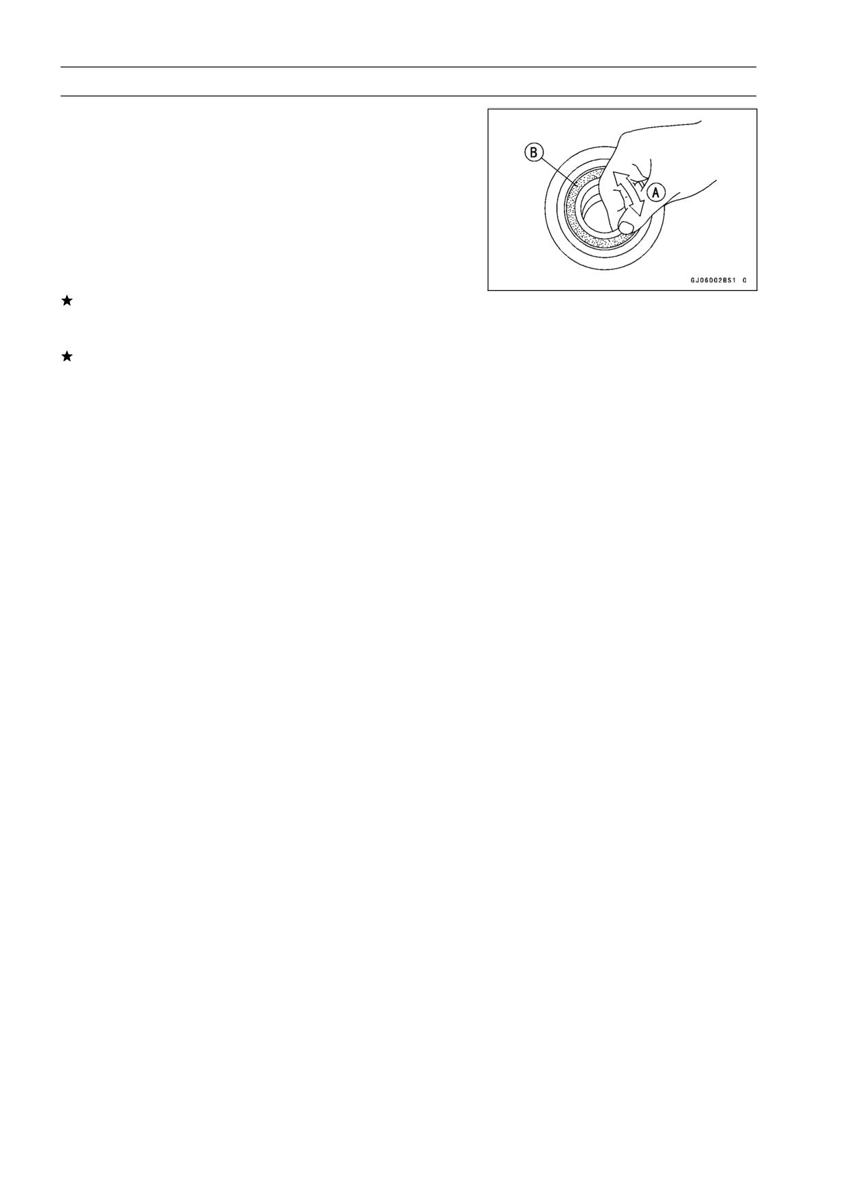
9-16 WHEELS/TIRES
Hub Bearing
Hub Bearing Inspection
Since the hub bearings are made to extremely close tol-
erances, the clearance can not normally be measured.
NOTE
○Do not remove any bearings for inspection. If any bear-
ings are removed, they will need to be replaced with
new ones.
Turn each bearing in the hub back and forth [A] while
•
checking for plays, roughness, or binding.
If bearing play, roughness, or binding is found, replace
the bearing.
Examine the bearing seal [B] for tears or leakage.
•
If the seal is torn or is leaking, replace the bearing.
Hub Bearing Lubrication
NOTE
○Since the hub bearings are packed with grease and
sealed, lubrication is not required.
FINAL DRIVE 10-1
Final Drive
Table of Contents
Exploded View
10-2
Specifications
10-3
Drive Chain
10-4
Drive Chain Slack Inspection
10-4
Drive Chain Slack Adjustment
10-4
Wheel Alignment Inspection/Adjustment
10-4
Drive Chain Wear Inspection
10-5
Drive Chain Lubrication
10-5
Drive Chain Removal
10-6
Drive Chain Installation
10-6
Drive Chain Replacement (ZX600-J4 ∼ (US), ZX600J6F ∼ (CA))
10-7
Sprocket, Coupling
10-10
Engine Sprocket Removal
10-10
Engine Sprocket Installation
10-10
Rear Sprocket Removal
10-11
10
Rear Sprocket Installation
10-11
Coupling Installation
10-11
Coupling Bearing Removal
10-11
Coupling Bearing Installation
10-12
Coupling Bearing Inspection
10-12
Coupling Bearing Lubrication
10-12
Coupling Damper Inspection
10-12
Sprocket Wear Inspection
10-13
Rear Sprocket Warp Inspection
10-13
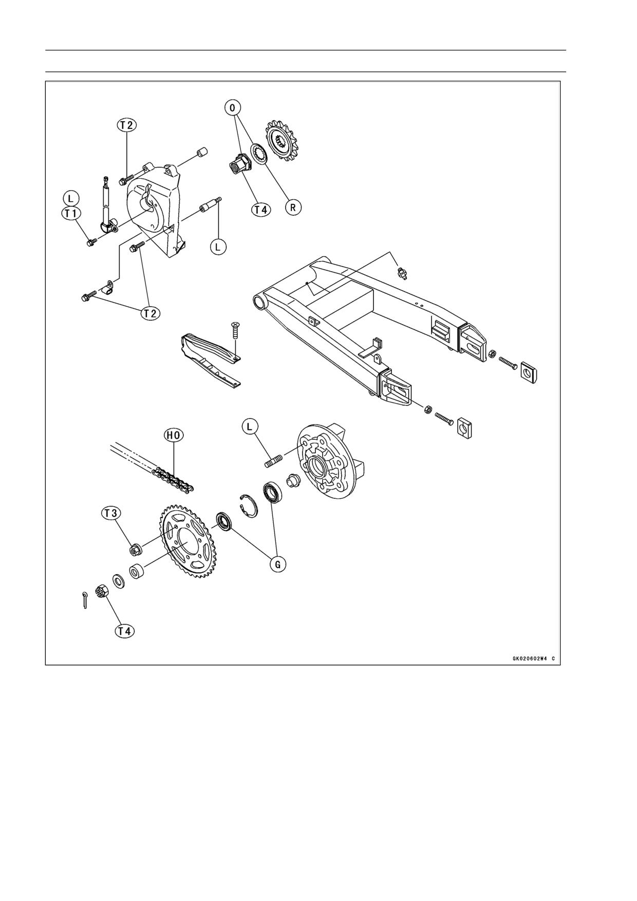
10-2 FINAL DRIVE
Exploded View
T1: 6.9 N·m (0.7 kgf·m, 61 in·lb)
T2: 12 N·m (1.2 kgf·m, 104 in·lb)
T3: 59 N·m (6.0 kgf·m, 43 ft·lb)
T4: 127 N·m (13.0 kgf·m, 94 ft·lb)
G: Apply grease.
HO: Apply heavy oil.
L: Apply a non-permanent locking agent.
O: Apply oil.
R: Replacement Parts
FINAL DRIVE 10-3
Specifications
Item
Standard
Service Limit
Drive Chain
Chain Slack
30 ∼ 35 mm (1.18 ∼ 1.38 in.)
20-Link Length
317.5 ∼ 318.2 mm (12.50 ∼ 12.53 in.)
323 mm (12.72 in.)
Standard Chain:
Make
ENUMA
- - -
Type
EK525MVXL, Endless (ZX600-J1 ∼ J3)
- - -
EK525UVXL2, Endless (ZX600-J4 ∼) (US)
EK525UVXL2, Endless (ZX600-J6F ∼) (CA)
Link
108 links
- - -
Sprockets
Rear Sprocket Warp
0.4 mm (0.016 in.) or less
0.5 mm (0.020 in.)
US: United States Model
CA: Canada Model
Special Tools - Inside Circlip Pliers: 57001-143
Bearing Driver Set: 57001-1129
Jack: 57001-1238
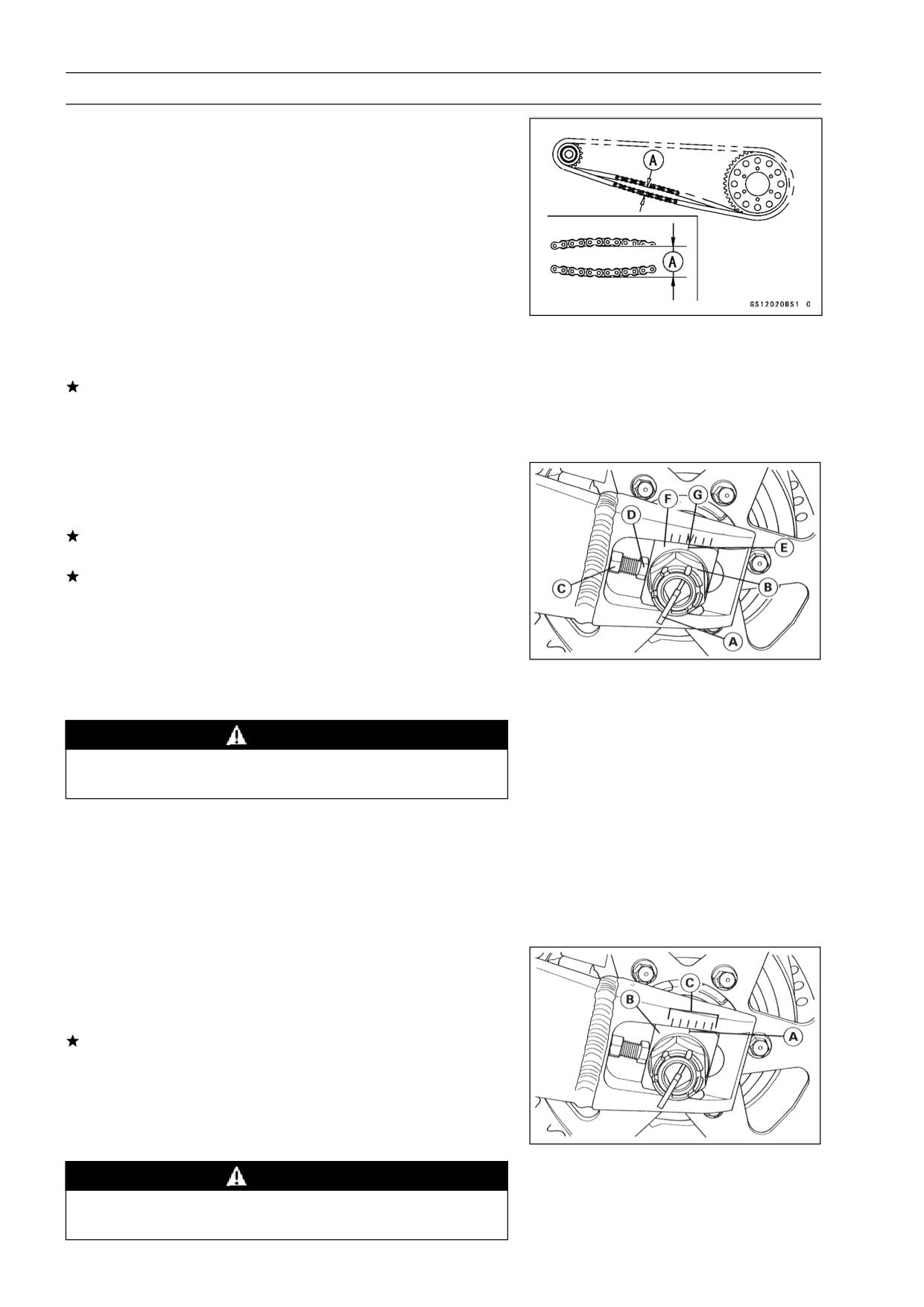
10-4 FINAL DRIVE
Drive Chain
Drive Chain Slack Inspection
NOTE
○Check the slack with the motorcycle setting on its side
stand.
○Clean the chain if it is dirty, and lubricate it if it appears
dry.
Check the wheel alignment (see Wheel Alignment Inspec-
•
tion).
Rotate the rear wheel to find the position where the chain
•
is tightest.
Measure the vertical movement (chain slack) [A] midway
•
between the sprockets.
If the chain slack exceeds the standard, adjust it.
Chain Slack
Standard:
30 ∼ 35 mm (1.18 ∼ 1.38 in.)
Drive Chain Slack Adjustment
Remove the cotter pin [A], and loosen the axle nut [B].
•
Loosen the both chain adjuster locknuts [C].
•
If the chain is too loose, turn out the left and right chain
adjuster [D] evenly.
If the chain is too tight, turn in the left and right chain
adjusters evenly, and kick the wheel forward.
Turn both chain adjusters evenly until the drive chain has
•
the correct amount of slack. To keep the chain and wheel
properly aligned, the notch [E] on the left wheel alignment
indicator [F] should align with the same swingarm mark or
position [G] that the right indicator notch aligns with.
WARNING
Misalignment of the wheel will result in abnormal
wear and may result in an unsafe riding condition.
Tighten both chain adjuster locknuts securely.
•
Tighten the axle nut.
•
Torque - Rear Axle Nut: 108 N·m (11 kgf·m, 80 ft·lb)
Turn the wheel, measure the chain slack again at the tight-
•
est position, and readjust if necessary.
Insert a new cotter pin and spread its ends.
•
Wheel Alignment Inspection/Adjustment
Check that the notch [A] on the left alignment indicator [B]
•
aligns with the same swingarm mark or position [C] that
the right alignment indicator notch aligns with.
If they do not, adjust the chain slack and align the wheel
alignment (see Slack Adjustment ).
NOTE
○Wheel alignment can be also checked using the
straightedge or string method.
WARNING
Misalignment of the wheel will result in abnormal
wear, and may result in an unsafe riding condition.
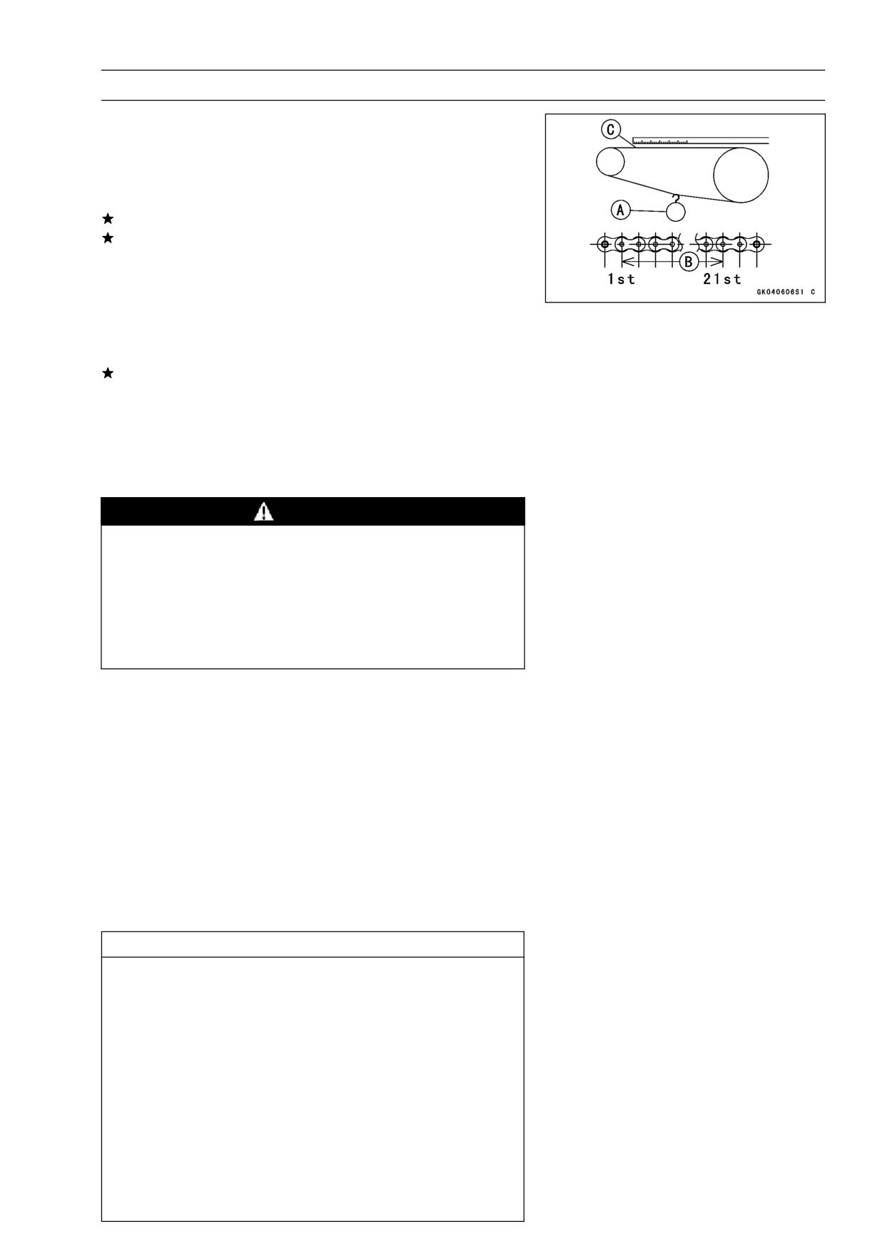
FINAL DRIVE 10-5
Drive Chain
Drive Chain Wear Inspection
Remove:
•
Chain Cover
Rotate the rear wheel to inspect the drive chain for dam-
•
aged rollers, and loose pins and links.
If there is any irregularity, replace the drive chain.
Lubricate the drive chain if it appears dry.
Stretch the chain taut by hanging a 98 N (10 kg, 20 lb)
•
weight [A] on the chain.
Measure the length of 20 links [B] on the straight part [C] of
•
the chain from the pin center of the 1st pin to the pin center
of the 21st pin. Since the chain may wear unevenly, take
measurements at several places.
If any measurements exceed the service limit, replace the
chain. Also, replace the front and rear sprockets when the
drive chain is replaced.
Drive Chain 20-link Length
Standard:
317.5 ∼ 318.2 mm (12.50 ∼ 12.53 in.)
Service Limit:
323 mm (12.72 in.)
WARNING
If the drive chain wear exceeds the service limit, re-
place the chain or an unsafe riding condition may
result. A chain that breaks or jumps off the sprock-
ets could snag on the engine sprocket or lock the
rear wheel, severely damaging the motorcycle and
causing it to go out of control.
For safety, use only the standard chain.
Standard Chain
Make: ENUMA
Type: EX525MVXL, Endless (ZX600-J1 ∼ J3)
EX525UVXL2 (ZX600-J4 ∼ (US), ZX600J6F ∼ (CA))
Link:
108 Links
Drive Chain Lubrication
If a special lubricant is not available, a heavy oil such as
•
SAE 90 is preferred to a lighter oil because it will stay on
the chain longer and provide better lubrication.
If the chain appears especially dirty, clean it before lubri-
•
cation.
CAUTION
The O-rings between the side plates seal in the lu-
bricant between the pin and the bushing. To avoid
damaging the O-rings and resultant loss of lubri-
cant, observe the following rules.
Use only kerosene or diesel oil for cleaning an O
-ring drive chain.
Any other cleaning solution such as gasoline
or trichloroethylene will cause deterioration and
swelling of the O-ring.
Immediately blow the chain dry with compressed air
after cleaning.
Complete cleaning and drying the chain within 10
minutes.
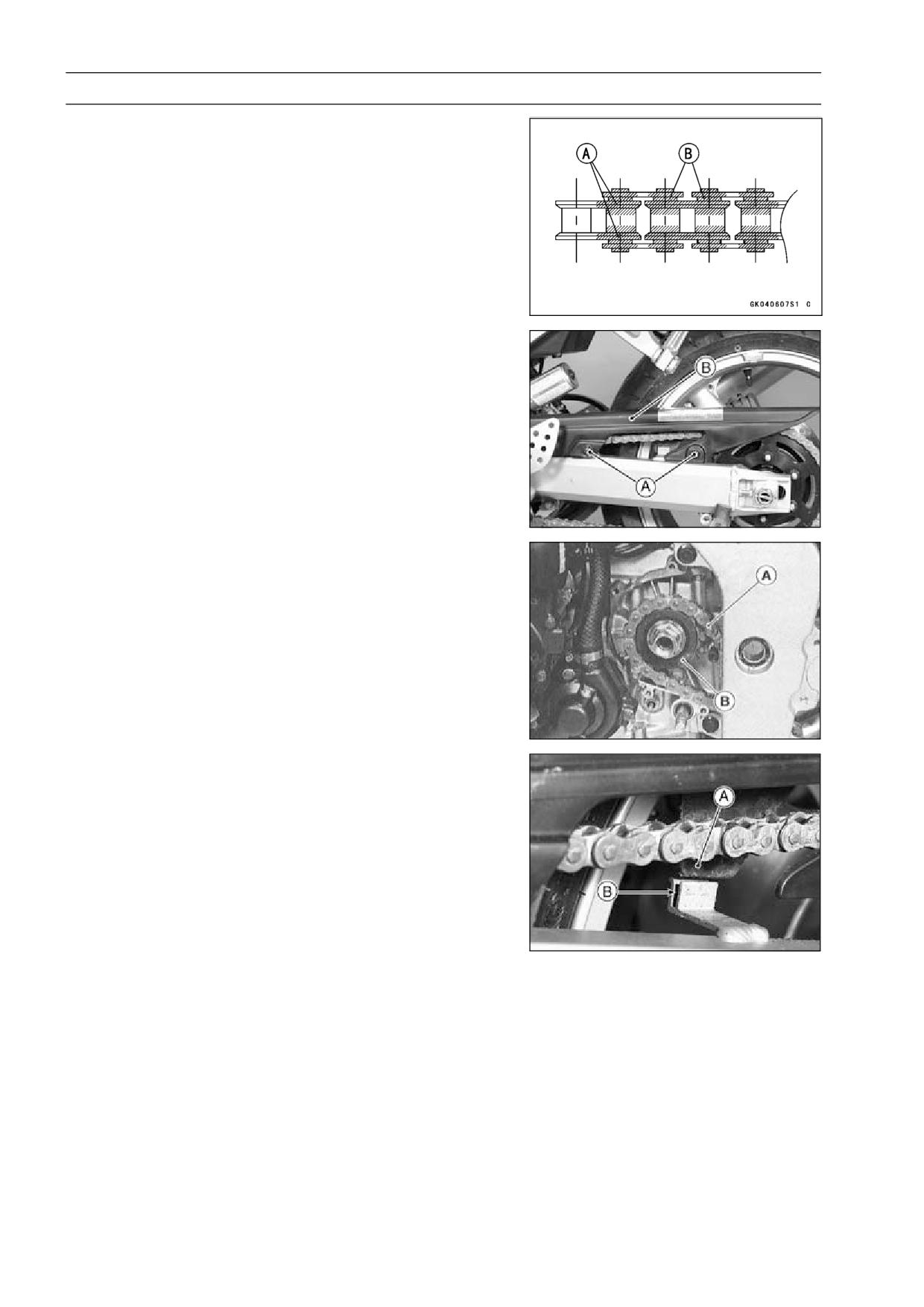
10-6 FINAL DRIVE
Drive Chain
Apply oil to the sides of the rollers so that oil will penetrate
•
to the rollers and bushings. Apply the oil to the O-rings so
that the O-rings will be coated with oil.
Wipe off any excess oil.
•
Oil Applied Areas [A]
O-ring [B]
Drive Chain Removal
Remove:
•
Chain Cover Screws [A]
Chain Cover [B]
Rear Wheel (see Wheels/Tires chapter)
Swingarm (see Suspension chapter)
Engine Sprocket Cover (see this chapter)
Disengage the drive chain [A] from the engine sprocket
•
[B], and take it off the chassis.
Drive Chain Installation
Engage the drive chain to the engine sprocket.
•
Install:
•
Swingarm (see Suspension chapter)
Rear Wheel (see Wheels/Tires chapter)
Engine Sprocket Cover
Chain Cover
○Fit the flap [A] into the slot [B] in the swingarm.
Adjust the chain slack after installing the chain (see Slack
•
Adjustment).