Kawasaki Ninja ZX-6R Motorcycle. Service Manual (2001-2002 year) - page 1
1-6 GENERAL INFORMATION
General Specifications
Items
ZX600-J1, J2
ZX600-J3 ∼
Dimensions
Overall Length
2 030 mm (79.9 in.), (PN) 2 060 mm (81.1 in.)
←
Overall Width
730 mm (28.7 in.)
←
Overall Height
1 175 mm (46.3 in.)
←
Wheelbase
1 400 mm (55.1 in.)
←
Road Clearance
145 mm (5.70 in.)
←
Seat Height
820 mm (32.3 in.)
←
Dry Mass
171 kg (377 lb), (CAL) 173 kg (382 lb), (H) 172
←
kg (379 lb)
Curb Mass:
Front
100 kg (221 lb)
←
Rear
96 kg (212 lb), (CAL) 98 kg (216 lb), (H) 97 kg
←
(214 lb)
Fuel Tank Capacity
18 L (4.76 US gal)
←
Performance
Minimum Turning Radius
3.2 m (10.5 ft)
←
Engine
Type
4-stroke, DOHC, 4-cylinder
←
Cooling System
Liquid-cooled
←
Bore And Stroke
66 × 43.8 mm (2.60 × 1.72 in.)
←
Displacement
599 cm³ (36.6 cu in.)
←
Compression Ratio
12.8
←
Maximum Horsepower
81.6 kW (111 PS) @12 500 r/min (rpm),
←
(AU) 80.6 kW (109.6 PS) @12 500 r/min (rpm),
(PR) 78.2 kW (106.3 PS) @12 500 r/min (rpm),
(US) - - -
Maximum Torque
65.6 N·m (6.7 kgf·m, 48 ft·lb) @10 000 r/min
←
(rpm),
(AU) 64.6 N·m (6.6 kgf·m, 48 ft·lb) @10 000
r/min (rpm)
(US) - - -
Carburetion System
Carburetors, Mikuni BDSR 36R × 4
←
Starting System
Electric starter
←
Ignition System
Battery and coil (transistorized)
←
Timing Advance
Electronically advanced(digital igniter)
←
Ignition Timing
From 12.5° BTDC @1 300 r/min (rpm) to 42.5°
←
BTDC @5 000 r/min (rpm)
Spark Plug
NGK CR9E
←
Cylinder Numbering Method
Left to right, 1-2-3-4
←
Firing Order
1-2-4-3
←
Valve Timing:
Inlet:
Open
56° BTDC
←
Close
80° ABDC
←
Duration
316°
←
GENERAL INFORMATION 1-7
General Specifications
Items
ZX600-J1, J2
ZX600-J3 ∼
Exhaust:
Open
61° BBDC
←
Close
33° ATDC
←
Duration
274°
←
Lubrication System
Forced lubrication (wet sump with cooler)
←
Engine Oil:
Grade
API SE, SF or SG
←
API SH, SJ with JASO MA (ZX600J1 ∼ J4, J6F)
←
API SH, SJ or SL with JASO MA (ZX600J7F ∼)
Viscosity
SAE10W-40, 10W-50, 20W-40, or 20W-50
SAE10W-40
Capacity
4.0 L (4.23 US qt)
←
Drive Train
Primary Reduction System:
Type
Gear
←
Reduction Ratio
2.022 (89/44)
←
Clutch Type
Wet multi disc
←
Transmission:
Type
6-speed, constant mesh, return shift
←
Gear Ratios:
1st
2.923 (38/13)
←
2nd
2.062 (33/16)
←
3rd
1.631 (31/19)
←
4th
1.380 (29/21)
←
5th
1.217 (28/23)
←
6th
1.083 (26/24)
←
Final Drive System:
Type
Chain drive
←
Reduction Ratio
2.666 (40/15)
←
Overall Drive Ratio
5.843 @Top gear
←
Frame
Type
Tubular, diamond
←
Caster (Rake Angle)
23.5°
←
Trail
95 mm (3.7 in.)
←
Front Wheel:
Tire Type
Tubeless
←
Tire Size
120/65 ZR17 (56 W)
120/65 ZR17 M/C
(56 W)
Rim Size
J 17M/C × MT3.50
←
Rear Wheel:
Tire Type
Tubeless
←
Tire Size
180/55 ZR17 (73 W)
180/55 ZR17
M/C (73 W)
Rim Size
J 17M/C × MT5.50
←
1-8 GENERAL INFORMATION
General Specifications
Items
ZX600-J1, J2
ZX600-J3 ∼
Front Suspension:
Type
Telescopic fork
←
Wheel Travel
120 mm (4.7 in.)
←
Rear Suspension:
Type
Swingarm (uni-trak)
←
Wheel Travel
135 mm (5.3 in.)
←
Brake Type:
Front
Dual discs
←
Rear
Single disc
←
Electrical Equipment
Battery
12 V 8 Ah
←
Headlight:
Type
Semi-sealed beam
←
Bulb
12 V 60/55 W (quartz-halogen) × 2
←
Tail/Brake Light
12 V 5/21 W × 2
←
Alternator:
Type
Three-phase AC
←
Rated Output
22 A/14 V @5 000 r/min (rpm)
←
Specifications are subject to change without notice, and may not apply to every country.
H: WVTA Approval Model with Honeycomb Catalytic Converter
PN: WVTA Approval Model with Pipe Catalytic Converter (Norway Model)
PR: WVTA Approval Model with Pipe Catalytic Converter (Restricted Power Model)
AU: Australia
CAL: California
US: United States

GENERAL INFORMATION 1-9
Periodic Maintenance Chart (United States and Canada Models)
The scheduled maintenance must be done in accordance with this chart to keep the motorcycle in
good running condition. The initial maintenance is vitally important and must not be neglected.
FREQUENCY
Whichever
* ODOMETER READING
comes
×
1 000 km
Re-
first
(× 1
000
mile)
marks
1
6
12
18
24
30
36
OPERATION
Every
(0.6)
(4)
(7.5)
(12)
(15)
(20)
(24)
Spark plug - clean and gap †
•
•
•
•
•
•
Valve clearance - Inspect †
•
•
•
Air suction valve - Inspect †
•
•
•
•
•
•
Air cleaner element and air vent filter -
clean †#
•
•
•
Throttle grip play - Inspect †
•
•
•
•
Idle speed - Inspect †
•
•
•
•
Carburetor synchronization - Inspect †
•
•
•
Fuel hoses, Connections - Inspect †
•
•
•
•
•
•
Engine oil - change #
6 months
•
•
•
•
•
•
•
Oil filter - replace
•
•
•
•
Evaporative emission control system
(CAL) - Inspect †
•
•
•
•
•
•
•
Drive chain wear - Inspect †#
•
•
•
•
•
•
Brake pad wear - Inspect †#
•
•
•
•
•
•
Brake light switch - Inspect †
•
•
•
•
•
•
•
Steering - Inspect †
•
•
•
•
•
•
•
Rear shock absorber oil leak - Inspect †
•
•
•
Front fork oil leak - Inspect †
•
•
•
Tire wear - Inspect †
•
•
•
•
•
•
Swingarm pivot, Unit-trak linkage -
lubricate
•
•
•
General lubrication - perform
•
•
•
Nut, bolts, and fasteners tightness -
Inspect †
•
•
•
•
Drive chain - lubricate #
600 km
•
•
•
•
•
•
Drive chain slack - Inspect †#
1000 km
•
•
•
•
•
•
•
Brake hoses, connections - Inspect †
•
•
•
•
•
•
Brake fluid level - Inspect †
month
•
•
•
•
•
•
•
Clutch adjust - Inspect †
month
•
•
•
•
•
•
•
Radiator hoses, connections - Inspect †
•
Brake fluid - change
2 years
•
Brake master cylinder cup and dust
4 years
cover - replace
Coolant - change
2 years
•
Caliper fluid seal and dust seal - replace
4 years
Steering stem bearing - lubricate
2 years
•
1-10 GENERAL INFORMATION
Periodic Maintenance Chart (United States and Canada Models)
FREQUENCY
Whichever
* ODOMETER READING
comes
× 1 000 km
Re-
first
(× 1 000 mile)
marks
1
6
12
18
24
30
36
OPERATION
Every
(0.6)
(4)
(7.5)
(12)
(15)
(20)
(24)
Coolant filter - clean
year
#: Service more frequently when operating in severe conditions; dusty, wet, muddy, high speed,
or frequent starting/stopping.
*: For higher odometer readings, repeat at the frequency interval established here.
†: Replace, add, adjust, clean, or torque if necessary.
CAL: California

GENERAL INFORMATION 1-11
Periodic Maintenance Chart (Other than United States and Canada Models)
The scheduled maintenance must be done in accordance with this chart to keep the motorcycle in
good running condition. The initial maintenance is vitally important and must not be neglected.
FREQUENCY
Whichever
* ODOMETER READING
comes
×
1 000 km
Re-
first
(× 1
000
mile)
marks
1
6
12
18
24
30
36
OPERATION
Every
(0.6)
(4)
(7.5)
(12)
(15)
(20)
(24)
Spark plug - clean and gap †
•
•
•
•
•
•
Valve clearance - Inspect †
•
Air suction valve - Inspect †
•
•
•
•
•
•
Air cleaner element and air vent filter -
clean †#
•
•
•
Throttle grip play - Inspect †
•
•
•
•
Idle speed - Inspect †
•
•
•
•
Carburetor synchronization - Inspect †
•
•
•
Fuel hoses, Connections - Inspect †
•
•
•
•
•
•
Engine oil - change #
6 months
•
•
•
•
•
•
•
Oil filter - replace
•
•
•
•
Drive chain wear - Inspect †#
•
•
•
•
•
•
Brake pad wear - Inspect †#
•
•
•
•
•
•
Brake light switch - Inspect †
•
•
•
•
•
•
•
Steering - Inspect †
•
•
•
•
•
•
•
Rear shock absorber oil leak - Inspect †
•
•
•
Front fork oil leak - Inspect †
•
•
•
Tire wear - Inspect †
•
•
•
•
•
•
Swingarm pivot, Unit-trak linkage -
lubricate
•
•
•
General lubrication - perform
•
•
•
Nut, bolts, and fasteners tightness -
Inspect †
•
•
•
•
Drive chain - lubricate #
600 km
•
•
•
•
•
•
Drive chain slack - Inspect †#
1000 km
•
•
•
•
•
•
•
Brake hoses, connections - Inspect †
•
•
•
•
•
•
Brake fluid level - Inspect †
month
•
•
•
•
•
•
•
Clutch adjust - Inspect †
month
•
•
•
•
•
•
•
Radiator hoses, connections - Inspect †
•
Brake fluid - change
2 years
•
Brake master cylinder cup and dust
4 years
cover - replace
Coolant - change
2 years
•
Caliper fluid seal and dust seal - replace
4 years
Steering stem bearing - lubricate
2 years
•
Coolant filter - clean
year
1-12 GENERAL INFORMATION
Periodic Maintenance Chart (Other than United States and Canada Models)
#: Service more frequently when operating in severe conditions; dusty, wet, muddy, high speed,
or frequent starting/stopping.
*: For higher odometer readings, repeat at the frequency interval established here.
†: Replace, add, adjust, clean, or torque if necessary.
GENERAL INFORMATION 1-13
Technical Information-KLEEN (KAWASAKI LOW EXHAUST EMISSION)
The ZX600J have catalytic converters.
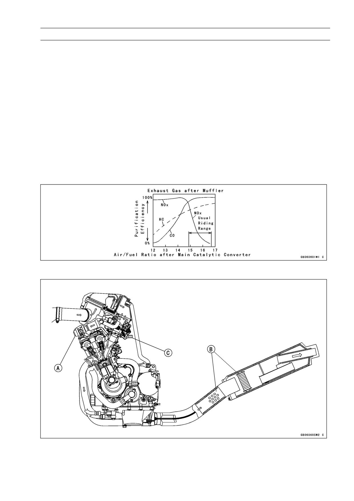
The secondary air injection system [A] helps Kawasaki keep motorcycle exhaust gases below the
established emission regulation limits. This system draws air into the exhaust ports, dilutes and burns
harmful ingredients in the exhaust gas in order to reduce them. This allows the carburetor to be set
at a reasonable setting position without adjusting it much leaner, so engine performance and actual
riding performance are not spoiled.
But, under the trend that the emission regulation becomes more severe, Kawasaki has adopted
two catalytic converters [B] in addition to the secondary air injection system. Moreover, a BDSR 36
-type carburetor has been adopted because of its good balance between cost and performance. As
a result, we can reduce the exhaust gas emission below the current standards without hurting the
output performance and the actual riding feeling at all. The harmful ingredients in the exhaust gas
are reduced considerably under running performance of emission regulation like LA4 or EC mode.
As actual examples, carbon monoxide (CO) is reduced about 70%, hydrocarbons (HC) about 60%,
nitrogen oxides (NOx) about 10%.
Moreover, in order to improve the reliability of the system, we install fuel cut valves [C] as a catalyst
protection system.
Exhaust Gas after Purification
Kawasaki Low Exhaust Emission System
1-14 GENERAL INFORMATION
Technical Information-KLEEN (KAWASAKI LOW EXHAUST EMISSION)
1. Exhaust Purification System
The burned gas, which goes out from the combustion chamber, is injected with secondary air (adding
necessary oxygen), and is cleaned up while passing through the small precatalytic converters in the
joint pipe and the main catalytic converter in the silencer, and then goes out to the atmosphere.
Secondary Air Injection System
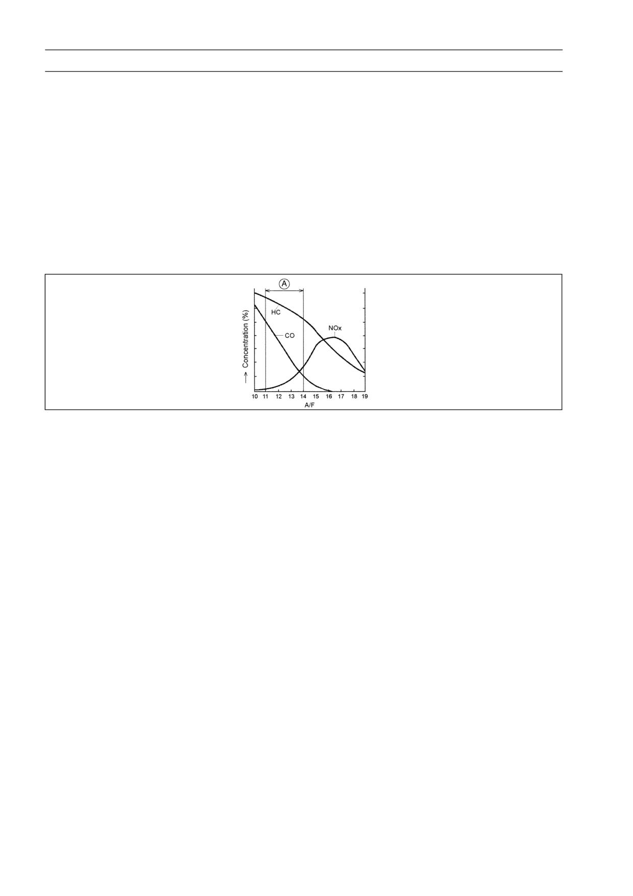
1) In order to oxidize CO, and HC by the catalysts, the proper amount of oxygen is necessary. As
original combustion gas has little remaining oxygen, air is injected in the exhaust ports by the sec-
ondary air injection system in order to supply enough oxygen to the combustion gas to purify CO,
and HC to a certain extent as well as prepare for activation of the catalysts. Since the carburetor
is set at richer level [A], and air/fuel mixture (A/F) is about 11 ∼ 14, NOx is at lower level from the
beginning as shown in the figure. And, A/F becomes lean (about 13.5 ∼ 15) after the combustion
chambers owing to secondary air injection and combustion.
Exhaust Gas before Purification
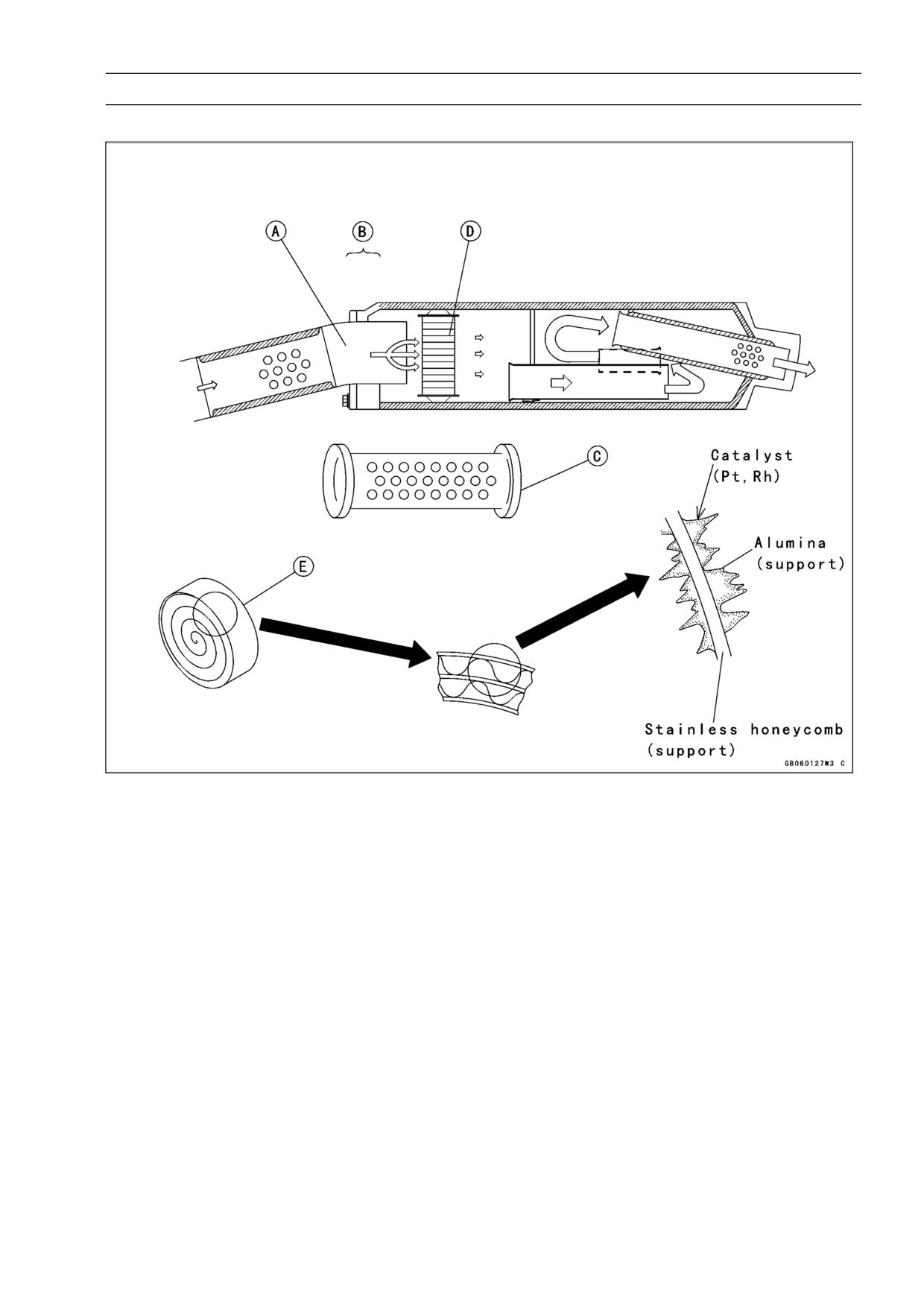
2) Precatalytic Converters [A]
A small-size three-way catalytic converter (precatalytic converter) is installed in the pipe ahead at
the joint [B] of the silencer. A precatalytic converter is made of a punched metal pipe [C] of stain-
less steel, and its surface is covered with alumina upon which platinum and rhodium as catalysts
are applied. Generally, the temperature of the exhaust gas must be higher than the activation tem-
perature, so we set this precatalytic converter at the upper portion of the main catalytic converter
where the temperature of exhaust gas is high. Accordingly, the precatalytic converter will be acti-
vated even under low load conditions. Activation of the precatalytic converter raises the exhaust
gas temperature by the catalyst reaction, which helps the main catalytic converter operate more
efficiently. The precatalytic converter purifies CO, HC, and NOx to a certain extent.
3) Main Catalytic Converters [D]
The converter is a three-way catalytic converter upon which platinum and rhodium are applied,
and has a cylindrical metallic honeycomb structure [E] made by bending a corrugated sheet and
a flat sheet of stainless steel into a spiral of increasing diameter. The main catalytic converter is
installed in the first expansion chamber of the silencer. When the exhaust gas passes through the
upper portion of the secondary air injection system, the precatalytic converter, and the inside of
the honeycomb, the main catalytic converter works efficiently to reduce CO, HC, and NOx. So,
we can keep it within regulation.
The honeycomb structure is convenient for the catalytic converter because it has a large surface
area but small size to react effectively and has low exhaust resistance. In addition, its inherent
strength helps resist vibration, and has simple structure welded directly on the silencer.
GENERAL INFORMATION 1-15
Technical Information-KLEEN (KAWASAKI LOW EXHAUST EMISSION)
Catalytic Converters
2. Catalyst Protection System
When excessive unburned gasoline flows more than the allowable amount into the exhaust gas dur-
ing running, the temperature of the catalysts rises abnormally because the unburned gasoline reacts
with heated catalysts (at the activation temperature or higher). In an excessive case, the problem
such as melting-down occurs. Moreover, there is a possibility that the purification performance be-
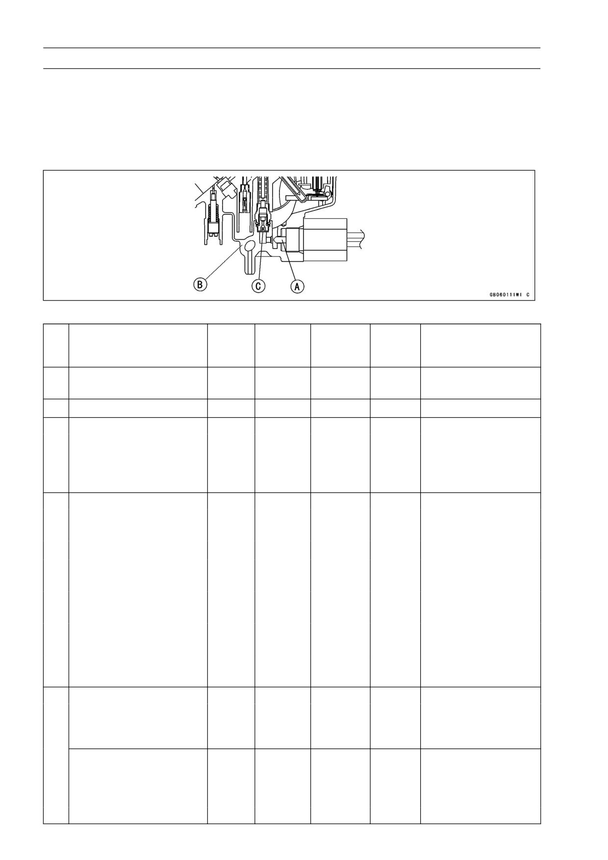
comes poorer when it is cool (below the activation temperature). So, the fuel cut valve [A] as a catalyst
protection system is installed on each carburetor float bowl [B]. It runs by the IC Igniter and opens
and closes the fuel passage toward a main jet [C]. A catalyst protection system works in the following
cases.
1) Prevention of unburned gasoline from flowing when overspeed limiter works.
The limiter has fuel cut-off and ignition cut-off operations.
2) Prevention of unburned gasoline from flowing when the engine stop switch is turned off during
running.
When the engine stop switch is turned off while coasting the motorcycle, fuel is cut off. For ex-
ample, fuel is cut off under the abnormal running condition that you go down the slope with the
engine stop switch OFF.
3) Prevention of unburned gasoline from flowing when misfire occurs by a cutoff of a primary coil in
a stick coil.
Fuel is cut off when an electric current of a primary coil becomes abnormal because of a cutoff of
the primary coil when the engine is running.
4) Prevention of solenoid valve lock
If a driver always runs the engine under the red zone in the tachometer, the IC igniter doesn’t
operate overspeed limiter and the catalyst protection system doesn’t have a chance to work. The
1-16 GENERAL INFORMATION
Technical Information-KLEEN (KAWASAKI LOW EXHAUST EMISSION)
old fuel may gum up the fuel cut valves which remain seated in the float bowls. To cope with, the IC
igniter test-operates the fuel cut valves when starting the engine and prevents lock of the valves.
5) Usage of leaded gasoline is prohibited completely.
Leaded gasoline harms the purification efficiency of the catalysts.
The performance of the catalyst protection system is summed up as follows.
Fuel Cut Valve
Performance of Catalyst Protection System
Engine
Ignition
Protection
Fuel
No
Running Condition
Stop
Remedy (Action)
Switch
System
Cutvalve
Switch
Not necessary
1
Normal
ON
ON
OFF
OPEN
•
(Normal condition)
2
Overspeed performance
ON
ON
ON
Not necessary
CLOSE •
3
Abnormal (misfire)
ON
ON
ON
CLOSE
Defects at the stick coil
Inspect the
•
•
primary-side
connection at the
primary-side of the
stick coil.
4
Abnormal (misfire)
ON
ON
OFF
OPEN
Defects at the stick coil
Inspect the stick coil.
•
•
secondary-side
Battery is dead.
Charge the battery.
•
•
Spark plug fouling
Clean the spark plug
•
•
and adjust the gap.
Defects of the pickup coil
Inspect and replace
•
•
the pickup coil.
Defects of the IC igniter
Inspect and replace
•
•
the IC igniter.
Defects of the carburetor
Inspect and adjust
•
•
the carburetor.
5
Abnormal (no spark)
ON
OFF
ON
CLOSE
Short of the engine stop
Inspect and repair
•
•
switch
the engine stop
switch.
While coasting the
Turn the engine stop
•
•
motorcycle, do not turn
switch ON, and run.
the engine stop switch
OFF.
GENERAL INFORMATION 1-17
Technical Information-KLEEN (KAWASAKI LOW EXHAUST EMISSION)
Engine
Ignition
Protection
Fuel
No
Running Condition
Stop
Remedy (Action)
Switch
System
Cutvalve
Switch
6
Abnormal (no spark)
OFF
ON
OFF
OPEN
Short of the ignition
or
Inspect and replace
•
•
switch
OFF
the ignition switch.
While coasting the
Turn the ignition
•
•
motorcycle, do not turn
switch and the
the ignition switch OFF.
engine stop switch
ON, and run.
3. Maintenance
Special maintenance is not necessary except for the inspection of the air suction valve (which has
been described in this manual).
1) Replacement of Muffler Assy
It is impossible to replace only catalytic converters because they are welded in the muffler. So, in
the following case, the replacement of the muffler assy is also necessary.
In case of using not-appointed fuel (leaded gasoline, etc.):
•
Purification efficiency decreases in a very short period because lead poisons the catalytic con-
verters. Although the appearance of the converter and engine performance are not effected, the
replacement of a muffler assy is necessary to secure the purification efficiency of exhaust gas.
In case catalytic converters melt down by overheating:
•
Especially in the case that a lot of unburned gasoline flows into the catalytic converters under
the extreme running condition far beyond common sense, there is a possibility that the catalysts
overreact and that catalytic converters overheat severely. If they melt down, it causes poor engine
performance, deterioration of emission noise level, and purification efficiency. So, the muffler assy
must be replaced
2) Durability
It has the same durability as a conventional muffler.
3) Disposal to Waste
As any harmful toxic substance is not used especially, it can be disposed as usual industrial wastes.
The body of the muffler is made of aluminum steel. The catalytic converter is also made of stain-
less steel which has alumina on its surface, and the main ingredients of catalysts are platinum and
rhodium.
4. Handling Precautions
Catalyst protection system against mishandling is applied to a vehicle with catalysts. But, we prohibit
depending on the system too much when running.
1) Use only unleaded gasoline:
Usage of leaded gasoline is prohibited completely. Only fuel and additives which are specified in
the Owner’s Manual can be used.
2) Use specified engine oil which is described in the Owner’s Manual:
In case of some ingredients which give bad effects to the catalysts (such as phosphorus “P”, lead
“Pb”, sulfur “S”) are included, the purification efficiency decreases.
3) Coasting (such as cranking while going down a slope) is prohibited with the ignition system OFF:
The engine running without igniting causes a great flow of unburned gasoline and the decreasing
of purification efficiency, and melting down of catalysts at the activation temperature or higher.
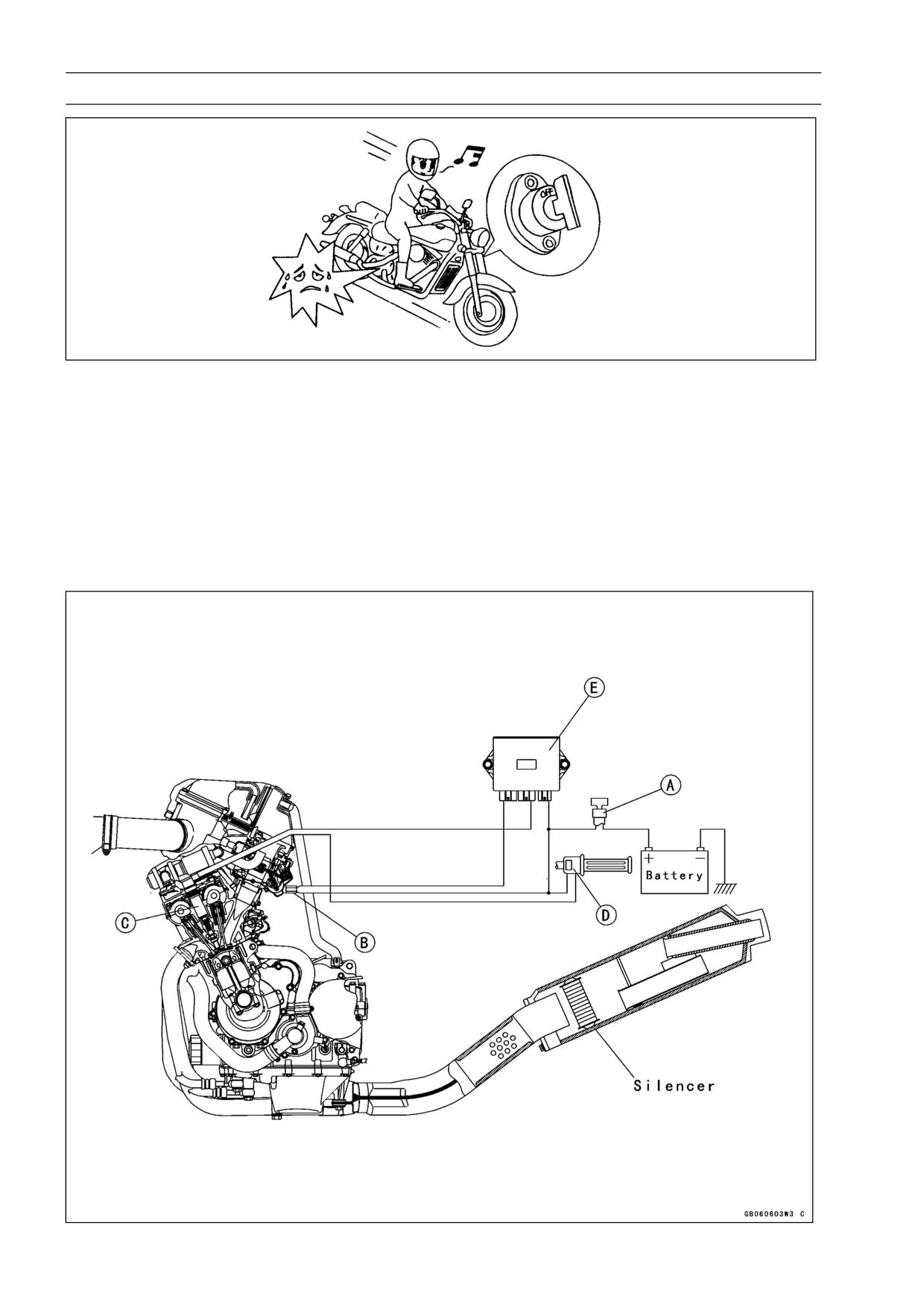
1-18 GENERAL INFORMATION
Technical Information-KLEEN (KAWASAKI LOW EXHAUST EMISSION)
When the ignition switch [A] is turned off, the fuel cut valves [B] do not work. So, avoid coasting
•
with the ignition switch OFF.
Do not run the engine nor coast the motorcycle under the misfire which occurs by defects such as
•
a bad connection with the spark plug at the secondary wiring of the stick coil [C].
Do not coast too much with the engine stop switch [D] OFF. Under the condition that the engine stop
•
switch is turned off during running, the IC igniter [E] closes the fuel cut valves to shut off fuel.
Do not run the engine nor coast the motorcycle too much under the condition that the primary wiring
•
of the stick coil does not connect completely (misfire). Incomplete connection or cut-off of the pri-
mary coil makes the fuel cut valves start to cut fuel. In this case, from the standpoint to protect the
catalysts, the fuel for all cylinders is cut off even if one cylinder has been affected.
Kawasaki Low Exhaust Emission System
GENERAL INFORMATION 1-19
Technical Information-KLEEN (KAWASAKI LOW EXHAUST EMISSION)
Do not run overspeed limiter too much from the standpoint to protect the engine. (Overspeed limiter
•
has a protection system that applies ignition cut method and fuel cut method together. Conventional
system applies fuel-on method.)
Do not run the engine even if only one cylinder has a misfire or has unstable running. In this case,
•
request the nearest service facility to correct it. If you have no choice but running by yourself, keep
engine rpm as low as possible and try to finish running at the shortest period.
When the battery is dead, do not push-start. Connect another full-charged battery with jumper ca-
•
bles, and start the engine.
5. Additional Information
1) Secondary Air Injection System
The mechanism is simple and power loss is minimum because the system uses the vacuum pres-
sure created by exhaust pulses.
The secondary injection air helps the fuel/air mixture burn more completely (Primary air means air
which flows through the inlet pipe). As the exhaust valve opens, and the burned fuel passes the
exhaust valve, a stream of fresh air is introduced through the air suction valve. This fresh air burns
the unburned gas and converts the carbon monoxide (CO) and hydrocarbons (HC) into harmless
carbon dioxide (CO2) and water (H2O).
CO + 1/2 O2 → CO2
HC + O2 → CO2 + H2O
The secondary air injection system consists of a vacuum switch valve, and two air suction valves.
Without using an air pump, the air suction valve can draw fresh air into the exhaust passage near the
exhaust valves by vacuum that exhaust pulses generate.
Air Suction Valves
The air suction valves is a check valve which allows fresh air to flow only from the air cleaner via
air hoses into the exhaust port and prevents return flow. Remove and inspect the air suction valves
periodically (see Engine Top End chapter in this Service Manual). Also, remove and inspect the air
suction valves whenever the idle speed is unstable, engine power is greatly reduced, or there are
abnormal engine noises.
Vacuum Switch Valve
Although the vacuum switch valve usually permits secondary air flow, it closes when a high vacuum
(low pressure) is developed at the inlet pipe during engine braking. This is to shut off secondary air
flow and prevent explosions in the exhaust ports which might be caused by extra unburned fuel in the
exhaust during deceleration. These explosions, or backfiring in the exhaust system could damage
the air suction valves.
Regular inspection of the vacuum switch valve is not needed. If backfiring occurs frequently in the
exhaust system during engine braking or if there are abnormal engine noises, check the vacuum
switch valve as described in the text (see Engine Top End chapter in this Service Manual).
1-20 GENERAL INFORMATION
Technical Information-KLEEN (KAWASAKI LOW EXHAUST EMISSION)
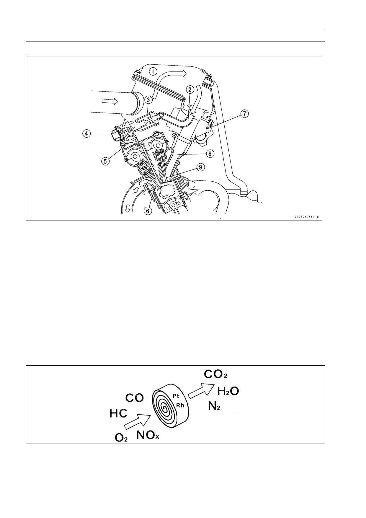
Secondary Air Injection System
1. Air Cleaner Housing
6. Exhaust Valve
2. Air Hose
7. Carburetors
3. Inlet Silencer
8. Inlet Pipe
4. Vacuum Switch Valve
9. Inlet Valve
5. Air Suction Valve
2) Operation of Three-way Catalytic Converter
The three-way catalysts are used for the catalytic converters and the main catalytic converter. These
converters can clean up carbon monoxide (CO), hydrocarbons (HC), and nitrogen oxides (NOx) at
the same time.
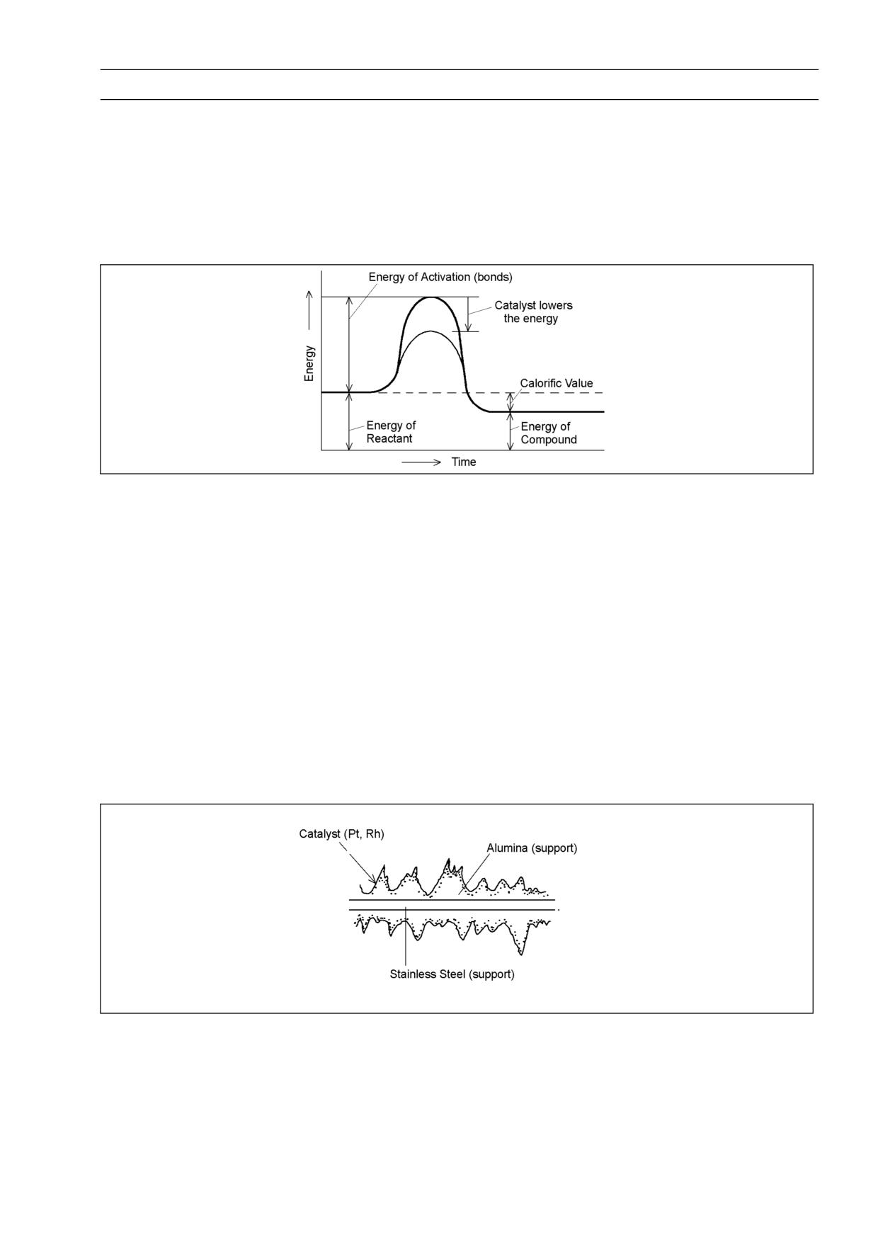
CO and HC are oxidized (O is added) by platinum (Pt) and converted to harmless carbon dioxide
gas (CO2) and water (H2O), and then the exhaust gas is cleaned up:
CO + 1/2 O2 → CO2
HC + O2 → CO2 + H2O
NOx is reduced (O is removed) by rhodium (Rh) and converted to harmless nitrogen (N2) and oxygen
(O2), and the exhaust gas is cleaned up.
NOx → N2 + O2
Main Catalytic Converter
GENERAL INFORMATION 1-21
Technical Information-KLEEN (KAWASAKI LOW EXHAUST EMISSION)
3) Property of Catalyst
Most catalysts are powders of metal or of metallic compounds, and they increase the rate of a
chemical reaction.
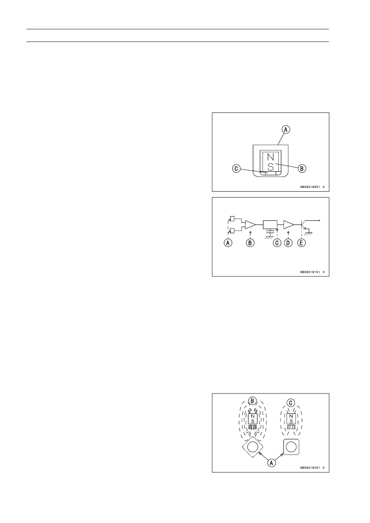
Catalysts are supposed to act in some way to loosen the bonds of the reacting substances. In other
words, they lower the energy of activation, thus allowing the reaction to proceed more rapidly. To
activate catalysts, the temperature of the exhaust gas must be higher than the activation temperature
that is 220° ∼ 230°C for new catalysts, and 270° ∼ 280 °C for used catalysts (after 10 000 ∼ 20 000
km ride).
The catalyst itself undergoes no permanent chemical change, or can be recovered when the chem-
ical reaction is completed. So, the muffler with built-in catalyst has the same durability as the conven-
tional muffler.
The mechanism of catalytic action is supposed to be a surface phenomenon in which reactants
are absorbed onto a small portion of the surface of the catalyst. The catalytic converter is made of
stainless steel and the surface is applied by alumina (aluminum oxide Al2O3). The alumina adheres
to the stainless steel wall and the catalyst adheres to the alumina very well. The alumina surface is
not uniform and there are corners, edges, dislocations, and grain boundaries. Catalyst is applied on
the alumina and this makes the catalyst surface rough. The rougher the surface is, the more actively
the catalyst absorbs the reactants.
If various impurities like lead are absorbed, they block the small portion of the catalyst surface,
preventing absorption of CO, HC, and NOx. This is the reason why leaded fuel poisons the catalyst
without any break on the surface or generation of heat.
Catalysts are generally efficient in small quantities. A catalyst can catalyze the reaction of several
thousand to a million times its weight in reactants. The three-way catalyst is a blend of platinum (Pt)
and rhodium (Rh) which are expensive. But a converter uses only about 0.05 gram of Pt and 0.01
gram of Rh and a main catalytic converter uses only about 0.4 gram of Pt and 0.1 gram of Rh.
1-22 GENERAL INFORMATION
Technical Information - Non-Contact Hall IC-Type Speed Sensor
Details
The electronic combination meter unit, superior to the
conventional type in weight and durability is installed on
the ZX600-J. The hall IC-type speed sensor is installed on
the ZX600-J together with it, which needs no cable and
speedometer gears. Its construction and operation are de-
scribed as follows;
Construction and Operation
The speed sensor [A] consists of a magnet [B] and the
•
Hall IC [C].
The Hall IC consists of Hall element [A], the differential
•
amplifier [B], the high pass filter [C], the comparator [D]
and the output transistor [E].
Hall Element
The semi-conductors (e.g. CaAs, InAs, InSb) are called
as mentioned above. The magnetic induction applied on
the two (2) Hall elements will be converted into the voltage,
and outputted.
Differential Amplifier
This can output the difference between output powers of
the two (2) Hall elements.
High Pass Filter
Sensitivity of the two (2) Hall elements.
Surface magnetic induction of a magnet.
Relative positions of the Hall element, magnet, and de-
tector gear.
↓↓
Able to cancel the DC off-set because of scattering of
differential output.
Comparator & Output Transistor
Able to output the square wave in accordance with the
magnetic induction alternation with the transistor turning on
or off.
The magnetic induction passing through the Hall element
•
will be changed in accordance with the relative position
of the sensor and the rotor nut [A] installed on the engine
sprocket will be rotated.
amount of magnetic induction
when large [B]
when small [C]
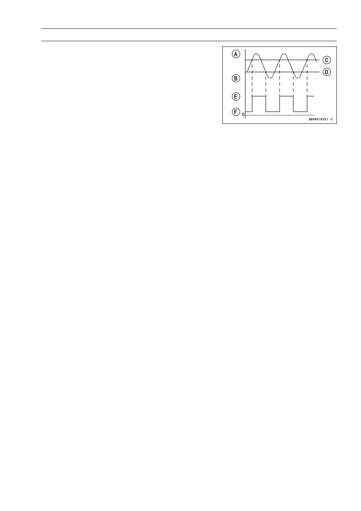
GENERAL INFORMATION 1-23
Technical Information - Non-Contact Hall IC-Type Speed Sensor
In the internal system of the Hall IC, the switch is operated
•
in accordance with the magnetic induction alternator. This
makes the square wave equal to the pulse of the rotor nut
output.
Amount of magnetic induction when large [A]
Amount of magnetic induction when small [B]
Operating point [C]
Returning point [D]
When high voltage [E]
When low voltage [F]
The vehicle speed is indicated in the speedometer, alter-
•
ing the pulse of this square wave.
Speed Sensor Inspection
Refer to the Electrical System chapter 15.
•
1-24 GENERAL INFORMATION
Technical Information - Alternator Made from Rare Magnet
Rare Magnet Material
Sintered metal made from mainly neodium (Nd), ferric
magnet (Fe), and boron (B).
Main Characters
Rare magnet used and assembled in the alternator for the
ZX600-J model has six (6) times higher performance than
that of the traditional use ferrite magnet.
This allows the alternator to reduce its mass and weight
to the large extent. In addition to above mentioned, there’s
no use to worry about the future lackage of rare magnetic
resources such as samarium cobalt.

GENERAL INFORMATION 1-25
Torque and Locking Agent
The following tables list the tightening torque for the major fasteners requiring use of a
non-permanent locking agent or liquid gasket.
Letters used in the “Remarks” column mean:
L: Apply a non-permanent locking agent to the threads.
LG: Apply grease to the threads.
Lh: Left-hand threads.
M: Apply molybdenum disulfide grease.
O: Apply oil to the threads and seating surface.
R: Replacement parts
S: Tighten the fasteners following the specified sequence.
SS: Apply silicone sealant.
St: Stake the fasteners to prevent loosening.
Torque
Fastener
Remarks
N·m
kgf·m
ft·lb
Fuel System
Vacuum Valve Drain Screw
1.0
0.10
9 in·lb
Fuel Tap Bolts
4.9
0.50
43 in·lb
with black
washer
Fuel Tap Bolts
2.5
0.25
22 in·lb
with white
washer
Cooling System
Water Hose Clamp Screws
2.0
0.20
17 in·lb
Coolant By-pass Fitting
9.8
1.0
87 in·lb
L
Coolant Drain Plug (Water Pump)
9.8
1.0
87 in·lb
Coolant Drain Plugs (Cylinder)
9.8
1.0
87 in·lb
Radiator Fan Switch
18
1.8
13
Water Temperature Sensor
7.8
0.80
69 in·lb
SS
Impeller Bolt
9.8
1.0
87 in·lb
Water Pump Cover Bolts
12
1.2
104 in·lb
L
Thermostat Housing Cover Bolts
5.9
0.60
52 in·lb
Water Hose Fitting Bolts
11
1.1
95 in·lb
Engine Top End
Spark Plugs
13
1.3
113 in·lb
Air Suction Valve Cover Bolts
12
1.2
104 in·lb
L
Cylinder Head Cover Bolts
9.8
1.0
87 in·lb
Camshaft Chain Tensioner Mounting Bolts
12
1.2
104 in·lb
Camshaft Cap Bolts
12
1.2
104 in·lb
Camshaft Chain Guide Bolts (Upper)
12
1.2
104 in·lb
Cylinder Head Bolts:
10
49
5.0
36
S, O
(Washer)
6
12
1.2
104 in·lb
S
Cylinder Head Jacket Plugs (Right)
15
1.5
11
L
Cylinder Head Jacket Plugs (Upper, Left)
20
2.0
14.5
L
Engine Side Cover Bolts
12
1.2
104 in·lb
Camshaft Chain Guide Bolt (Crankcase)
25
2.5
18
Carburetor Holder Bolts
12
1.2
104 in·lb

1-26 GENERAL INFORMATION
Torque and Locking Agent
Torque
Fastener
Remarks
N·m
kgf·m
ft·lb
Baffle Plate Bolts
9.8
1.0
87 in·lb
L
Muffler Body and Exhaust Pipe Connecting
45
4.5
33
Nuts
Exhaust Pipe Mounting Bolt
34
3.5
25
Clutch
Clutch Cover Bolts
12
1.2
104 in·lb
L (2, Front)
Clutch Cover Damper Bolts
5.9
0.60
52 in·lb
L
Clutch Spring Bolts
8.8
0.90
78 in·lb
Clutch Hub Nut
137
14
101
R
Engine Lubrication System
Oil Filler Plug
1.5 or
0.15 or
13 in·lb or
Hand-Tight
Hand-Tight
Hand-Tight
Engine Drain Plug
20
2.0
14.5
Oil Filter (Cartridge type)
31
3.2
23
R, O
Oil Cooler Mounting Bolt
78
8.0
58
O
Oil Pan Bolts
9.8
1.0
87 in·lb
Oil Pipe Holder Bolts
12
1.2
104 in·lb
L
Oil Pressure Relief Valve
15
1.5
11
L
Oil Pressure Switch
15
1.5
11
SS
Oil Pressure Switch Terminal Bolt
1.5
0.15
13 in·lb
Impeller Bolt
9.8
1.0
87 in·lb
Oil Passage Plug (Right)
15
1.5
11
Oil Hose Banjo Bolts
25
2.5
18
Engine Removal/Installation
Engine Mounting Bolts and Nuts
44
4.5
33
Engine Mounting Locknuts
49
5.0
36
Engine Mounting Bracket Bolts
25
2.5
18
Crankshaft/Transmission
Breather Plate Bolts
9.8
1.0
87 in·lb
L
Breather Tube Bracket Bolts
12
1.2
104 in·lb
Crankcase Bolts:
8
30
3.0
22
S
7
20
2.0
14.5
S
6, L38 (Front, 6)
18
1.8
13
S
6
12
1.2
104 in·lb
S
Oil Passage Plug (Left)
20
2.0
14.5
L
Oil Passage Plug (Right)
15
1.5
11
Connecting Rod Big End Nuts
in the text
←
←
←
Engine Ground Lead Terminal Bolt
9.8
1.0
87 in·lb
Timing Rotor Bolt
44
4.5
33
Oil Pressure Switch
15
1.5
11
SS
Gear Positioning Lever Bolt
12
1.2
104 in·lb
Shift Shaft Return Spring Pin (Bolt)
28
2.9
21
L

GENERAL INFORMATION 1-27
Torque and Locking Agent
Torque
Fastener
Remarks
N·m
kgf·m
ft·lb
Neutral Switch
15
1.5
11
Shift Drum Bearing Holder Bolt
12
1.2
104 in·lb
L
Shift Drum Bearing Holder Screw
4.9
0.5
43 in·lb
L
Shift Drum Cam Bolt
12
1.2
104 in·lb
L
Oil Pipe Holder Bolts
12
1.2
104 in·lb
L
Crankshaft Sensor Cover Bolts
12
1.2
104 in·lb
L (1)
Oil Nozzles
6.9
0.70
61 in·lb
L
Starter Motor Clutch Bolt
34
3.5
25
L
Wheels/Tires
Front Axle Clamp Bolts
20
2.0
14.5
Front Axle Nut
127
13
94
Rear Axle Nut
127
13
94
Final Drive
Engine Sprocket Nut
127
13
94
O
Engine Sprocket Cover Bolts
12
1.2
104 in·lb
Speed Sensor Mounting Bolt
6.9
0.70
61 in·lb
L
Rear Sprocket Nuts
59
6.0
43
Rear Sprocket Studs
-
-
-
L
Brakes
Bleed Valves
7.8
0.80
69 in·lb
Brake Hose Banjo Bolts
25
2.5
18
Brake Lever Pivot Bolt
1.0
0.10
9 in·lb
Brake Lever Pivot Bolt Locknut
5.9
0.60
52 in·lb
Front Brake Reservoir Cap Stopper Screw
1.5
0.15
13 in·lb
Front Brake Reservoir Bracket Bolt
6.9
0.70
61 in·lb
Front Brake Light Switch Screws
1.0
0.10
9 in·lb
Front Master Cylinder Clamp Bolts
ZX600J1 ∼ J4, J6F
8.8
0.90
78 in·lb
S
ZX600J7F
11
1.1
97 in·lb
S
Front Brake Pad Spring Bolts
2.9
0.30
26 in·lb
Front Caliper Mounting Bolts
34
3.5
25
Front Caliper Assembly Bolts
21
2.1
15
Brake Disc Mounting Bolts
27
2.8
20
L
Rear Caliper Mounting Bolts
25
2.5
18
Rear Master Cylinder Mounting Bolts
25
2.5
18
Rear Master Cylinder Push Rod Locknut
18
1.8
13
Suspension
Front Fork Clamp Bolts (Upper)
20
2.0
14.5
Front Fork Clamp Bolts (Lower)
20
2.0
14.5
Front Fork Top Plugs
23
2.3
16.5
Piston Rod Nut
28
2.9
21
Front Fork Bottom Allen Bolt
39
4.0
29
L
Front Axle Clamp Bolts
20
2.0
14.5

1-28 GENERAL INFORMATION
Torque and Locking Agent
Torque
Fastener
Remarks
N·m
kgf·m
ft·lb
Rear Shock Absorber Nuts (Upper and Lower)
34
3.5
25
Rear Shock Absorber Upper Bracket Nut
59
6.0
43
Swingarm Pivot Shaft Nut
108
11
80
Uni-Trak:
Rocker Arm Nut
34
3.5
25
Tie-Rod Nuts
59
6.0
43
Steering
Steering Stem Head Nut
49
5.0
36
Steering Stem Locknut
4.9
0.5
43 in·lb
Steering Stem Nut
15
1.5
11
Handlebar Bolts
34
3.5
25
L
Handlebar Holder Bolts
25
2.5
18
Handlebar Holder Position Bolts
9.8
1.0
87 in·lb
L
Handlebar Weight Screws
-
-
-
L
Handlebar Switch Housing Screws
3.5
0.35
30 in-lb
Frame
Footpeg Mounting Bolts
34
3.5
25
L
Side Stand Mounting Bolt
44
4.5
33
Grab Rail Bolts
25
2.5
18
Footpeg Bracket Mounting Bolts
25
2.5
18
Side Stand Bracket Bolts
49
5.0
36
Rear Frame Bolts and Nuts
44
4.5
33
Rear Shock Absorber Upper Bracket Nut
59
6.0
43
Electrical System
Spark Plugs
13
1.3
113 in·lb
Alternator Rotor Bolt
120
12
87
Stator Coil Bolts
12
1.2
104 in·lb
L
Alternator Lead Holding Plate Bolts
6.9
0.70
61 in·lb
L
Engine Ground Lead Terminal Bolt
9.8
1.0
87 in·lb
Alternator Cover Bolts
12
1.2
104 in·lb
Crankshaft Sensor Coil Cover Bolts
12
1.2
104 in·lb
L (1)
Crankshaft Sensor Coil Bolts
5.9
0.60
52 in·lb
Timing Rotor Bolt
44
4.5
33
Starter Motor Mounting Bolts
12
1.2
104 in·lb
Handlebar Switch Housing Screws
3.4
0.35
30 in·lb
Radiator Fan Switch
18
1.8
13
Water Temperature Sensor
7.8
0.80
69 in·lb
SS
Oil Pressure Switch
15
1.5
11
SS
Oil Pressure Switch Terminal Bolt
1.5
0.15
13 in·lb
Neutral Switch
15
1.5
11
Starter Lockout Switch Screws
1.0
0.10
9 in·lb
Front Brake Light Switch Screws
1.0
0.10
9 in·lb
GENERAL INFORMATION 1-29
Torque and Locking Agent
Torque
Fastener
Remarks
N·m
kgf·m
ft·lb
Throttle Sensor Mounting Screws
3.4
0.35
30 in·lb
Side Stand Switch Bolt
8.8
0.90
78 in·lb
1-30 GENERAL INFORMATION
Torque and Locking Agent
The table below, relating tightening torque to thread diameter, lists the basic torque for the bolts and
nuts. Use this table for only the bolts and nuts which do not require a specific torque value. All of the
values are for use with dry solvent-cleaned threads.
Basic Torque for General Fasteners
Threads dia.
Torque
(mm)
N·m
kgf·m
ft·lb
5
3.4 ∼ 4.9
0.35 ∼ 0.50
30 ∼ 43 in·lb
6
5.9 ∼ 7.8
0.60 ∼ 0.80
52 ∼ 69 in·lb
8
14 ∼19
1.4 ∼1.9
10.0 ∼ 13.5
10
25 ∼ 34
2.6 ∼ 3.5
19.0 ∼ 25
12
44 ∼ 61
4.5 ∼ 6.2
33 ∼ 45
14
73 ∼ 98
7.4 ∼ 10.0
54 ∼ 72
16
115 ∼ 155
11.5 ∼ 16.0
83 ∼ 115
18
165 ∼ 225
17.0 ∼ 23.0
125 ∼ 165
20
225 ∼ 325
23 ∼ 33
165 ∼ 240
GENERAL INFORMATION 1-31
Special Tools and Sealant
Bearing Puller:
Valve Spring Compressor Assembly:
57001-135
57001-241
Inside Circlip Pliers:
Bearing Puller Adapter:
57001-143
57001-317
Outside Circlip Pliers:
Piston Pin Puller Assembly:
57001-144
57001-910
Oil Pressure Gauge, 10 kgf/cm²:
Fuel Level Gauge:
57001-164
57001-1017
Compression Gauge, 20 kgf/cm²:
Oil Seal & Bearing Remover:
57001-221
57001-1058
1-32 GENERAL INFORMATION
Special Tools and Sealant
Head Pipe Outer Race Press Shaft:
Valve Seat Cutter, 32° -
28:
57001-1075
57001-1119
Steering Stem Nut Wrench:
Valve Seat Cutter, 32° -
30:
57001-1100
57001-1120
Hook Wrench R37.5, R42:
Valve Seat Cutter, 60° -
30:
57001-1101
57001-1123
Valve Seat Cutter, 45° -
27.5:
Valve Seat Cutter Holder Bar:
57001-1114
57001-1128
Valve Seat Cutter, 45° -
32:
Bearing Driver Set:
57001-1115
57001-1129
GENERAL INFORMATION 1-33
Special Tools and Sealant
Valve Spring Compressor Adapter,
20:
Pilot Screw Adjuster, A:
57001-1154
57001-1239
Valve Spring Compressor Adapter,
22:
Clutch Holder:
57001-1202
57001-1243
Fork Outer Tube Weight:
Oil Filter Wrench:
57001-1218
57001-1249
Front Fork Oil Seal Driver:
Spark Plug Wrench, Hex 16:
57001-1219
57001-1262
Jack:
Carburetor Drain Plug Wrench, Hex 3:
57001-1238
57001-1269
1-34 GENERAL INFORMATION
Special Tools and Sealant
Valve Guide Arbor,
4:
Fork Oil Level Gauge:
57001-1273
57001-1290
Valve Guide Reamer,
4:
Flywheel Holder:
57001-1274
57001-1313
Valve Seat Cutter Holder,
4:
Compression Gauge Adapter, M10 × 1.0:
57001-1275
57001-1317
Oil Pressure Gauge Adapter, M18 × 1.5:
Valve Seat Cutter, 60° -
33:
57001-1278
57001-1334
Fork Piston Rod Puller, M12 × 1.25:
Steering Stem Bearing Driver,
42.5:
57001-1289
57001-1344
GENERAL INFORMATION 1-35
Special Tools and Sealant
Steering Stem Bearing Driver Adapter,
41.5:
Fork Cylinder Holder, Hex 24 × □19.5:
57001-1345
57001-1406
Bearing Remover Head,
25 ×
28:
Peak Voltage Adapter:
57001-1346
57001-1415
Bearing Remover Shaft,
13:
Head Pipe Outer Race Driver,
55:
57001-1377
57001-1446
Hand Tester:
Head Pipe Outer Race Driver,
47:
57001-1394
57001-1447
Flywheel Puller Assembly, M38 × 1.5/M35 × 1.5:
Lead Wire - Peak Voltage Adapter:
57001-1405
57001-1449
1-36 GENERAL INFORMATION
Special Tools and Sealant
Engine Mount Nut Wrench:
Flywheel & Pulley Holder:
57001-1450
57001-1605
Needle Adapter Set:
Kawasaki Bond (Silicone Sealant):
57001-1457
56019-120
Throttle Sensor Setting Adapter:
Kawasaki Bond (Liquid Gasket - Gray):
57001-1521
92104-1063
GENERAL INFORMATION 1-37
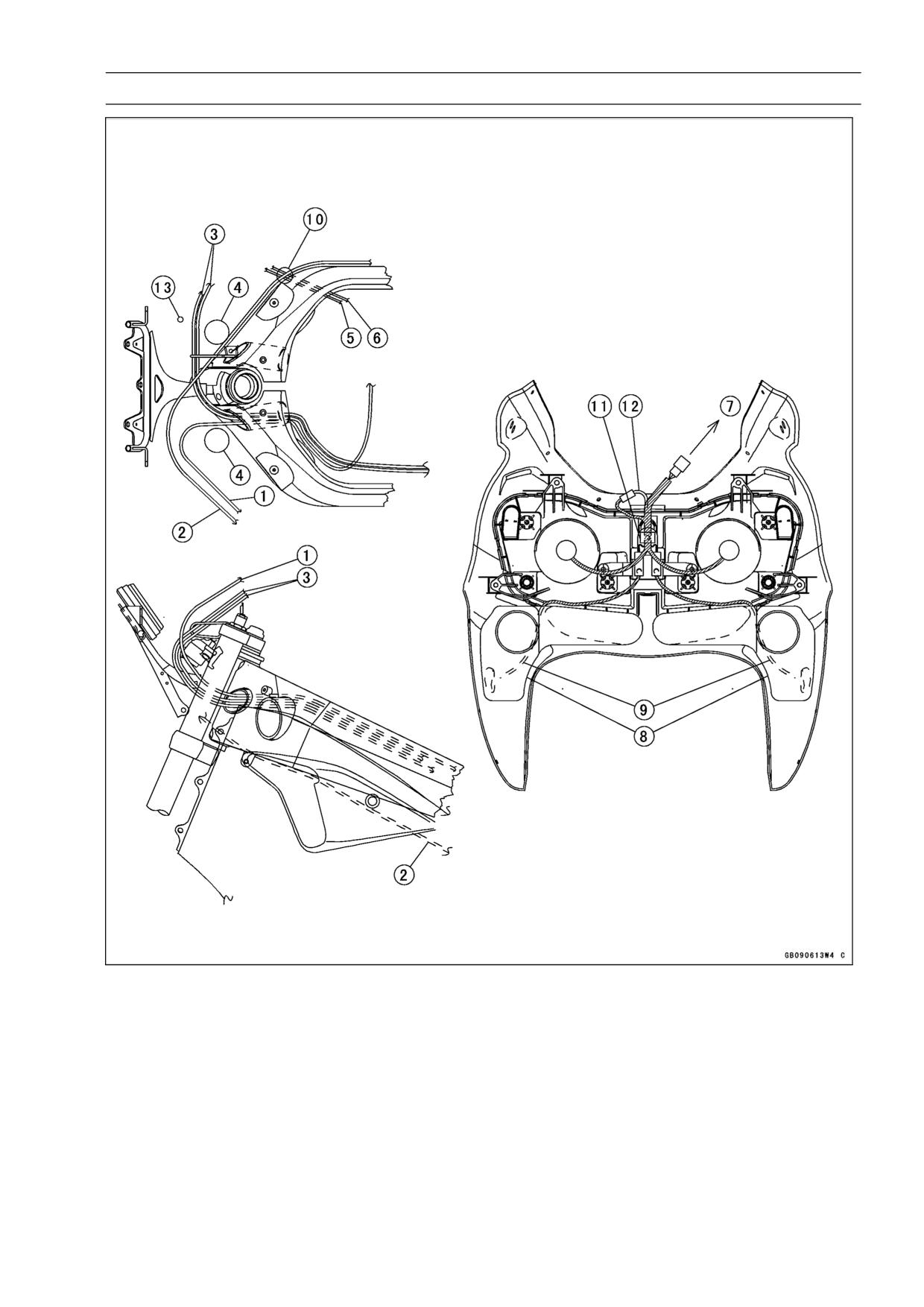
Cable, Wire, and Hose Routing
1. Choke Cable
2. Clutch Cable
3. Throttle Cables
4. Front Fork
5. Coolant Reserve Tank Hose
6. Coolant By-pass Hose
7. To Main Harness
8. Air Intake Duct
9. Turn Signal Light Lead
10. Run the clutch cable over the coolant hoses.
11. Clamp
12. City Light Lead
13. Brake Hose
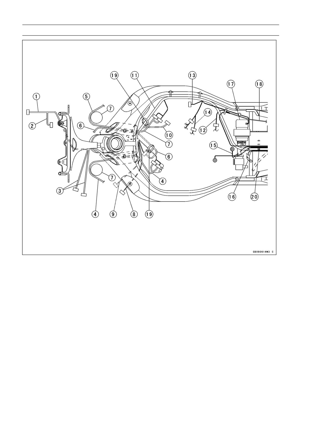
1-38 GENERAL INFORMATION
Cable, Wire, and Hose Routing
1. Meter Lead
2. Headlight/Turn Signal Light Lead
3. Headlight Relay Lead
4. Left Handlebar Switch Lead
5. Right Handlebar Switch Lead
6. Ignition Switch Lead
7. Front Fork
8. Radiator Fan Motor Lead
9. Radiator Fan Switch Lead
10. Stick Coil Lead
11. Main Harness
12. Alternator Lead
13. Throttle Sensor Lead
14. Speed Sensor Lead
15. Engine Ground
16. Frame Ground
17. Fuel Pump
18. Regulator/Rectifier Lead
19. Clamp
20. Band (Main Harness, Battery Cable, Coolant Reserve Overflow Hose)
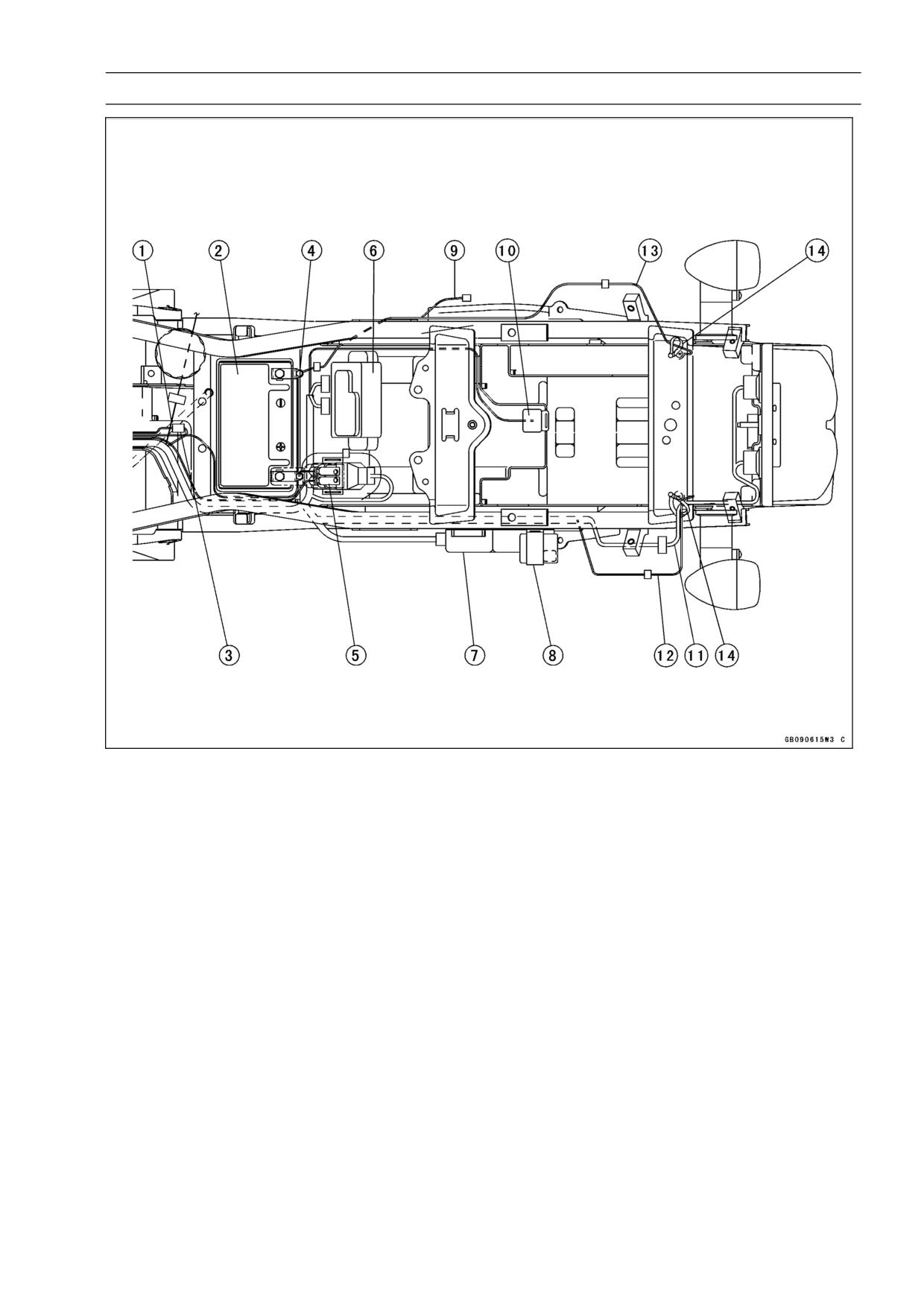
GENERAL INFORMATION 1-39
Cable, Wire, and Hose Routing
1. Rear Brake Switch Lead
2. Battery
3. Alternator Lead Connector
4. Battery (-) Cable
5. Starter Relay
6. Junction Box
7. IC Igniter
8. Fuel Pump Relay
9. Headlight Fuse Lead
10. Turn Signal Relay
11. Tail/Brake Light Lead
12. Left Turn Signal Light Lead
13. Right Turn Signal Light Lead
14. Clamp
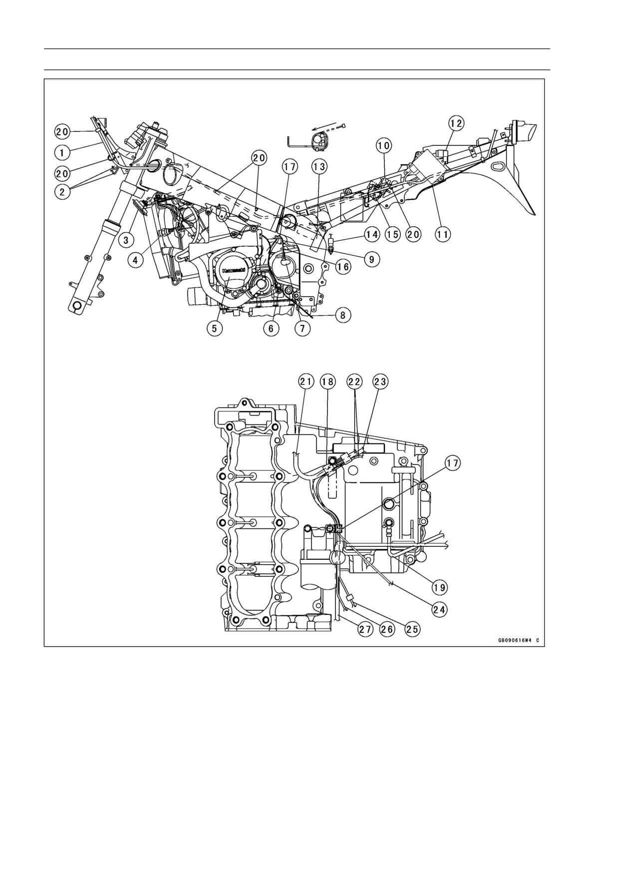
1-40 GENERAL INFORMATION
Cable, Wire, and Hose Routing
1. Headlight/Turn Signal
12. Fuel Pump Relay
19. Engine (Battery) Ground
Light Lead
13. Regulator/Rectifier
Cable
2. Headlight Relay Lead
14. Rear Brake Light Switch
20. Clamp
3. Horn
15. Starter Relay
21. Oil Pressure Switch Lead
4. Radiator Fan Switch
16. Run the speed sensor lead
22. Main Harness
5. Alternator
under the clamp.
23. Regulator/Rectifier Lead
6. Neutral Switch
17. Clamp (Speed Sensor Lead,
24. Speed Sensor Lead
7. Speed Sensor
Side Stand Switch Lead,
25. Side Stand Switch Lead
8. Side Stand Switch Lead
Neutral Switch Lead, Alter-
26. Neutral Switch Lead
9. Speed Sensor Lead
nator Lead)
27. Alternator Lead
10. Junction Box
18. Clamp (Main Harness, Reg-
11. IC Igniter
ulator Lead, Oil Pressure
Switch Lead)
GENERAL INFORMATION 1-41
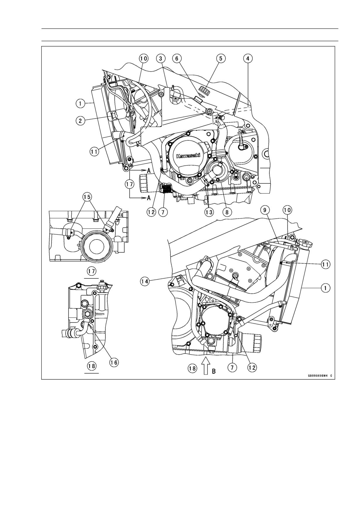
Cable, Wire, and Hose Routing
1. Radiator
11. Face the white mark outward.
2. Radiator Fan Switch
12. Face the white mark forward.
3. Coolant Reserve Tank
13. Align the marks.
4. Reserve Tank Overflow Hose
14. Drain Hose (California model only)
5. Reserve Tank Cap
15. Install the clamps as shown.
6. Rubber Seal
16. The oil hose shall be installed to the lower
7. Oil Cooler
crankcase so that the hose fitting contact
8. Water Pump
to the case.
9. Coolant By-pass Hose
17. View from A-A.
10. Reserve Tank Hose
18. View from B-B.
1-42 GENERAL INFORMATION
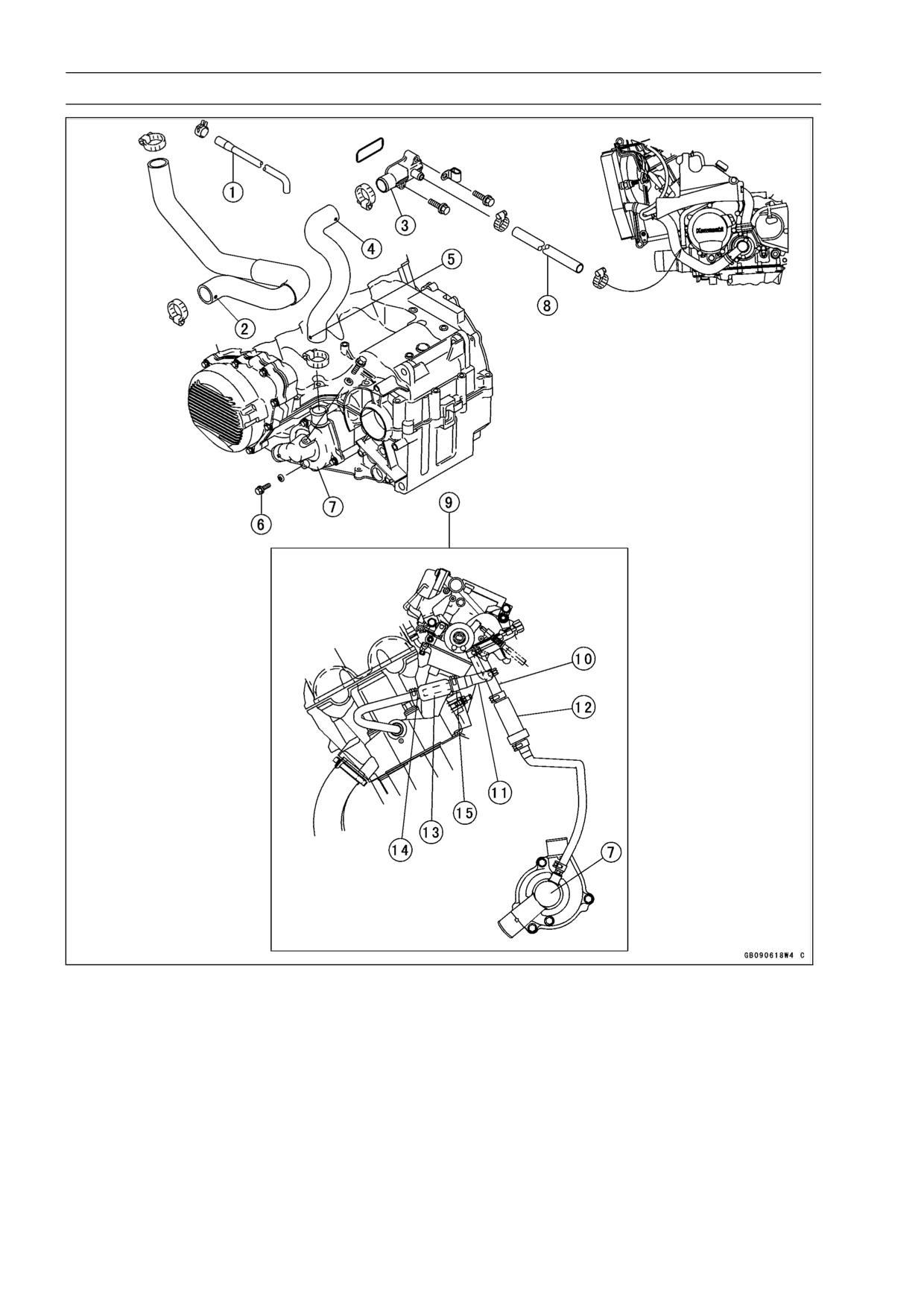
Cable, Wire, and Hose Routing
1. Coolant By-pass Hose
9. Other than US, CA Models
2. Align the mark on the hose with the pro-
10. To #4 Carburetor
jection on the thermostat cover.
11. To #1 Carburetor
3. Cylinder Fitting
12. Coolant Valve
4. Align the mark on the hose with the pro-
13. Coolant Filter
jection on the fitting.
14. Thin Side
5. Align the mark on the hose with the pro-
15. Thick Side
jection on the water pump cover.
US: United States
6. Drain Plug
CA: Canada
7. Water Pump
8. Oil Cooler Hose (Face the white mark for-
wards)
GENERAL INFORMATION 1-43
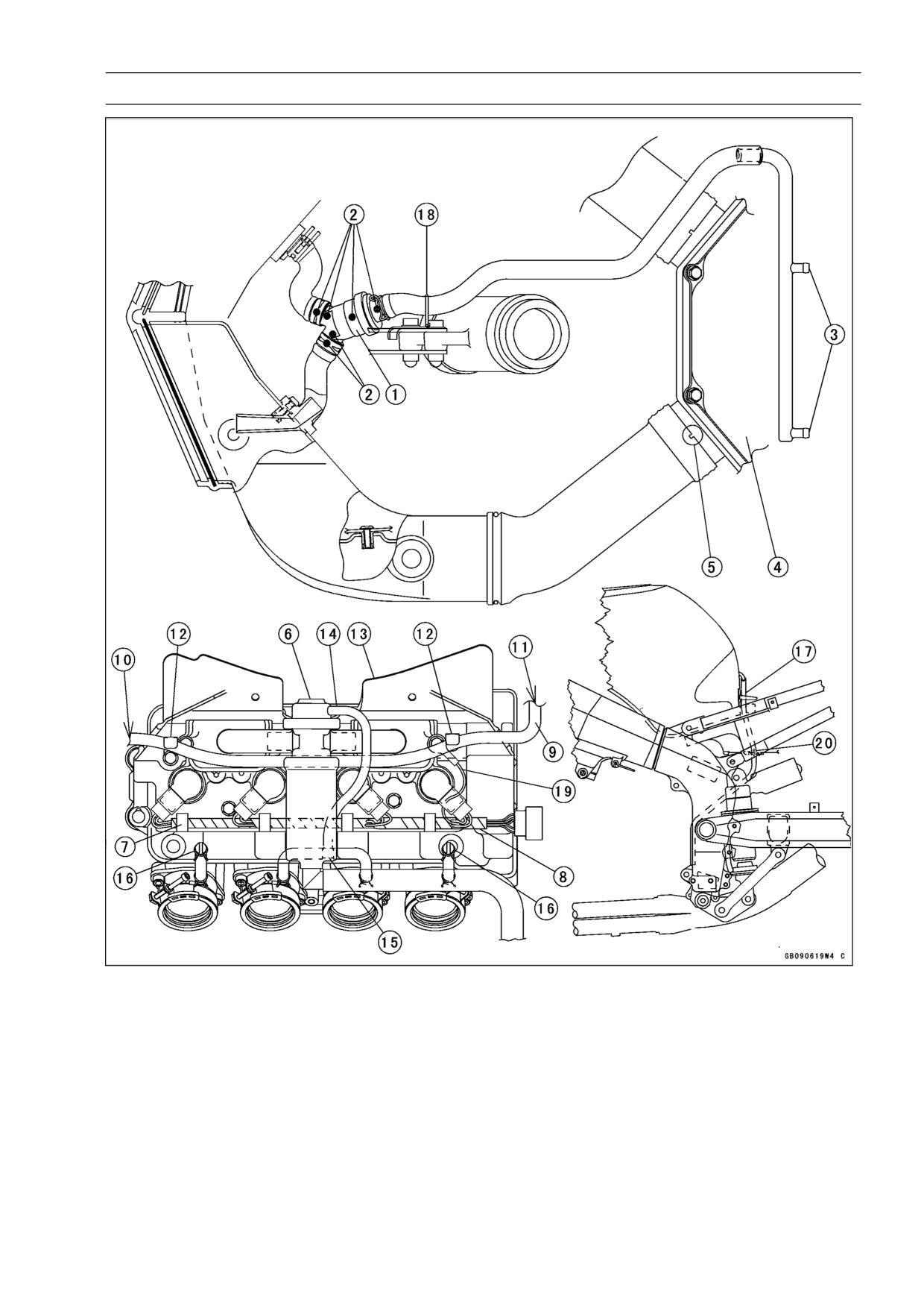
Cable, Wire, and Hose Routing
1. Air Vent Filter
11. To Radiator
2. Align the mark on the hose with the mark
12. Install the clamps with the baffle plate.
on the filter.
13. Baffle Plate
3. To Carburetors
14. Vacuum Hose
4. Air Cleaner Housing
15. Vacuum Hose Fitting
5. Fit the projection of the housing in the re-
16. Plug
cess of the air duct.
17. Fuel Tank Drain Hose
6. Vacuum Switch Valve
18. Clamp (Air Vent Filter Hose)
7. Through the stick coil lead
19. Cylinder Head Cover Ground Lead
8. Stick Coil Lead
20. Run the hose through the hole of the
9. Coolant Reserve Tank Hose
fender.
10. To Coolant Reserve Tank
1-44 GENERAL INFORMATION
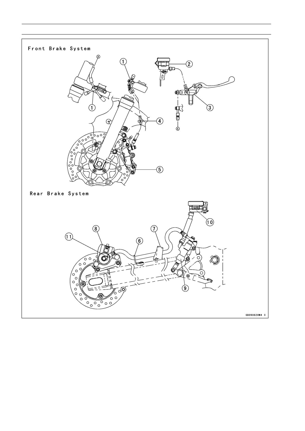
Cable, Wire, and Hose Routing
1. Brake Hose Joint
2. Front Brake Reservoir
3. Front Brake Master Cylinder
4. Clamp (Installed to the front fender)
5. Front Brake Caliper
6. Clamp
7. Clamp
8. Rear Brake Caliper
9. Rear Brake Master Cylinder
10. Rear Brake Reservoir
11. The brake hose shall be installed so that the white mark on it faces to outside.
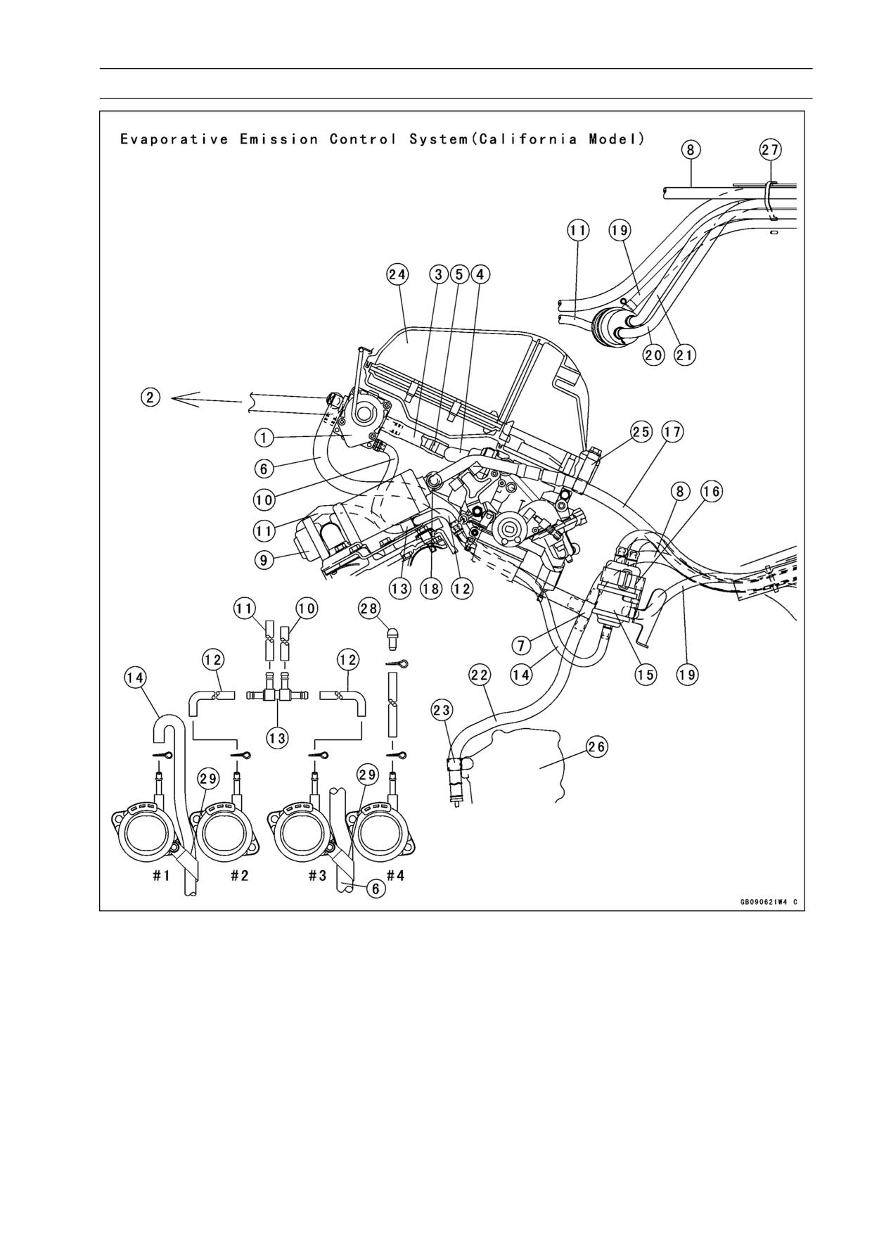
GENERAL INFORMATION 1-45
Cable, Wire, and Hose Routing
1. Vacuum Valve
12. Vacuum Hoses (To #2, #3
20. Breather Hose (To Canis-
2. To Air Vent Filter
Carburetor Holder)
ter, Blue)
3. Carburetor Vent Hose
13. Fitting (4 Way)
21. Breather Hose (To Fuel
4. Carburetor Vent Hoses
14. Vacuum Hose (To #1 Car-
Tank)
5. Fitting (3 Way)
buretor Holder)
22. Drain Hose
6. Carburetor Vent Hose (To
15. Separator
23. Clamp
3 Way Fitting)
16. Band
24. Air Cleaner
7. Fitting
17. Purge Hose (3 Way Fit-
25. Clamp
8. Carburetor Vent Hose (To
ting to Canister, Green)
26. Pickup Coil Cover
Canister, Yellow)
18. Fitting (3 Way)
27. Clamp
9. Vacuum Switch Valve
19. Return Hose (To Fuel
28. Plug
10. Vacuum Hose
Tank)
29. Clamp
11. Vacuum Hose
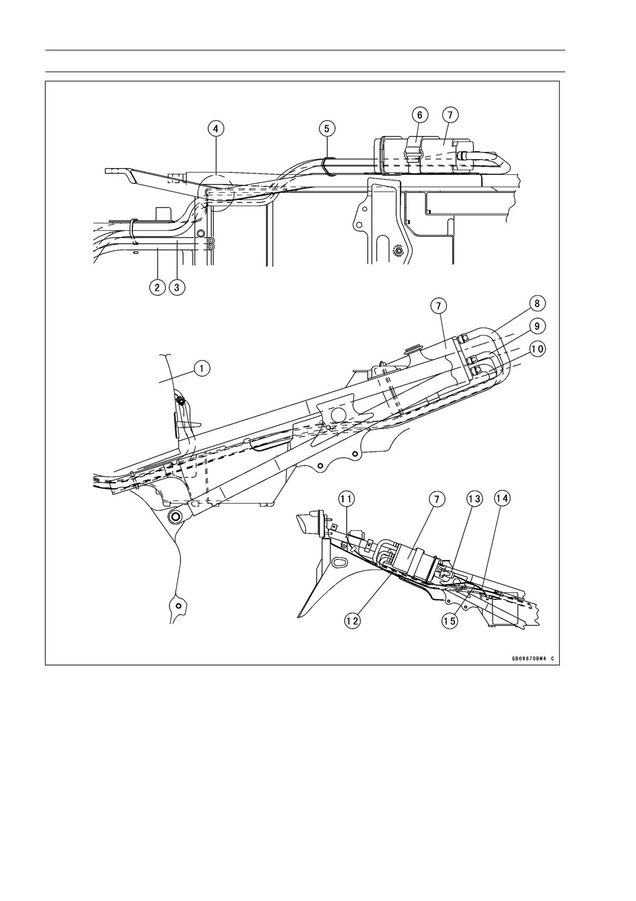
1-46 GENERAL INFORMATION
Cable, Wire, and Hose Routing
1. Fuel Tank
10. Purge Hose (Green)
2. Return Hose (To Fuel Tank, Red)
11. To Right Turn Signal Light
3. Breather Hose (To Fuel Tank, Blue)
12. Canister
4. Through the cut portion of Rear Fender
13. Headlight Fuse
5. Band
14. Run the leads through the rear fender
6. Band
notch.
7. Canister
15. Run the leads over the canister hoses.
8. Carburetor Vent Hose (Yellow)
16. Run the turn signal lead inside of the can-
9. Breather Hose (Blue)
ister hoses.
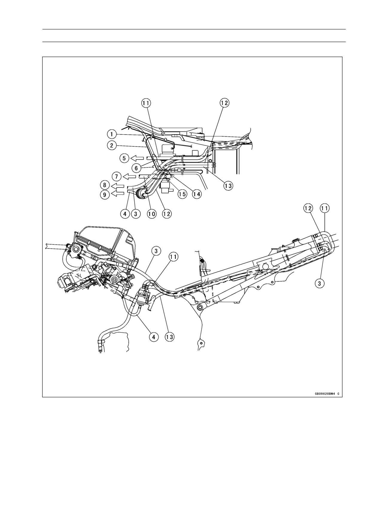
GENERAL INFORMATION 1-47
Cable, Wire and Hose Routing (ZX600-J4)
Evaporative Emission Control System (California Model)
1. Main Harness
10. Fuel Hose
2. Regulator/Rectifier Lead
11. Carburetor Vent Hose (Yellow)
3. Purge Hose (green)
12. Breather Hose (Blue) (To Fuel Tank)
4. Vacuum Hose (To #1 Carburetor Holder)
13. Return Hose (Red) (To Fuel Tank)
5. To Drain Plug
14. Run the red return hose under the regu-
6. Run all the evaporative hoses over the
lator lead, and other hoses over the reg-
main harness.
ulator lead.
7. To Carburetor
15. Run the red return hose under the fuel
8. To Vacuum Switch Valve
hose, and other hoses over the fuel
9. To #1 Carburetor Holder
hoses.
FUEL SYSTEM 2-1
Fuel System
2
Table of Contents
Exploded View
2-2
Coolant Valve Inspection (Other
Specifications
2-5
than United States and Canada
Throttle Grip and Cables
2-6
Models)
2-17
Throttle Grip Play Inspection
2-6
Air Cleaner
2-18
Throttle Cable Installation
2-6
Element Removal
2-18
Throttle Cable Lubrication and
Element Installation
2-18
Inspection
2-6
Element Cleaning and Inspection
2-18
Choke Cable
2-7
Air Cleaner Housing Removal
2-19
Choke Cable Free Play
Air Cleaner Housing Installation...
2-19
Inspection
2-7
Air Vent Filter Cleaning
2-19
Choke Cable Free Play
Fuel Tank
2-20
Adjustment
2-7
Fuel Tank Removal
2-20
Choke Cable Installation
2-7
Fuel Tank Installation
2-20
Choke Cable Lubrication and
Fuel Tank Inspection
2-21
Inspection
2-7
Fuel Tank Cleaning
2-21
Carburetors
2-8
Fuel Tap Removal
2-21
Idle Speed Inspection
2-8
Fuel Tap Installation
2-22
Idle Speed Adjustment
2-8
Fuel Tap Inspection
2-22
Synchronization Inspection
2-8
Fuel Pump, Fuel Filter
2-23
Synchronization Adjustment
2-9
Fuel Pump, Fuel Filter Removal ..
2-23
Service Fuel Level Inspection
2-9
Fuel Pump, Fuel Filter Installation
2-23
Service Fuel Level Adjustment
2-10
Fuel Pump Inspection
2-23
Fuel System Cleanliness
Fuel Filter Inspection
2-23
Inspection
2-11
Evaporative Emission Control System
Carburetor Removal
2-11
(California Model Only)
2-24
Carburetor Installation
2-12
Parts Removal/Installation
2-24
Carburetor Disassembly
2-13
Hose Inspection
2-24
Carburetor Assembly
2-14
Separator Inspection
2-24
Carburetor Separation
2-14
Separator Operation Test
2-25
Carburetor Joining
2-14
Canister Inspection
2-25
Carburetor Cleaning
2-15
Vacuum Valve Inspection
2-26
Carburetor Inspection
2-15
Coolant Filter Cleaning (Other
than United States and Canada
Models)
2-17
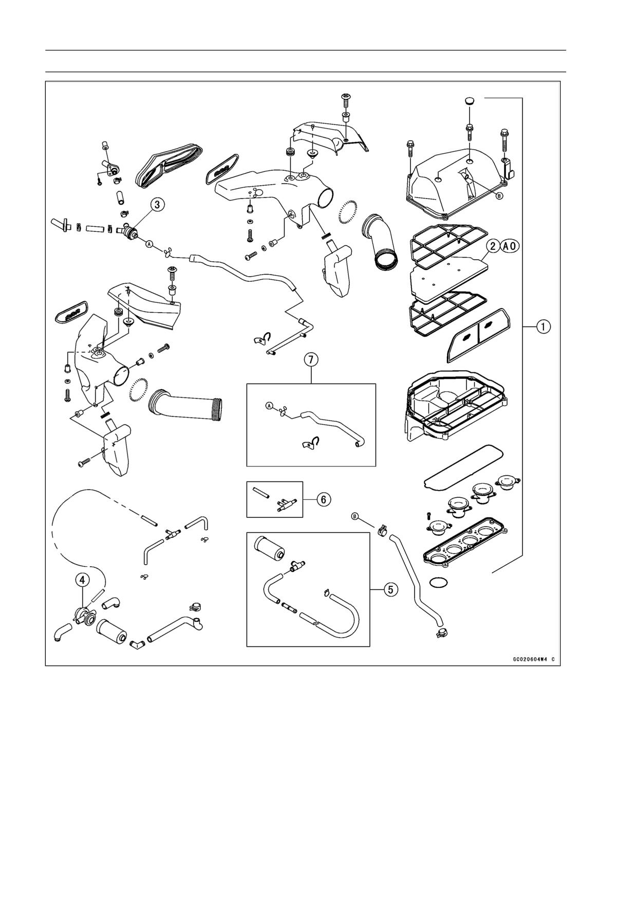
2-2 FUEL SYSTEM
Exploded View
1. Air Cleaner Housing
2. Air Cleaner Element
3. Air Vent Filter
4. Vacuum Switch Valve
5. Silencer Assy (CAL Model)
6. Vacuum Hose Assy (CAL Model)
7. Carburetor Vent Hose (CAL Model)
AO: Apply high quality form air filter oil.
CAL: California
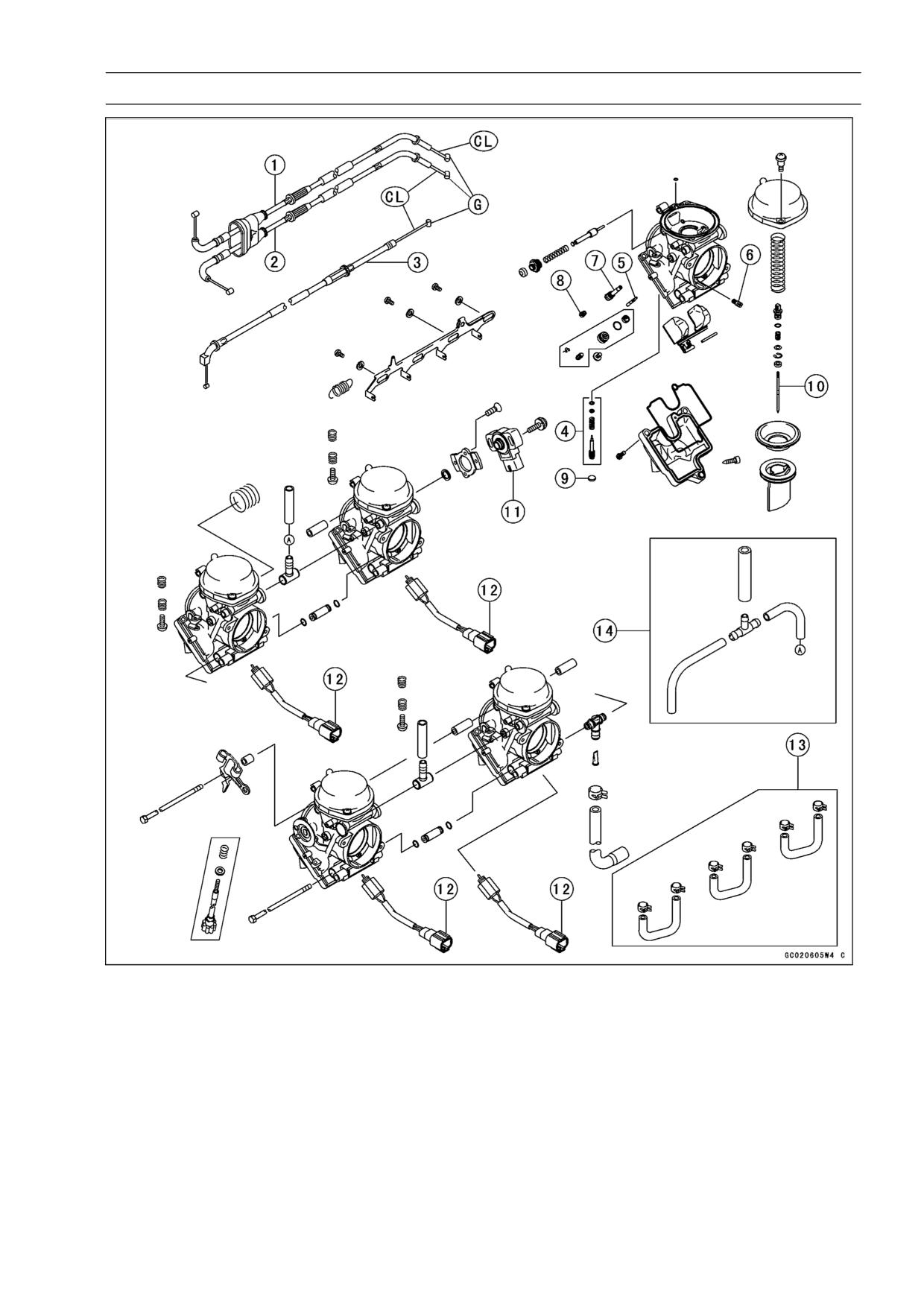
FUEL SYSTEM 2-3
Exploded View
1. Throttle Cable (accelerator)
11. Throttle Sensor
2. Throttle Cable (decelerator)
12. Fuel Cut Valve (CAL, H Models)
3. Choke Cable
13. Cooling Hose Assy (other than US, CA
4. Pilot Screw
Models)
5. Pilot (Slow) Jet
14. Vent Hose Assy (CAL Model)
6. Pilot (Slow) Air Jet
CL: Apply cable lubricant.
7. Needle Jet Holder
G: Apply grease.
8. Main Jet
H: WVTA Approval Model with Honeycomb
9. Plug (US, CA Models)
Catalytic Converter
10. Jet Needle
CA: Canada
CAL: California
US: United States
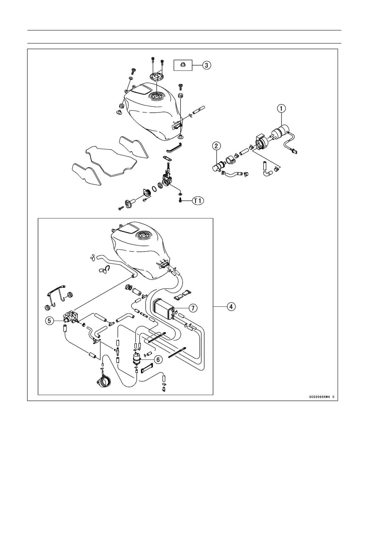
2-4 FUEL SYSTEM
Exploded View
1. Fuel Pump
2. Fuel Filter
3. Seal (CAL Model)
4. Evaporative Emission Control System (CAL Model)
5. Vacuum Valve
6. Separator
7. Canister
T1: 2.5 N·m (0.25 kg·m, 22 in·lb) (with white washer)
4.9 N·m (0.50 kg·m, 43 in·lb) (with black washer)
CAL: California
FUEL SYSTEM 2-5
Specifications
Item
Standard
Throttle Grip And Cables
Throttle Grip Free Play
2 ∼ 3 mm (0.08 ∼ 0.12 in.)
Choke Cable
Free Play
2 ∼ 3 mm (0.08 ∼ 0.12 in.)
Carburetors
Make, Type
MIKUNI, BDSR-36 × 4
Main Jet
#1, 4: #155, #2, 3: #157.5
Main Air Jet
#45
Jet Needle
5E110-54-1,
(Other than US, CA) #1,4; 5E18-3, #2,3: 5E19-3
Pilot Jet (Slow Jet)
#12.5
Pilot Air Jet (Slow Air Jet)
#125
Pilot Screw (Turns Out)
3 turns out
Starter Jet
#35
Idle Speed
1300 ±50 r/min (rpm)
Carburetor Synchronization Vacuum
Less than 2.7 kPa (2 cmHg) difference between any two
carburetors
Service Fuel Level
20.2 ±1 mm (0.80 ±0.04 in.) below the mark on the
carburetor body
Float Height
7 ±2 mm (0.28 ±0.08 in.)
CA: Canada
US: United States
Special Tools - Carburetor Drain Plug Wrench, Hex 3: 57001-1269
Fuel Level Gauge: 57001-1017
Fork Oil Level Gauge: 57001-1290
(as required)
Pilot Screw Adjuster, A: 57001-1239
2-6 FUEL SYSTEM
Throttle Grip and Cables
Throttle Grip Play Inspection
Throttle Grip Free Play Inspection
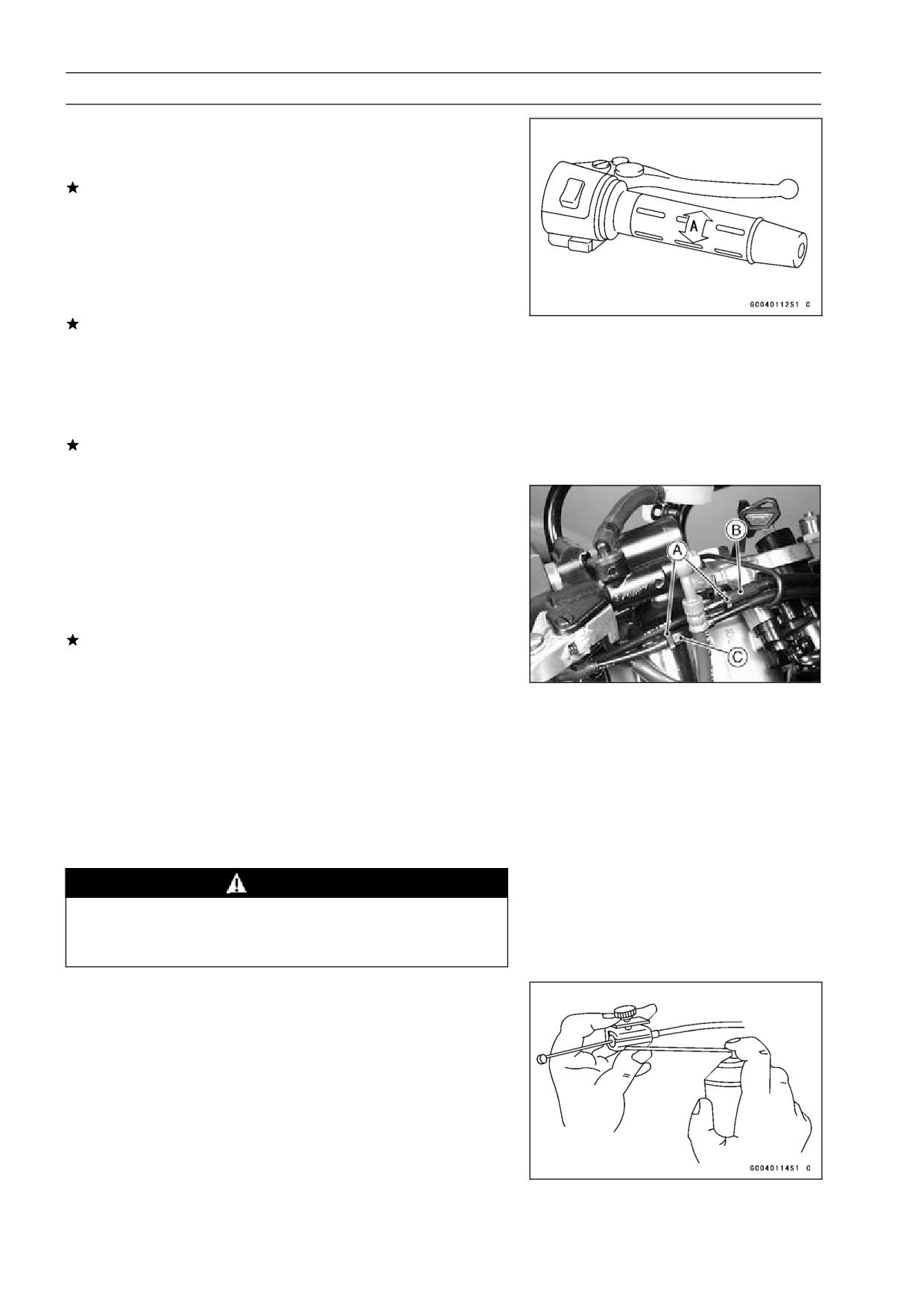
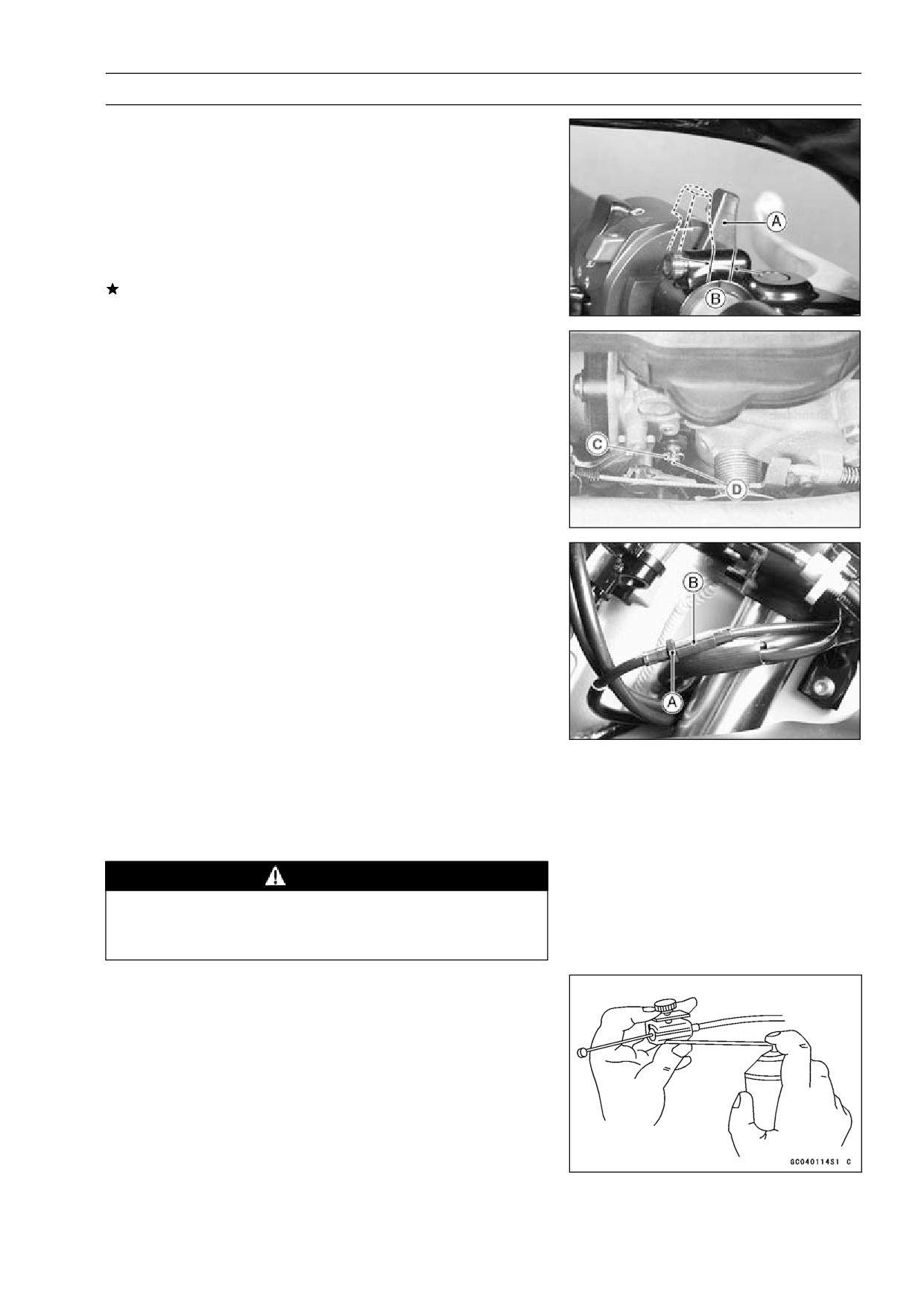
Check the throttle grip free play [A].
•
If the free play is incorrect, adjust the throttle cable.
Throttle Grip Free Play
Standard:
2 ∼ 3 mm (0.08 ∼ 0.12 in.)
Check that the throttle grip moves smoothly from full open
•
to close, and the throttle closes quickly and completely in
all steering positions by the return spring.
If the throttle grip does not return properly, check the throt-
tle cable routing, grip free play, and cable damage. Then
lubricate the throttle cable.
Run the engine at the idle speed, and turn the handlebar
•
all the way to the right and left to ensure that the idle speed
does not change.
If the idle speed increase, check the throttle cable free
play and the cable routing.
Throttle Grip Free Play Adjustment
Loosen the locknuts [A], and screw both throttle cable ad-
•
justers in completely so as to give the throttle grip plenty
of play.
Turn out the decelerator cable adjuster [B] until there is
•
no play when the throttle grip is completely closed.
Tighten the locknut.
•
Turn the accelerator cable adjuster [C] until 2 ∼ 3 mm
(0.08 ∼ 0.12 in.) of throttle grip play is obtained.
Tighten the locknut.
•
Throttle Cable Installation
Install the throttle cables in accordance with Cable, Wire,
•
and Hose Routing section in the General Information
chapter.
Install the lower ends of the throttle cables in the cable
•
bracket on the carburetor after installing the upper ends
of the throttle cables in the grip.
After installation, adjust each cable properly.
•
WARNING
Operation with incorrectly routed or improperly ad-
justed cables could result in an unsafe riding con-
dition.
Throttle Cable Lubrication and Inspection
Whenever the cables are removed, or in accordance with
•
the Periodic Maintenance Chart, lubricate the throttle ca-
bles (see General Lubrication in the Appedix chapter).
○Apply a thin coating of grease to the cable upper ends.
○Use a commercially available pressure cable lubricator to
lubricate the cables.
○With the cable disconnected at both ends, the cable
should move freely in the cable housing.
FUEL SYSTEM 2-7
Choke Cable
Choke Cable Free Play Inspection
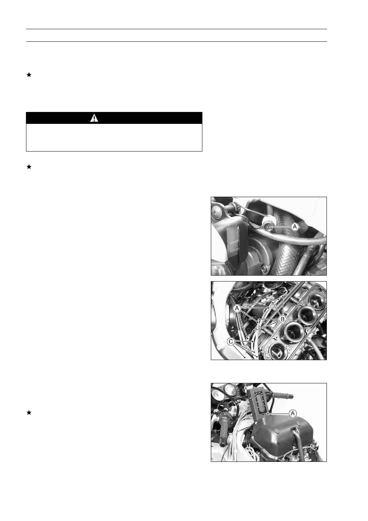
Push the choke lever [A] all the way to the front.
•
Check choke cable free play [B].
•
○Determine the amount of choke cable play at the choke
lever. Pull the choke lever until the starter plunger lever
[C] at the carburetor touches the starter plunger [D]; the
amount of choke lever lower end travel is the amount of
choke cable play.
If the free play is incorrect, adjust the choke cable.
Choke Cable Free Play
Standard:
2 ∼ 3 mm (0.08 ∼ 0.12 in.)
Choke Cable Free Play Adjustment
Loosen the locknut [A], and turn the adjuster [B] until the
•
cable has the proper amount of free play.
Tighten the locknut securely.
•
Choke Cable Installation
Install the choke cable in accordance with the Cable,
•
Wire, and Hose Routing section in the General Informa-
tion chapter.
After installation, adjust the cable properly.
•
WARNING
Operation with an incorrectly routed or improperly
adjusted cable could result in an unsafe riding con-
dition.
Choke Cable Lubrication and Inspection
Whenever the cable is removed, or in accordance with
•
the Periodic Maintenance Chart, lubricate the choke cable
(see General Lubrication in the Appendix chapter).
○Apply a thin coating of grease to the cable upper end.
○Use a commercially available pressure cable lubricator to
lubricate the cable.
○With the cable disconnected at both ends, the cable
should move freely in the cable housing.
2-8 FUEL SYSTEM
Carburetors
Idle Speed Inspection
Start the engine and warm it up thoroughly.
•
With the engine idling, turn the handlebar to both sides.
•
If handlebar movement changes the idle speed, the
throttle cables may be improperly adjusted or incorrectly
routed, or damaged. Be sure to correct any of these
conditions before riding (see Cable, Wire, and Hose
Routing section in the General Information chapter).
WARNING
Operation with improperly adjusted, incorrectly
routed, or damaged cables could result in an un-
safe riding condition.
Check idle speed.
•
If the idle speed is out of the specified range, adjust it.
Idle Speed
Standard:
1 300 ±50 r/min (rpm)
Idle Speed Adjustment
Start the engine and warm it up thoroughly.
•
Turn the adjusting screw [A] until the idle speed is correct.
•
○Open and close the throttle a few times to make sure that
the idle speed is within the specified range. Readjust if
necessary.
Synchronization Inspection
Start the engine and warm it up thoroughly.
•
Check the idle speed (see Idle Speed Inspection).
•
Remove the fuel tank and air cleaner housing (see Fuel
•
Tank Removal and Air Cleaner Housing Removal).
Supply fuel to the carburetors with an auxiliary fuel tank.
•
For the models other than the California model, remove
•
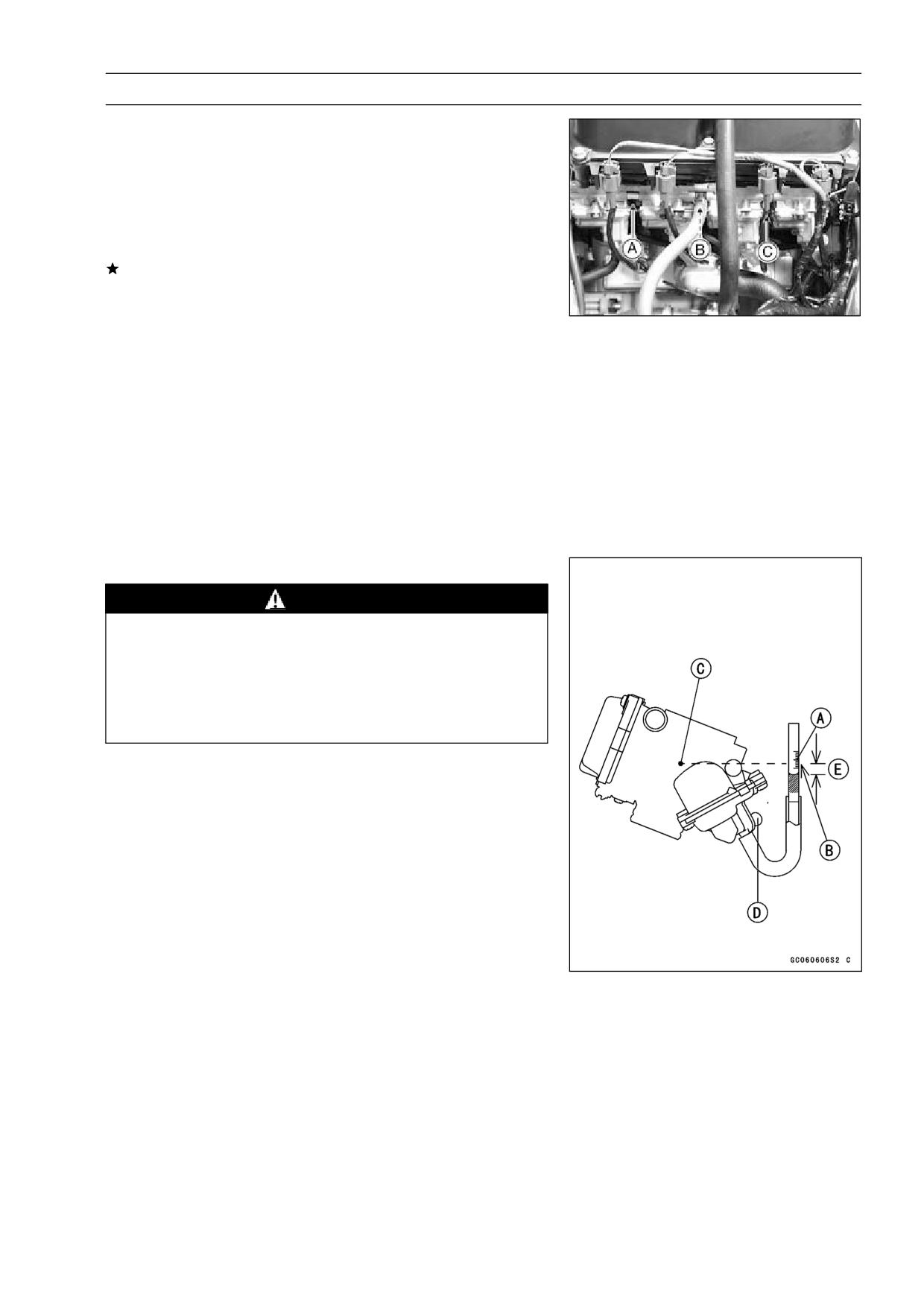
the #1, 4 carburetor vacuum hose plugs and #2, 3 carbu-
retor vacuum hose fitting.
Connect the suitable pipe joints [A] to the carburetor vac-
•
uum hoses [B] and vacuum gauge hoses [C].
Install the air cleaner housing.
•
Connect the vacuum gauge hoses to a vacuum gauge [A].
•
Start the engine and let it idle to measure the carburetor
•
intake vacuum.
If the vacuum is incorrect, adjust the synchronization.
Carburetor Synchronization Vacuum
Standard: Less than 2.7 kPa (2 cmHg) difference
between any two carburetors.
FUEL SYSTEM 2-9
Carburetors
Synchronization Adjustment
Turn the adjusting screw to synchronize the carburetors.
•
○Apply grease to the tip of the adjusting screw threads.
○First synchronize the left two and then the right two car-
buretors by means of the left and right adjusting screws
[A, C]. Then synchronize the left two carburetors and the
right two carburetors using the center adjusting screw [B].
If the carburetor synchronization cannot be obtained by
using the adjusting screws, check for dirt or blockage, and
then check the pilot screw settings.
Special Tool - Pilot Screw Adjuster, A: 57001-1239
Check the carburetor synchronization again.
•
NOTE
○Do not turn the pilot screws carelessly during carburetor
synchronization. You may cause poor running at low
engine speed.
For the other than the California model, remove the car-
•
buretor vacuum hose plugs and carburetor vacuum hose
fitting.
Check the idle speed.
•
Service Fuel Level Inspection
WARNING
Gasoline is extremely flammable and can be ex-
plosive under certain conditions. Turn the ignition
switch OFF. Do not smoke. Make sure the area is
well-ventilated and free from any source of flame
or sparks; this includes any appliance with a pilot
light.
Situate the motorcycle so that it is perpendicular to the
•
ground.
Remove the fuel tank (see Fuel Tank Removal).
•
Prepare an auxiliary fuel tank and connect the fuel hose
•
to the carburetors.
Prepare a fuel hose.
•
Connect the fuel level gauge [A] to the carburetor float
•
bowl with the fuel hose.
Special Tool - Fuel Level Gauge: 57001-1017
Hold the gauge vertically against the side of the carburetor
•
body so that the "middle" line [B] is several millimeters
higher than the mark [C] on the carburetor body.
Feed fuel to the carburetor, then turn the carburetor drain
•
plug [D] out a few turns.
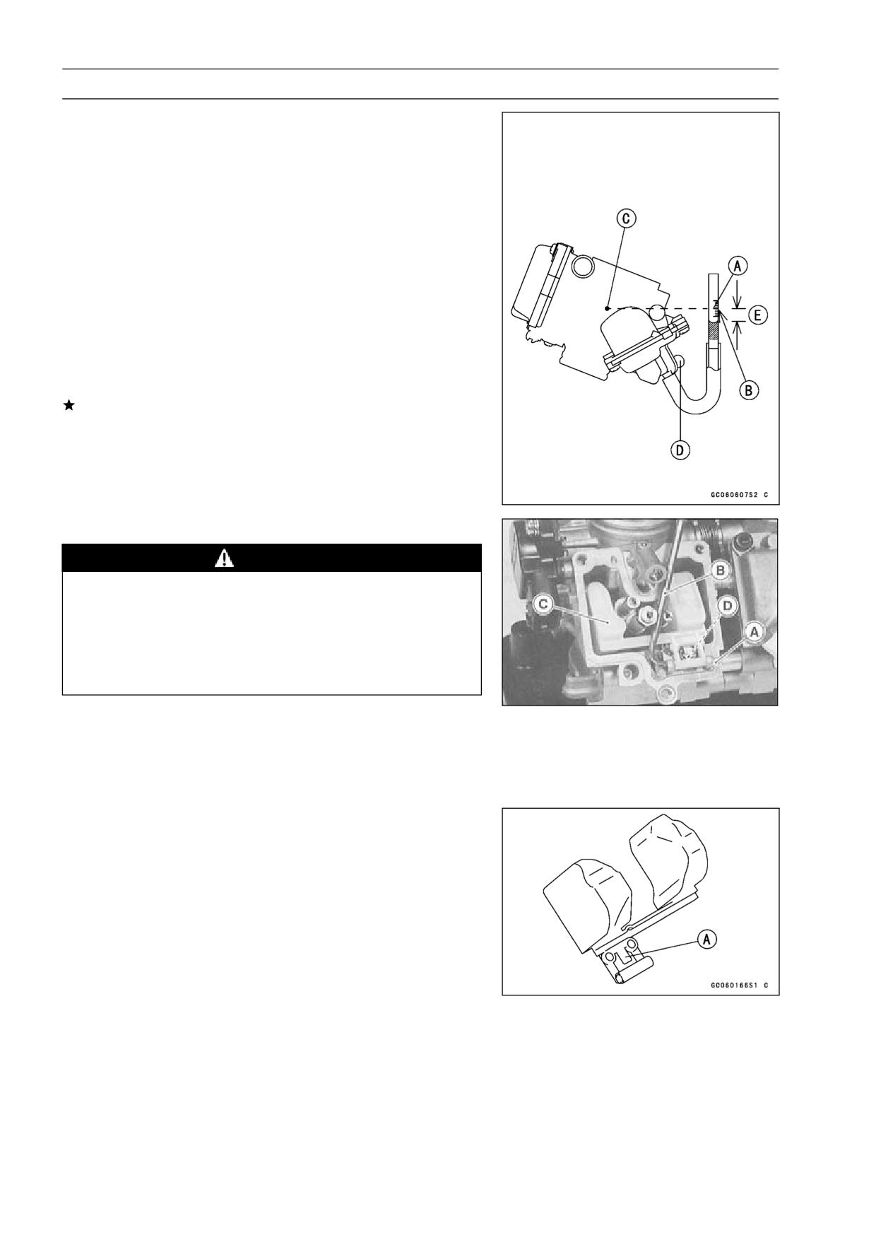
2-10 FUEL SYSTEM
Carburetors
Wait until the fuel level in the gauge settles.
•
Keeping the gauge vertical, align the "middle" line with the
•
mark.
NOTE
○Do not lower the "middle" line below the mark of the
carburetor body. If the gauge is lowered and then raised
again, the fuel level measured shows somewhat higher
than the actual fuel level. If the gauge is lowered too
far, dump the fuel into a suitable container and start the
procedure over again.
Read the fuel level [E] in the gauge and compare to the
•
specification.
Screw in the carburetor drain plug.
•
Stop feeding and remove the fuel level gauge.
•
If the fuel level is incorrect, adjust it (see Service Fuel
Level Adjustment).
Service Fuel Level (below the mark on the carburetor
body)
Standard:
20.2 ±1 mm (0.80 ±0.04 in.)
Service Fuel Level Adjustment
WARNING
Gasoline is extremely flammable and can be ex-
plosive under certain conditions. Turn the ignition
switch OFF. Do not smoke. Make sure the area is
well-ventilated and free from any source of flame
or sparks; this includes any appliance with a pilot
light.
Remove the carburetor, and drain the fuel into a suitable
•
container.
Remove the float bowl.
•
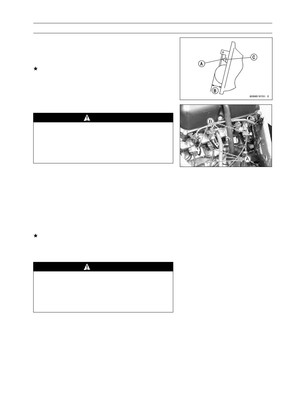
Slide out the pivot pin [A] with a suitable tool [B], and
•
remove the float [C] and float valve needle [D].
Bend the tang [A] on the float arm very slightly to change
•
the float height. Increasing the float height lowers the fuel
level and decreasing the float height raises the fuel level.
Float Height
Standard:
7 ±2 mm (0.28 ±0.08 in.)
FUEL SYSTEM 2-11
Carburetors
NOTE
○Do not push the needle rod [A] in during the float height
measurement [B].
Assemble the carburetor, and recheck the fuel level.
•
If the fuel level cannot be adjusted by this method, the
float or the float valve [C] is damaged.
Fuel System Cleanliness Inspection
WARNING
Gasoline is extremely flammable and can be ex-
plosive under certain conditions. Turn the ignition
switch OFF. Do not smoke. Make sure the area is
well-ventilated and free from any source of flame
or sparks; this includes any appliance with a pilot
light.
Remove the fuel tank (see Fuel Tank Removal)
•
Connect a suitable hose [A] to the fitting at the bottom of
•
each carburetor float bowl.
Run the lower ends of the hoses into a suitable container.
•
Turn out each drain plug [B] a few turns and drain the float
•
bowls.
Special Tool - Carburetor Drain Plug Wrench, Hex
3:
57001-1269
Check to see if water or dirt comes out.
•
Tighten the drain plugs.
•
If any water or dirt appears during the above inspection,
clean the fuel system (see Carburetor Cleaning and Fuel
Tank Cleaning).
Carburetor Removal
WARNING
Gasoline is extremely flammable and can be ex-
plosive under certain conditions. Turn the ignition
switch OFF. Do not smoke. Make sure the area is
well-ventilated and free from any source of flame
or sparks; this includes any appliance with a pilot
light.
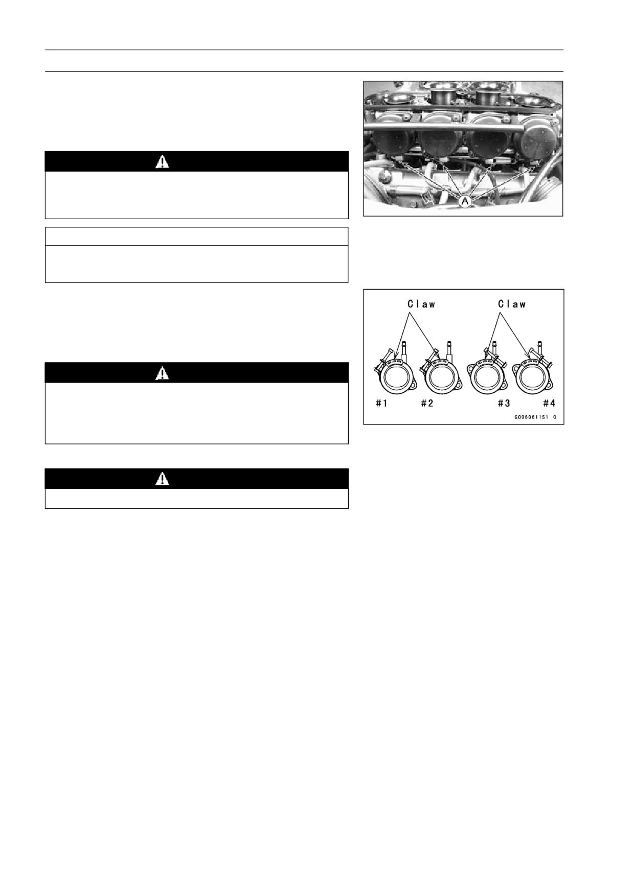
Drain the coolant (For the other than US & CA models,
•
see Cooling System chapter)
Remove:
•
Seats (see Frame chapter)
Fuel Tank (see Fuel Tank Removal)
Air Cleaner Housing (see Air Cleaner Housing Removal)
Vent Hose
Fuel Hose
Coolant Hoses (For the other than US & CA Models)
Throttle Sensor Connector
Fuel Cut Valve Connectors (CAL and H Model)
2-12 FUEL SYSTEM
Carburetors
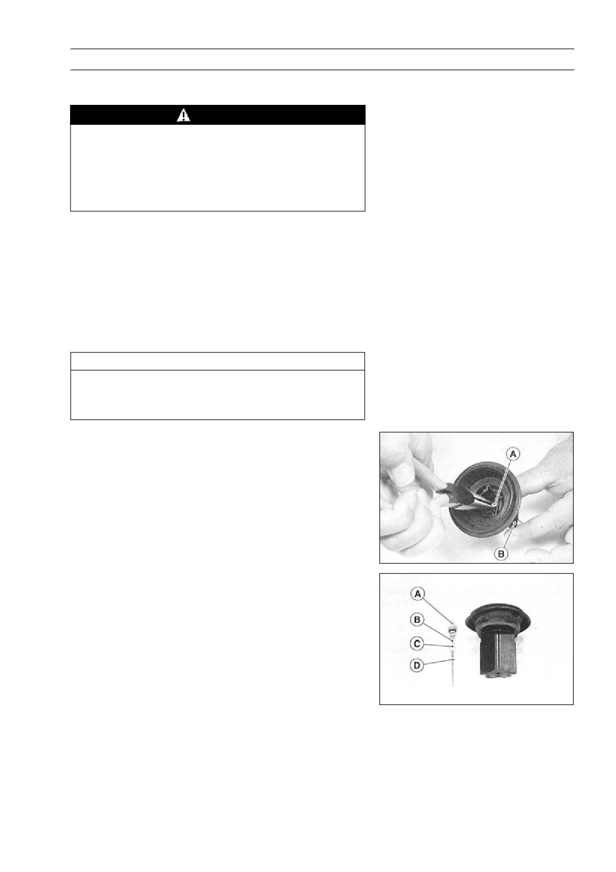
Loosen the carburetor clamp screws [A], and remove the
•
carburetors.
Remove the throttle cable ends and choke cable.
•
Stuff pieces of lint-free, clean cloth into the carburetor
•
holders to keep dirt out of the engine.
WARNING
If dirt or dust is allowed to pass through into the
carburetor, the throttle may become stuck, possibly
causing an accident.
CAUTION
If dirt gets through into the engine, excessive en-
gine wear and possibly engine damage will occur.
Carburetor Installation
Route the cables, harness, and hoses correctly (see Gen-
•
eral Information chapter).
Tighten the clamps for the carburetor holders at the posi-
•
tion in the figure.
WARNING
Be sure to install the holder clamp screws in the di-
rection shown. Or, the screws could come in con-
tact with the throttle linkage resulting in unsafe rid-
ing condition.
Check fuel leakage from the carburetors.
•
WARNING
Fuel spilled from the carburetors is hazardous.
Adjust the following items if necessary.
•
Idle Speed
Carburetor Synchronization
Throttle Cables
Choke Cable
FUEL SYSTEM 2-13
Carburetors
Carburetor Disassembly
Remove the carburetors.
•
WARNING
Gasoline is extremely flammable and can be ex-
plosive under certain conditions. Turn the ignition
switch OFF. Do not smoke. Make sure the area is
well-ventilated and free from any source of flame
or sparks; this includes any appliance with a pilot
light.
NOTE
○Carburetor can be disassembled in the joined state.
For the US model, remove the pilot screw plug as follows:
•
punch a hole in the plug and pry there with an awl or other
suitable tool.
Turn in the pilot screw and count the number of turns until
•
it seats fully but not tightly, and then remove the screw.
This is to set the screw to its original position when as-
sembling.
CAUTION
During carburetor disassembly, be careful not to
damage the diaphragm. Never use a sharp edge to
remove the diaphragm.
When removing the jet needle, pull straight out the holder
•
[A] from the vacuum piston [B].
○Remove:
Holder [A]
Spring [B]
Washer [C]
Jet Needle [D]
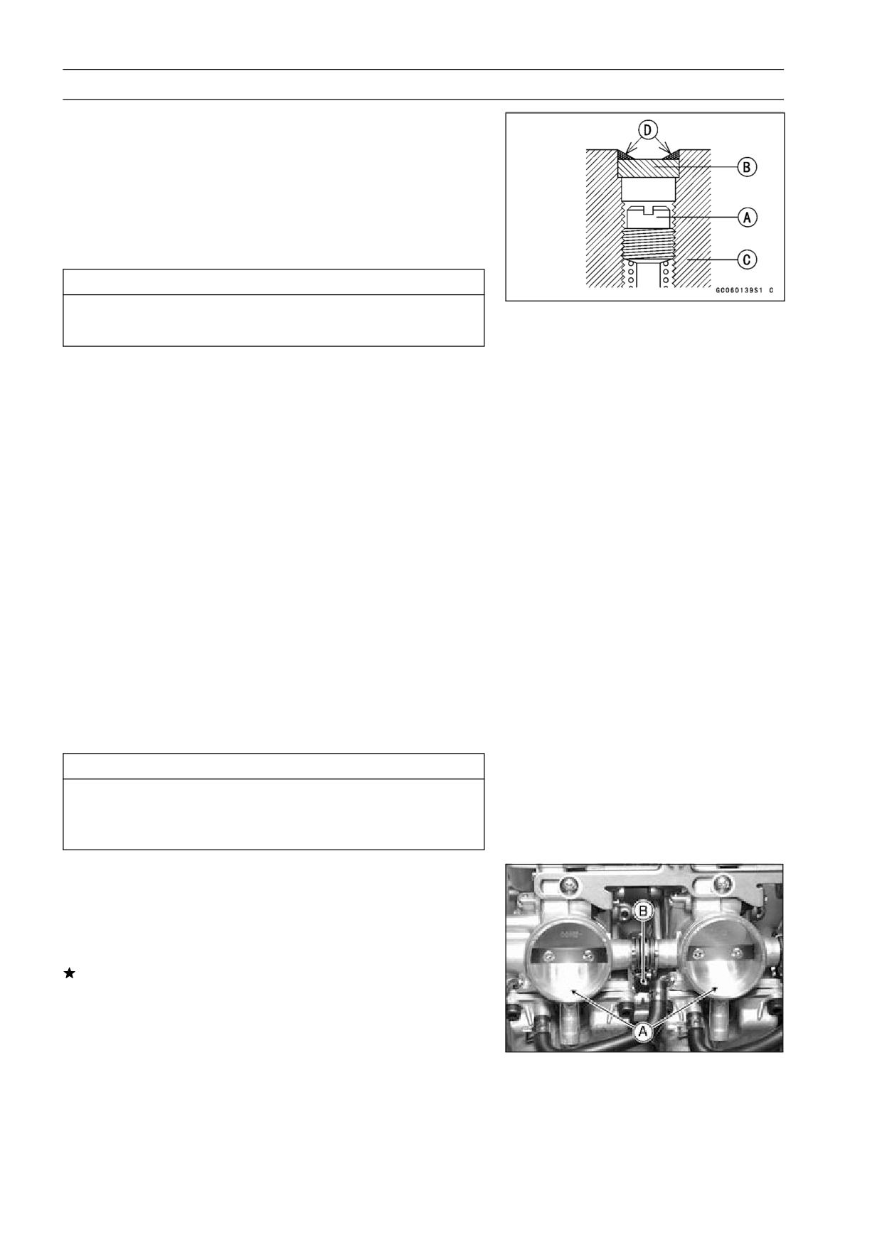
2-14 FUEL SYSTEM
Carburetors
Carburetor Assembly
Turn in the pilot screw [A] fully but not tightly, and then
•
back it out the same number of turns counted during dis-
assembly.
For the US model, install the pilot screw plug as follows:
•
install a new plug [B] in the pilot screw hole of the car-
buretor body [C], and apply a small amount of a bonding
agent [D] to the circumference of the plug to fix the plug.
CAUTION
Do not apply too much bonding agent to the plug or
the pilot screw itself may be fixed.
○Set the float height as specified (see Service Fuel Level
Adjustment).
After installing the upper chamber cover, check that the
•
vacuum piston slides up and down smoothly without bind-
ing in the carburetor bore.
Carburetor Separation
Remove the carburetor (see Carburetor Removal).
•
Read the WARNING in the carburetor disassembly.
•
Mark carburetor locations so that the carburetors can be
•
installed in their original positions.
Carburetor Joining
The center lines of the carburetor bores must be parallel
•
both horizontally and vertically. If they are not, loosen
the mounting screws and align the carburetors on a flat
surface.
Retighten the mounting screws.
•
After installing the choke mechanism, check to see that
•
the starter plunger lever slides right to left smoothly with-
out abnormal friction.
CAUTION
Fuel mixture trouble could result if the starter
plunger does not seat properly in its rest position
after the choke lever is returned.
Visually synchronize the throttle (butterfly) valves.
•
○Check to see that all throttle valves open and close
smoothly without binding when turning the pulley.
○Visually check the clearance [A] between the throttle
valve and the carburetor bore in each carburetor.
If there is a difference between any two carburetors, turn
the balance adjusting screw [B] to obtain the same clear-
ance.
Install the carburetors (see Carburetor Installation).
•
Adjust the synchronization (see Synchronization Adjust-
•
ment).
FUEL SYSTEM 2-15
Carburetors
Carburetor Cleaning
WARNING
Clean the carburetors in a well-ventilated area, and
take care that there is no sparks or flame anywhere
near the working area; this includes any appliance
with a pilot light. Because of the danger of highly
flammable liquids, do not use gasoline or low flash
-point solvents to clean the carburetors.
CAUTION
Do not use compressed air on an assembled carbu-
retor, or the floats may be crushed by the pressure,
and the vacuum piston diaphragms may be dam-
aged.
Remove as many rubber or plastic parts from the
carburetor as possible before cleaning the carbure-
tor with a cleaning solution. This will prevent dam-
age to or deterioration of the parts.
The carburetor body has plastic parts that can-
not be removed. Do not use a strong carburetor
cleaning solution which could attack these parts;
instead, use a mild high flash-point cleaning solu-
tion safe for plastic parts.
Do not use wire or any other hard instrument to
clean carburetor parts, especially jets, as they may
be damaged.
Disassemble the carburetor.
•
Immerse all the metal parts in a carburetor cleaning solu-
•
tion.
Rinse the parts in water.
•
When the parts are clean, dry them with compressed air.
•
Blow through the air and fuel passages with compressed
•
air.
Assemble the carburetor.
•
Carburetor Inspection
WARNING
Gasoline is extremely flammable and can be ex-
plosive under certain conditions. Turn the ignition
switch OFF. Do not smoke. Make sure the area is
well-ventilated and free from any source of flame
or sparks; this includes any appliance with a pilot
light.
Remove the carburetors.
•
Before disassembling the carburetors, check the fuel level
•
(see Fuel Level Inspection).
If the fuel level is incorrect, inspect the rest of the carbu-
retor before correcting it.
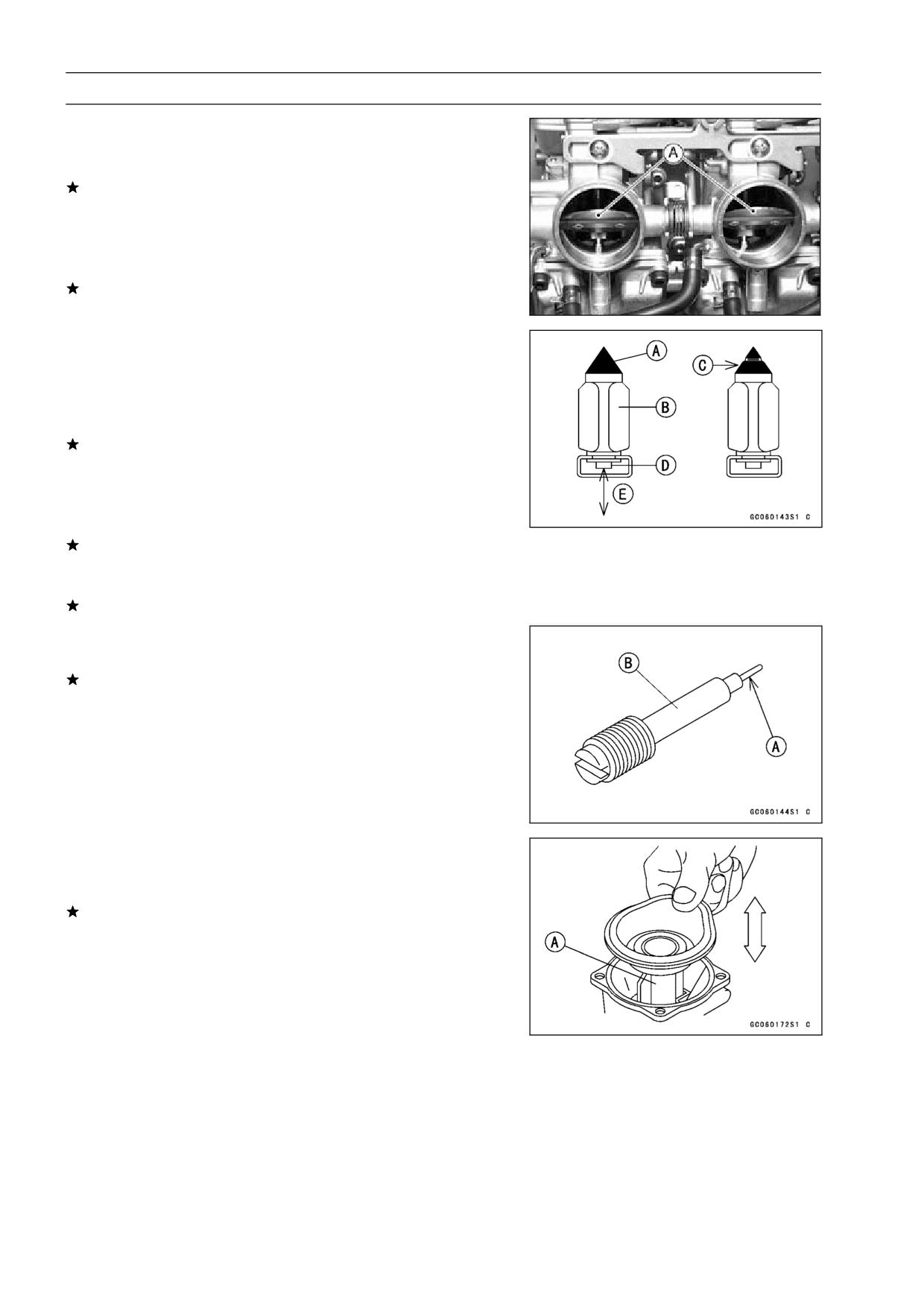
2-16 FUEL SYSTEM
Carburetors
Slide the starter plunger lever to the left and release it to
•
check that the starter plungers move smoothly and return
by spring tension.
If the starter plungers do not work properly, replace the
carburetors.
Turn the throttle cable pulley to check that the throttle but-
•
terfly valves [A] move smoothly and return by spring ten-
sion.
If the throttle valves do not move smoothly, replace the
carburetors.
Disassemble the carburetors.
•
Clean the carburetors.
•
Check that the O-rings on the float bowl and pilot screw
•
and the diaphragm on the vacuum piston are in good con-
dition.
If any of the O-rings or diaphragms are not in good con-
dition, replace them.
Check the plastic tip [A] of the float valve needle [B]. It
•
should be smooth, without any grooves, scratches, or
tears.
If the plastic tip is damaged [C], replace the needle.
Push the rod [D] in the other end of the float valve needle,
•
and then release it [E].
If the rod does not spring out, replace the needle.
Check the tapered portion [A] of the pilot screw [B] for
•
wear or damage.
If the pilot screw is worn or damaged on the tapered por-
tion, it will prevent the engine from idling smoothly. Re-
place it.
Check that the vacuum piston [A] moves smoothly in the
•
carburetor body. The surface of the piston must not be
excessively worn.
If the vacuum piston does not move smoothly, or if it is
very loose in carburetor body, replace the carburetor.
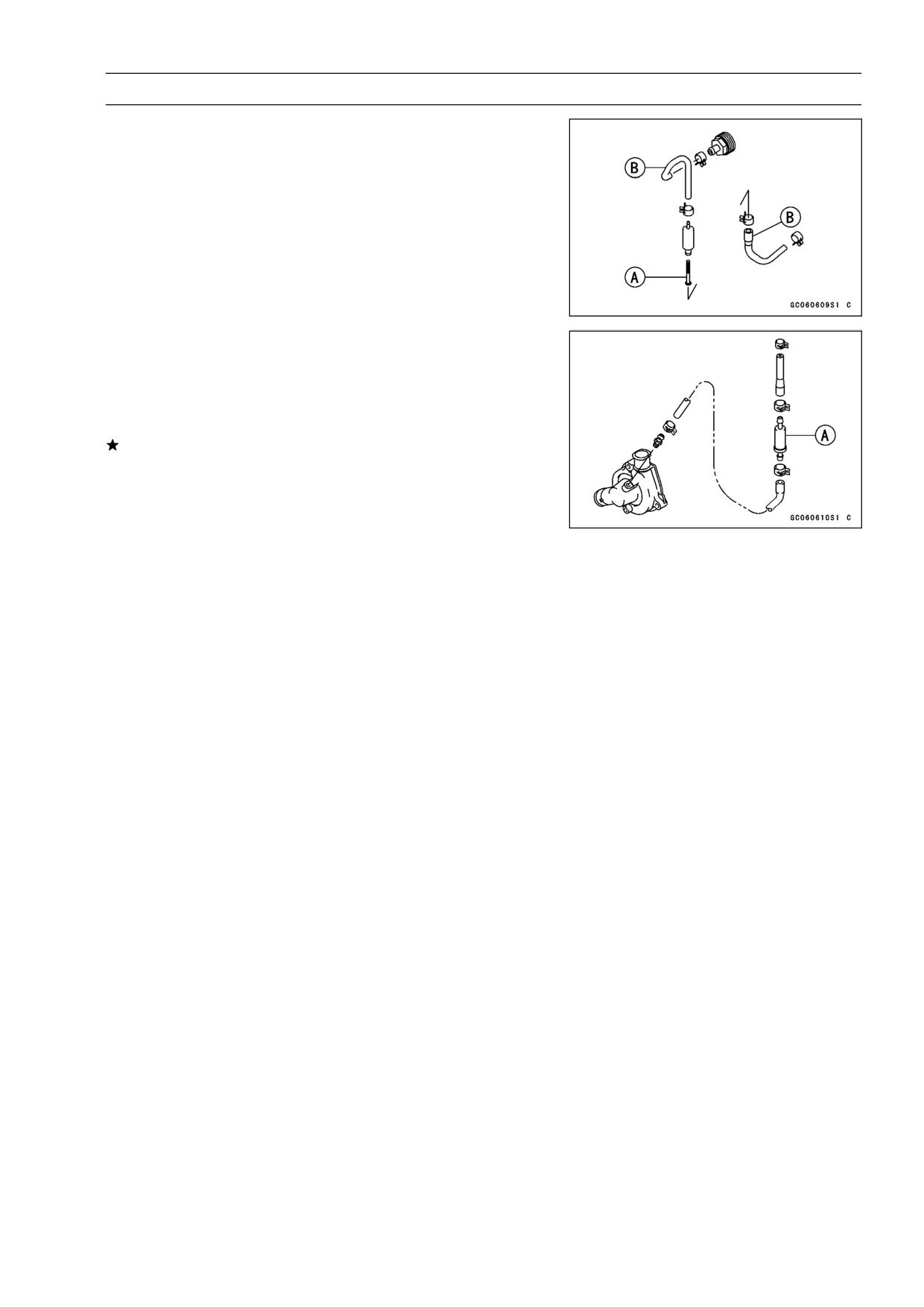
FUEL SYSTEM 2-17
Carburetors
Coolant Filter Cleaning (Other than United States and
Canada Models)
Before winter season starts, clean the filter of carburetor
system.
Remove the fuel tank (see Fuel Tank Removal).
•
Drain the coolant (see Cooling System chapter).
•
Remove the filter [A] from the cooling hoses [B] of carbu-
•
retor system.
Blow off dirt and sediment on the filter with compressed
•
air.
Coolant Valve Inspection (Other than United States
and Canada Models)
Drain the coolant (see Cooling System chapter).
•
Remove the coolant valve on the engine left side.
•
Inspect the coolant valve [A] at room temperature.
•
If the valve is closed, replace the valve with a new one.
○To check valve opening just blow through the valve.
Valve Closing Temperature (for reference)
Standard:
70°C (158°F) or more at 25 kPa (0.25 kg/cm²,
3.6 psi)
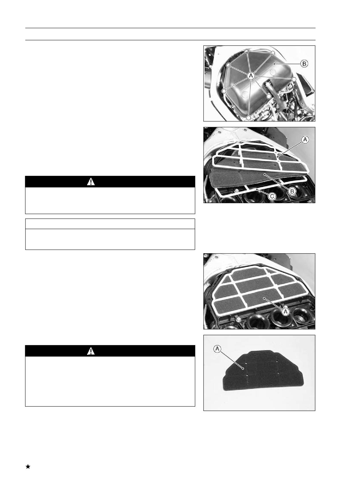
2-18 FUEL SYSTEM
Air Cleaner
Element Removal
Remove:
•
Seats (see Frame chapter)
Fuel Tank (see Fuel Tank Removal)
Upper Housing Mounting Bolts [A]
Upper Housing [B]
Remove the following parts as a unit.
•
Upper Plastic Holder [A]
Element [B]
Lower Plastic Holder [C]
Put a clean, lint-free towel on the air cleaner housing to
•
keep dirt or other foreign material from entering.
WARNING
If dirt or dust is allowed to pass through into the car-
buretors, the butterfly valves may become stuck,
possibly causing an accident.
CAUTION
If dirt gets through into the engine, excessive en-
gine wear and possibly engine damage will occur.
Element Installation
Install the element unit [A] with the foam element side
•
(gray) facing up.
Element Cleaning and Inspection
WARNING
Clean the element in a well-ventilated area, and
make sure that there are no sparks or flame any-
where near the working area.
Because of the danger of highly flammable liquids,
do not use gasoline or a low flash-point solvent to
clean the element.
Remove the air cleaner element [A] (see this chapter).
•
Clean the element in a bath of high flash-point solvent,
•
and then dry it with compressed air or by shaking it.
After cleaning, saturate a clean, lint-free towel with SE,
•
SF, or SG class SAE 30 oil and apply the oil to the element
by tapping the element outside with the towel.
Visually check the element for tears or breaks.
•
If the element has any tears or breaks, replace the ele-
ment.
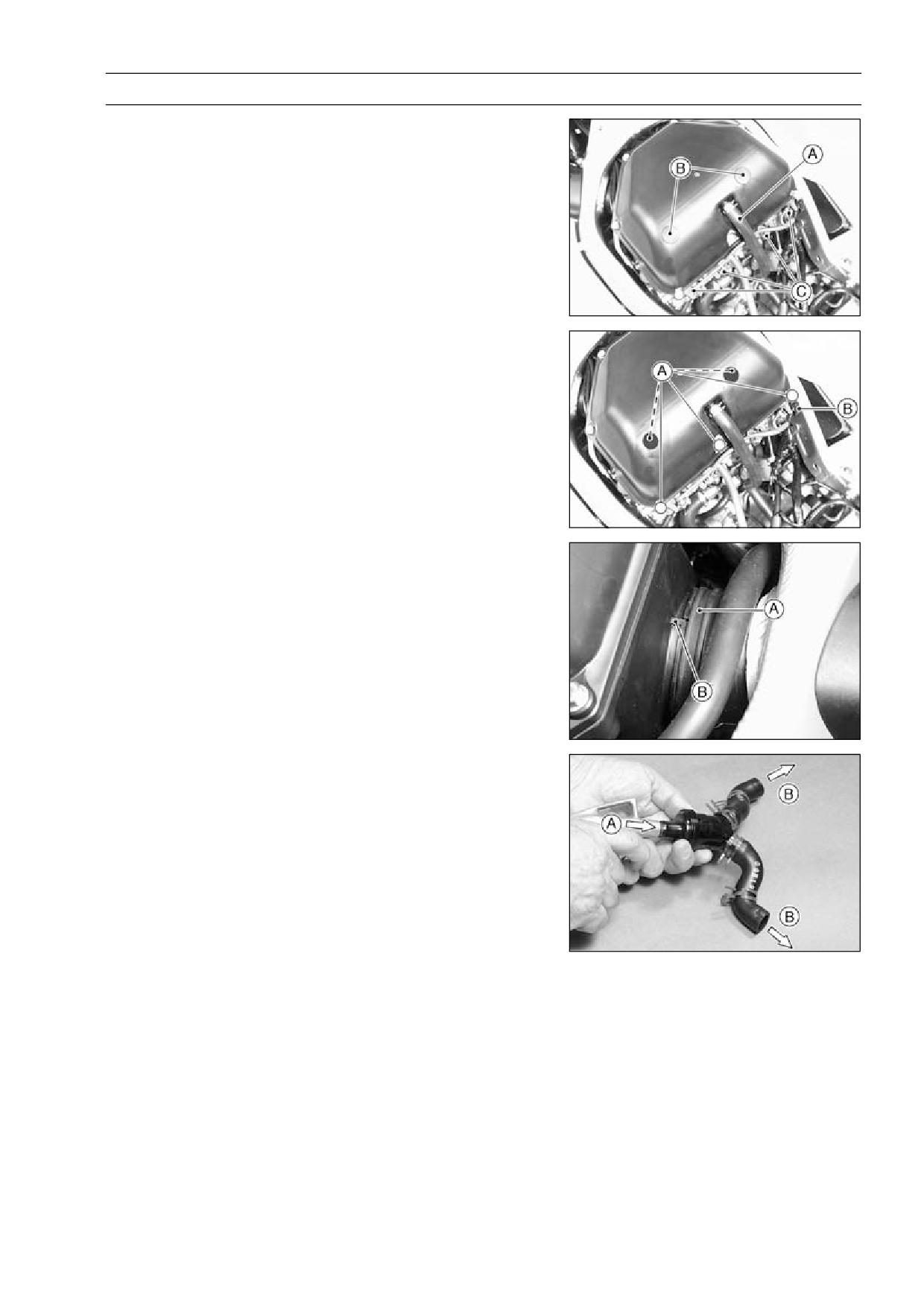
FUEL SYSTEM 2-19
Air Cleaner
Air Cleaner Housing Removal
Remove:
•
Seats (see Frame chapter)
Fuel Tank (see Fuel Tank Removal)
Engine Breather Hose [A]
Rubber Plugs [B]
Fuel Cut Valve Connectors [C] (California and H Models)
Remove:
•
Air Cleaner Housing Mounting Bolts [A]
Free the main harness from the clamp [B].
•
○Pull up the rear of the housing, and then remove it from
the air ducts.
Air Cleaner Housing Installation
Insert the housing into the air ducts [A] securely, and fit
•
the projection [B] of the housing in the recess of the air
ducts.
Tighten:
•
Housing Mounting Bolts
Be sure to fit the engine breather hose.
•
Install the rubber plugs in place.
•
Air Vent Filter Cleaning
Slide the clamps of air vent filter and remove the filter.
•
Clean the filter by directing a stream of compressed air
•
from clean side [A] to dirty side [B].
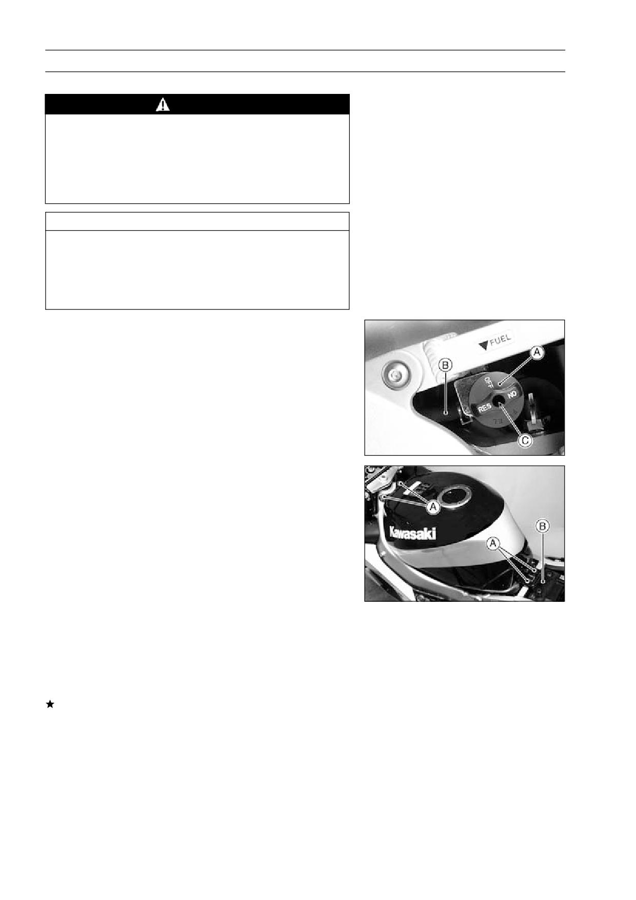
2-20 FUEL SYSTEM
Fuel Tank
Fuel Tank Removal
WARNING
Gasoline is extremely flammable and can be ex-
plosive under certain conditions. Turn the ignition
switch OFF. Do not smoke. Make sure the area is
well-ventilated and free from any source of flame
or sparks; this includes any appliance with a pilot
light.
CAUTION
For California model, if gasoline, solvent, water or
any other liquid enters the canister, the canister’s
vapor absorbing capacity is greatly reduced. If the
canister does become contaminated, replace it with
a new one.
Turn the fuel tap position lever [A] to the OFF position.
•
Remove:
•
Seats (see Frame chapter)
Evaporative Emission Hoses (California model)
Fuel Filter Hose [B]
Fuel Tap Position Lever Screws [C]
Remove:
•
Mounting Bolts [A]
Bracket [B]
Pull the rear part of the fuel tank right side to clear the fuel
•
tap, and then remove the fuel tank.
Fuel Tank Installation
Read the WARNING mentioned in Fuel Tank removal.
•
Route the hoses correctly (see General Information chap-
•
ter).
Be sure the hoses are clamped securely to prevent leaks.
•
Check the rubber dampers.
If any damper is damaged or deteriorated, replace it.
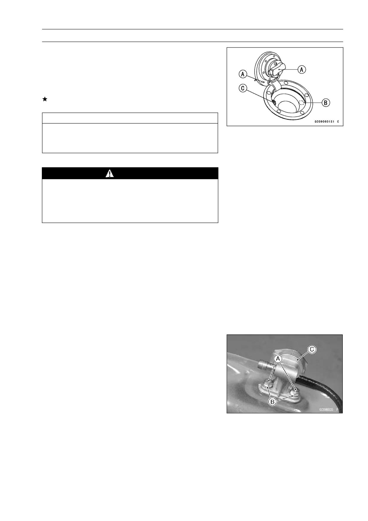
FUEL SYSTEM 2-21
Fuel Tank
Fuel Tank Inspection
Remove the hose(s) from the fuel tank, and open the tank
•
cap.
Check to see if the water drain pipe [B] (also the breather
•
pipe [C] for the California model) in the tank is not clogged.
Check the tank cap breather also.
If they are clogged, remove the tank and drain it, and then
blow the pipes free with compressed air.
CAUTION
Do not apply compressed air to the air vent holes
[A] in the tank cap. This could cause damage and
clogging of the labyrinth in the cap.
Fuel Tank Cleaning
WARNING
Clean the tank in a well-ventilated area, and take
care that there are no sparks or flame anywhere
near the working area. Because of the danger of
highly flammable liquids, do not use gasoline or low
flash- point solvents to clean the tank.
Remove the fuel tank and drain it.
•
Pour some high flash-point solvent into the fuel tank and
•
shake the tank to remove dirt and fuel deposits.
Pour high flash-point solvent through the tap in all lever
•
positions.
Pour the solvent out of the tank.
•
Remove the fuel tap from the tank (see Fuel Tap Re-
•
moval).
Clean the fuel tap filter screens in a high flash-point sol-
•
vent.
Dry the tank and screens with compressed air.
•
Install the tank filters in the tank.
•
Install the fuel tank (see Fuel Tank Installation).
•
Fuel Tap Removal
Remove the Fuel Tap Position Lever (see Fuel Tank Re-
•
moval).
Remove the fuel tank and drain it.
•
Remove:
•
Bolts [A]
Flat Washers [B]
Fuel Tap [C]
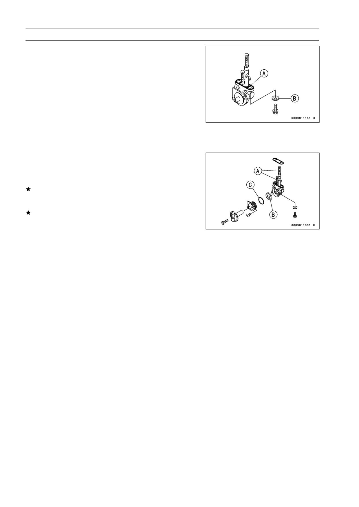
2-22 FUEL SYSTEM
Fuel Tank
Fuel Tap Installation
Be sure the O-rings [A] is in good condition to prevent
•
leaks.
Be sure the flat washers [B] are in good condition to pre-
•
vent leaks.
○Do not use steel washers in place of the flat washers,
because they will not seal the bolts properly and fuel will
leak.
Be sure to clamp the fuel hoses to the tap to prevent leaks.
•
Torque - Fuel Tap Bolts (with white washer): 2.5 N·m (0.25
kg·m, 22 in·lb)
Fuel Tap Bolts (with black washer): 4.9 N·m (0.50
kg·m, 43 in·lb)
Fuel Tap Inspection
Remove the fuel tap.
•
Check the fuel tap filter screens [A] for any breaks or de-
•
terioration.
If the fuel tap screens have any breaks or are deterio-
rated, they may allow dirt to reach the carburetor, causing
poor running. Replace the fuel tap.
If the fuel tap leaks, or allows fuel to flow when it is at OFF
position, replace the damaged gasket [B] or O-ring [C].
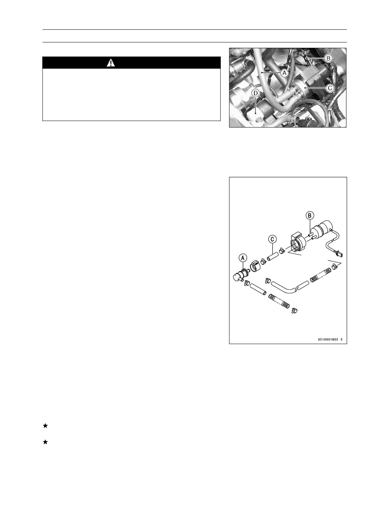
FUEL SYSTEM 2-23
Fuel Pump, Fuel Filter
Fuel Pump, Fuel Filter Removal
WARNING
Gasoline is extremely flammable and can be ex-
plosive under certain conditions. Turn the ignition
switch OFF. Do not smoke. Make sure the area is
well-ventilated and free from any source of flame
or sparks; this includes any appliance with a pilot
light.
Remove:
•
Seats (see Frame chapter)
Fuel Tank (see Fuel Tank Removal)
Fuel Hose [A]
Fuel Pump Lead Connector [B]
Remove the fuel pump [C] and fuel filter [D].
•
Fuel Pump, Fuel Filter Installation
Install the fuel filter so that the arrow [A] on it shows the
•
fuel flow from the fuel tank to the fuel pump.
Connect the fuel hose [C] from the fuel filter to the pump
•
fitting marked “INLET” [B].
Be sure to route the hoses so that they will not be kinked
•
or stretched.
Fuel Pump Inspection
Refer to the Electrical System chapter.
•
Fuel Filter Inspection
Remove:
•
Seats (see Frame chapter)
Fuel Tank (see Fuel Tank Removal)
Band
Visually inspect the fuel filter.
•
If the filter is clear with no signs of dirt or other contami-
nation, it is not necessary to replace it.
If the filter is dark or looks dirty, replace it. Also, check the
rest of the fuel system for contamination.
2-24 FUEL SYSTEM
Evaporative Emission Control System (California Model Only)
The Evaporative Emission Control System routes fuel va-
pors from the fuel system into the running engine or stores
the vapors in a canister when the engine is stopped. Al-
though no adjustments are required, a thorough visual in-
spection must be made at the intervals specified by the Pe-
riodic Maintenance Chart.
Parts Removal/Installation
WARNING
Gasoline is extremely flammable and can be ex-
plosive under certain conditions. Turn the ignition
switch OFF. Do not smoke. Make sure the area is
well-ventilated and free from any source of flame
or sparks; this includes any appliance with a pilot
light.
CAUTION
If gasoline, solvent, water or any other liquid enters
the canister, the canister’s vapor absorbing capac-
ity is greatly reduced. If the canister does become
contaminated, replace it with a new one.
To prevent the gasoline from flowing into or out of the
•
canister, hold the separator perpendicular to the ground.
Connect the hoses according to the diagram of the sys-
•
tem. Make sure they do not get pinched or kinked.
Route hoses with a minimum of bending so that the air or
•
vapor will not be obstructed.
Be sure to plug the return hose to prevent fuel spilling
•
before fuel tank removal.
WARNING
When removing the fuel tank, be careful not to spill
the gasoline through the return hose. Spilled fuel is
hazardous.
If liquid gasoline flows into the breather hose, remove the
hose and blow it clean with compressed air.
Hose Inspection
Check that the hoses are securely connected.
•
Replace any kinked, deteriorated or damaged hoses.
•
Separator Inspection
Remove the seats (see Frame chapter).
•
Disconnect the hoses from the liquid/vapor separator, and
•
remove the separator from the motorcycle.
Visually inspect the separator for cracks and other dam-
•
age.
If the separator has any cracks or is badly damaged, re-
place it with a new one.
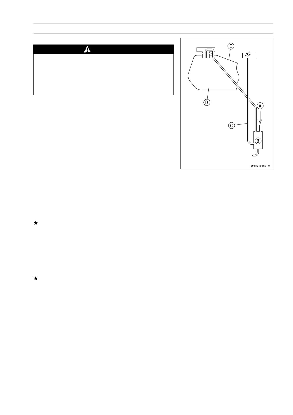
FUEL SYSTEM 2-25
Evaporative Emission Control System (California Model Only)
Separator Operation Test
WARNING
Gasoline is extremely flammable and can be ex-
plosive under certain conditions. Turn the ignition
switch OFF. Do not smoke. Make sure the area is
well-ventilated and free from any source of flame
or sparks; this includes any appliance with a pilot
light.
Connect the hoses to the separator, and install the sepa-
•
rator on the motorcycle.
Disconnect the breather hose from the separator, and in-
•
ject about 20 mL of gasoline [A] into the separator [B]
through the hose fitting.
Disconnect the fuel return hose [C] from the fuel tank [D].
•
Place the open end of the return hose into the container
•
and hold it with the same level of the tank top [E].
Start the engine, and let it idle.
•
If the gasoline in the separator comes out of the hose, the
separator works well. If it does not, replace the separator
with a new one.
Canister Inspection
Remove the seats and seat cover (see Frame chapter).
•
Remove the canister, and disconnect the hoses from the
•
canister.
Visually inspect the canister for cracks and other damage.
•
If the canister has any cracks or bad damage, replace it
with a new one.
NOTE
○The canister is designed to work well through the motor-
cycle’s life without any maintenance if it is used under
normal conditions.
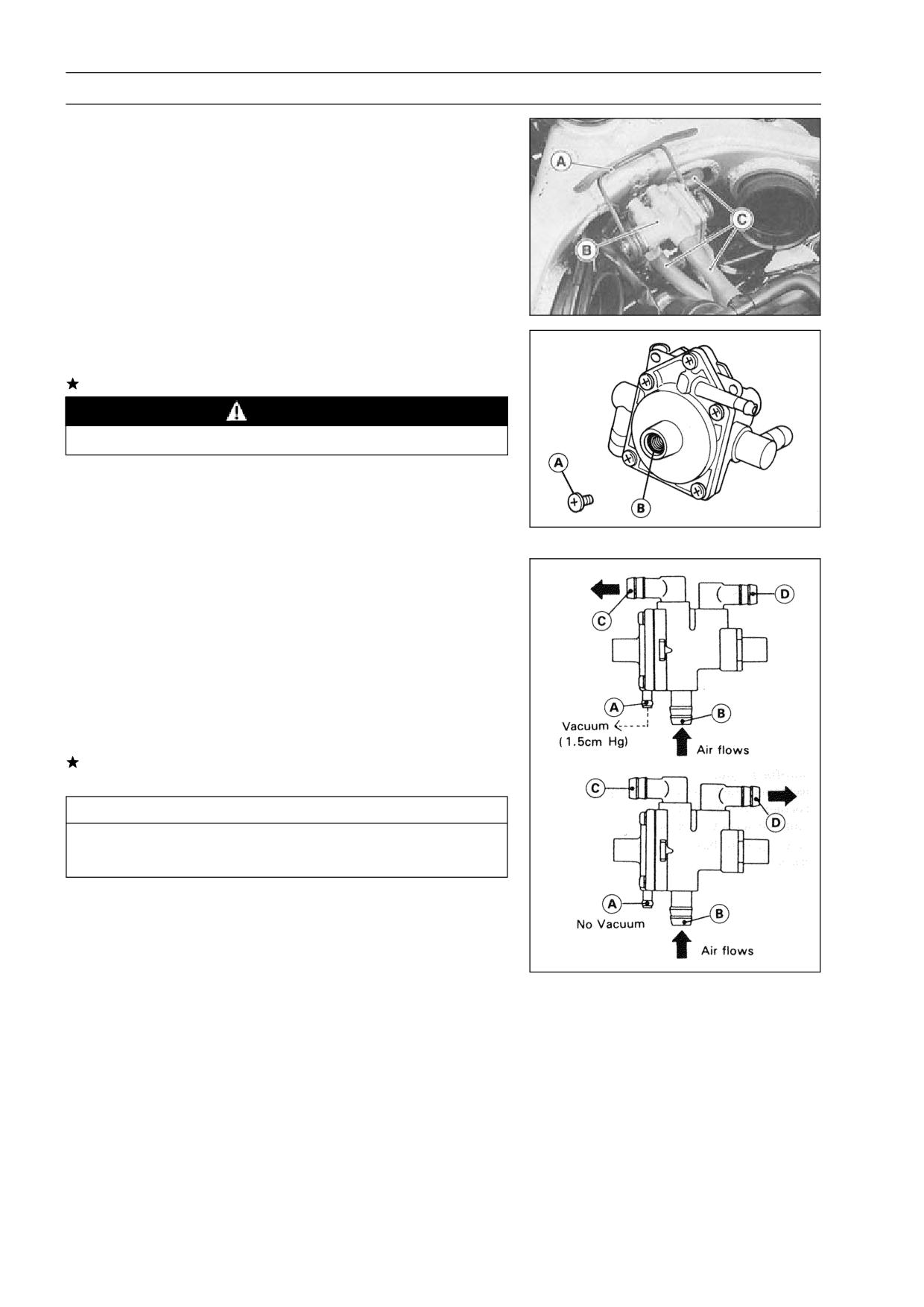
2-26 FUEL SYSTEM
Evaporative Emission Control System (California Model Only)
Vacuum Valve Inspection
Remove:
•
Air Cleaner Housing (see Air Cleaner Housing Removal)
Bracket [A] and Vacuum Valve [B]
Vacuum Valve Hoses [C]
Remove the drain screw [A] from the bottom of the cham-
•
ber.
If any liquid accumulates in the chamber, drain it.
WARNING
The liquid may contain gasoline.
Replace the O-ring [B] with a new one.
•
After draining, install the drain screw with the O-ring.
•
Torque - Vacuum Valve Drain Screw: 1.0 N·m (0.10 kg·m, 9
in·lb)
Using a vacuum gauge and fork oil level gauge, inspect
•
the vacuum valve operation (see Vacuum Switch Valve
Test in Engine Top End chapter).
Special Tool - Fork Oil Level Gauge: 57001-1290
○When applying vacuum (1.5 cmHg) to the vacuum sens-
ing fitting [A], air flows from pipe [B] to pipe [C], and vice
versa.
○When stopping applying vacuum, air flows from pipe [B]
to pipe [D], and vice versa.
If the vacuum valve does not operate as described, re-
place it with a new one.
CAUTION
Do not use compressed air during the valve check,
or the vacuum valve may be damaged.
COOLING SYSTEM 3-1
Cooling System
Table of Contents
3
Exploded View
3-2
Specifications
3-3
Coolant Flow Chart
3-4
Coolant
3-6
Coolant Deterioration Inspection
3-6
Coolant Level Inspection
3-6
Coolant Draining
3-6
Coolant Filling
3-7
Pressure Testing
3-8
Cooling System Flushing
3-9
Coolant Filter Cleaning
3-9
Water Pump
3-10
Water Pump Removal
3-10
Water Pump Installation
3-10
Water Pump Inspection
3-10
Radiator, Radiator Fan
3-11
Radiator and Radiator Fan Removal
3-11
Radiator Inspection
3-12
Radiator Cap Inspection
3-12
Thermostat
3-13
Thermostat Removal
3-13
Thermostat Installation
3-13
Thermostat Inspection
3-13
Hose and Pipes
3-14
Hose Installation
3-14
Hose Inspection
3-14
Radiator Fan Switch, Water Temperature Sensor
3-15
Radiator Fan Switch, Water Temperature Sensor Removal
3-15
Radiator Fan Switch, Water Temperature Sensor Installation
3-15
Radiator Fan Switch, Water Temperature Sensor Inspection
3-15
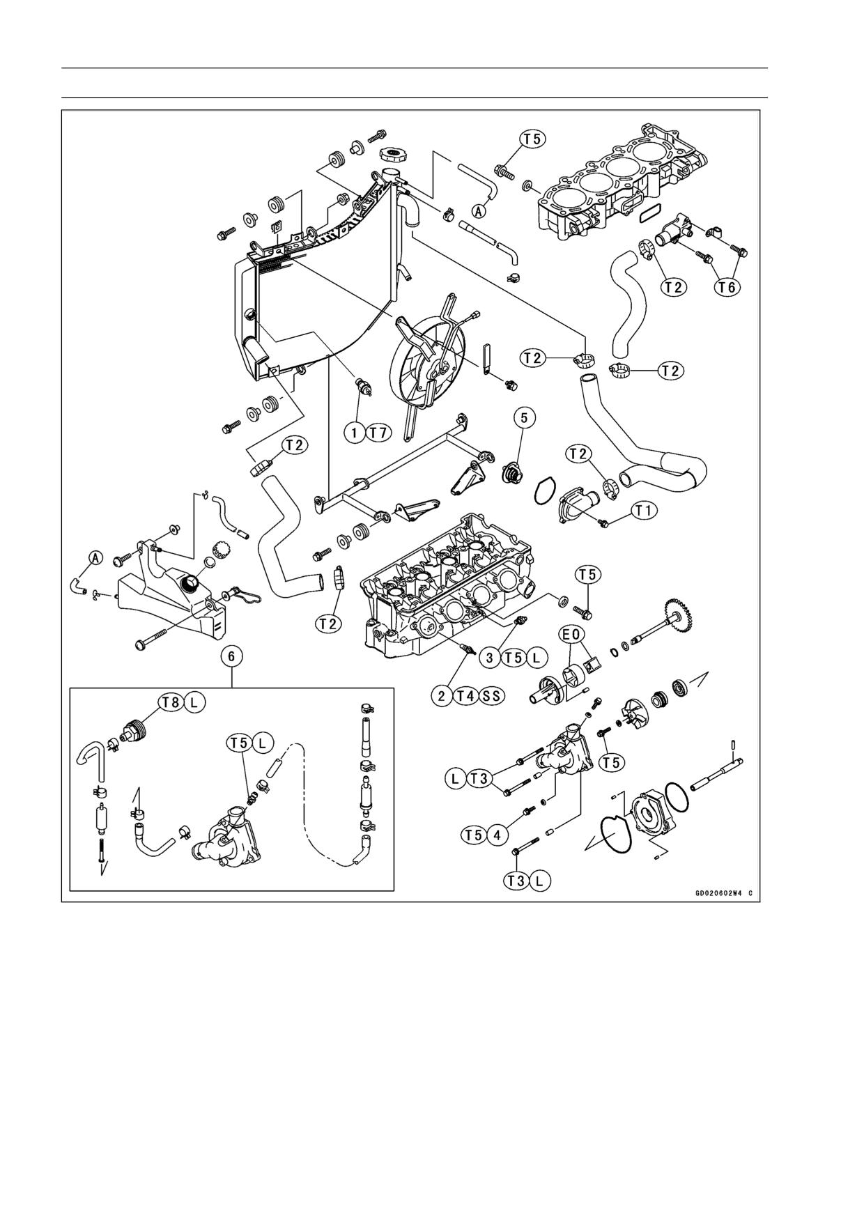
3-2 COOLING SYSTEM
Exploded View
1. Radiator Fan Switch
T3: 12 N·m (1.2 kgf·m, 104 in·lb)
2. Water Temperature Sensor
T4: 7.8 N·m (0.80 kgf·m, 69 in·lb)
3. Coolant By-pass Fitting
T5: 9.8 N·m (1.0 kgf·m, 87 in·lb)
4. Drain Plug
T6: 11 N·m (1.1 kgf·m, 95 in·lb)
5. Thermostat
T7: 18 N·m (1.8 kgf·m, 13 ft·lb)
6. Cooling Hose Assy (other than US, CA
T8: 20 N·m (2.0 kgf·m, 14.5 ft·lb)
Models)
EO: Apply engine oil.
T1: 5.9 N·m (0.60 kgf·m, 52 in·lb)
L: Apply a non-permanent locking agent.
T2: 2.0 N·m (0.20 kgf·m, 17 in·lb)
SS: Apply silicone sealant.
CA: Canada
US: United States
COOLING SYSTEM 3-3
Specifications
Item
Standard
Coolant provided when shipping
Type
Permanent type of antifreeze (soft water and ethylene glycol
plus corrosion and rust inhibitor chemicals for aluminum
engines and radiators)
Color
Green
Mixed ratio
Soft water 50%, coolant 50%
Freezing point
-35°C (-31°F)
Total amount
2.3 L (2.43 US qt) (reserve tank full level including radiator
and engine)
Radiator cap
Relief pressure:
93 ∼ 123 kPa (0.95 ∼ 1.25 kgf/cm², 14 ∼ 18 psi)
Thermostat
Valve opening temperature
58 ∼ 62°C (136 ∼ 144°F)
Valve full opening lift
8 mm (0.32 in.) or more @75°C (167°F)
Sealant - Kawasaki Bond (Silicone Sealant): 56019-120
3-4 COOLING SYSTEM
Coolant Flow Chart
Permanent type antifreeze is used as a coolant to protect the cooling system from rust and corrosion.
When the engine starts, the water pump turns and the coolant circulates.
The thermostat is a wax pellet type which opens or closes with coolant temperature changes. The
thermostat continuously changes its valve opening to keep the coolant temperature at the proper level.
When coolant temperature is below 55°C (131°F), the thermostat closes so that the coolant flow is
restricted through the air bleeder hole, causing the engine to warm up more quickly. When coolant
temperature is 58 ∼ 62°C (136 ∼ 144°F), the thermostat opens and the coolant flows.
When the coolant temperature goes up beyond 96 ∼ 100°C (205 ∼ 212°F), the radiator fan switch
conducts to operate the radiator fan. The radiator fan draws air through the radiator core when there
is not sufficient air flow such as at low speeds. This increases up the cooling action of the radiator.
When the temperature is below 91°C (196°F), the fan switch opens and the radiator fan stops.
In this way, this system controls the engine temperature within narrow limits where the engine op-
erates most efficiently even if the engine load varies.
The system is pressurized by the radiator cap to suppress boiling and the resultant air bubbles
which can cause engine overheating. As the engine warms up, the coolant in the radiator and the
water jacket expands. The excess coolant flows through the radiator cap and hose to the reserve tank
to be stored there temporarily. Conversely, as the engine cools down, the coolant in the radiator and
the water jacket contracts, and the stored coolant flows back to the radiator from the reserve tank.
The radiator cap has two valves. One is a pressure valve which holds the pressure in the system
when the engine is running. When the pressure exceeds 93 ∼ 123 kPa (0.95 ∼ 1.25 kgf/m², 14 ∼ 18
psi) the pressure valve opens and releases the pressure to the reserve tank. As soon as pressure
escapes, the valve closes, and keeps the pressure at 93 ∼ 123 kPa (0.95 ∼ 1.25 kgf/m², 14 ∼ 18 psi).
When the engine cools down, another small valve (vacuum valve) in the cap opens. As the coolant
cools, the coolant contracts to form a vacuum in the system. The vacuum valve opens and allows the
coolant from the reserve tank to enter the radiator.
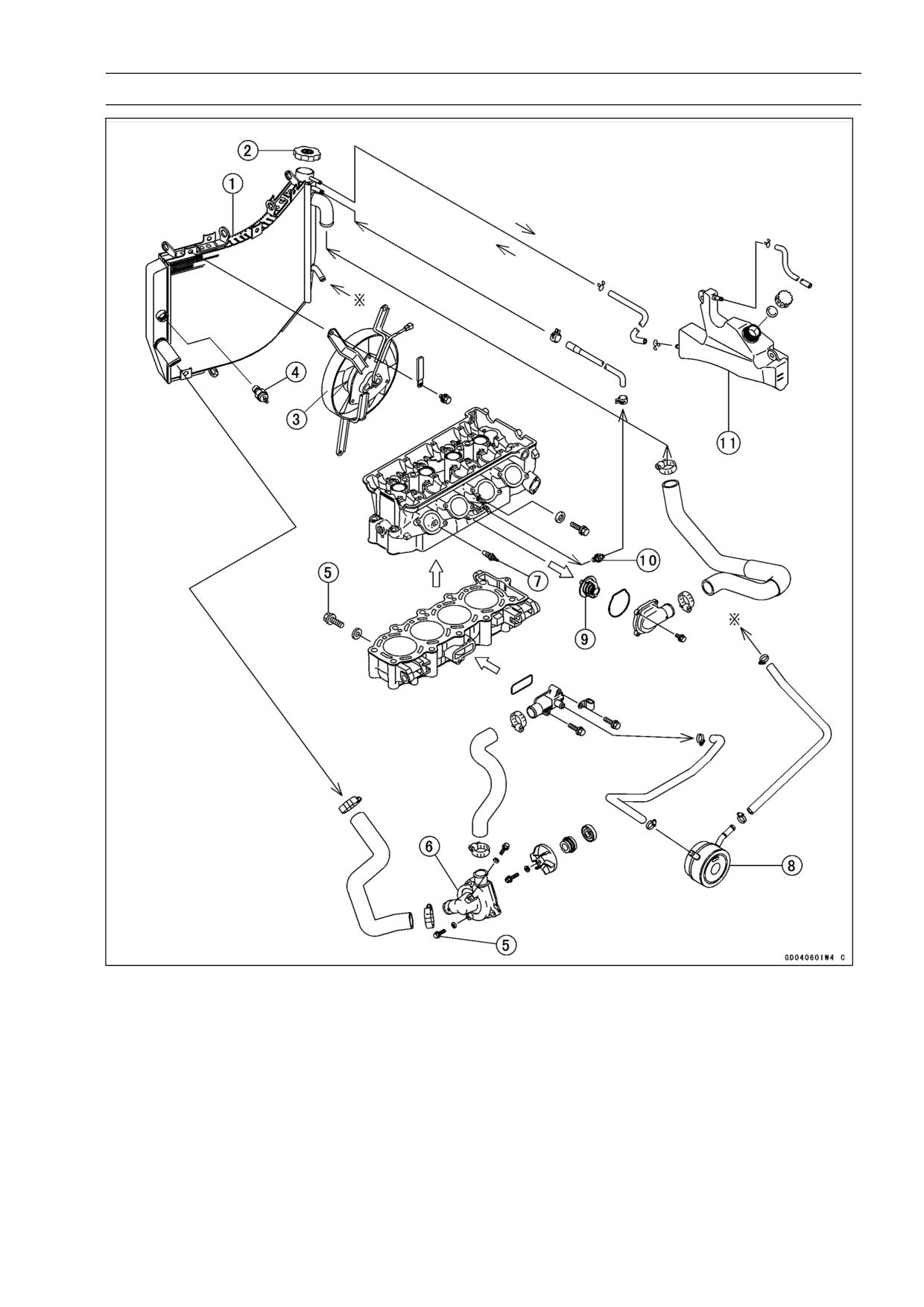
COOLING SYSTEM 3-5
Coolant Flow Chart
1. Radiator
5. Drain Plug
2. Radiator Cap
6. Water Pump
3. Radiator Fan
7. Water Temperature Sensor
4. Fan Switch
8. Oil Cooler
9. Thermostat
When the engine is cold, the thermostat is closed so that the coolant flow is restricted through
the air bleeder hole, causing the engine to warm up more quickly.
10. By-pass Fitting
The fitting is installed to bleed the air.
11. Reserver Tank
When the engine is very hot, the pressure valve in the radiator cap allows air and vapor to
escape into the reserve tank. When the engine cools down, the pressure drop draws the vacuum
valve (another small valve) open, admitting coolant from the reserve tank into the radiator.
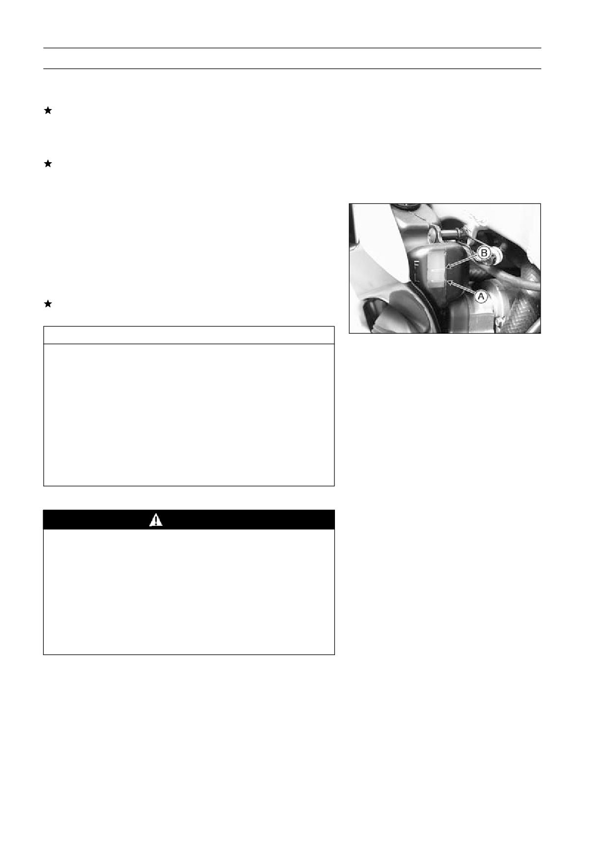
3-6 COOLING SYSTEM
Coolant
Coolant Deterioration Inspection
Visually inspect the coolant in the reserve tank.
•
If whitish cotton-like wafts are observed, aluminum parts
in the cooling system are corroded. If the coolant is
brown, iron or steel parts are rusting. In either case, flush
the cooling system.
If the coolant gives off an abnormal smell, check for a
cooling system leak. It may be caused by exhaust gas
leaking into the cooling system.
Coolant Level Inspection
NOTE
○Check the level when the engine is cold (room or ambi-
ent temperature).
Check the coolant level in the reserve tank with the mo-
•
torcycle held perpendicular.
If the coolant level is lower than the low level line [A], add
coolant to the full level line [B].
CAUTION
For refilling, add the specified mixture of coolant
and soft water. Adding water alone dilutes the
coolant and degrades its anticorrosion properties.
The diluted coolant can attack the aluminum en-
gine parts. In an emergency, soft water alone can
be added. But the diluted coolant must be returned
to the correct mixture ratio within a few days.
If coolant must be added often, or the reservoir tank
has run completely dry, there is probably leakage in
the cooling system. Check the system for leaks.
Coolant Draining
WARNING
To avoid burns, do not remove the radiator cap or
try to change the coolant when the engine is still
hot. Wait until it cools down. Coolant on tires will
make them slippery and can cause an accident
and injury. Immediately wipe up or wash away any
coolant that spills on the frame, engine, or other
painted parts.
Since coolant is harmful to the human body, do not
use for drinking.
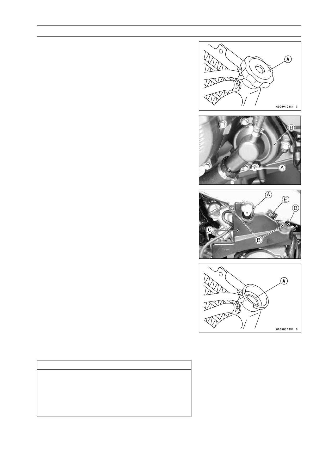
COOLING SYSTEM 3-7
Coolant
Remove:
•
Lower Fairing (see Frame chapter)
Radiator Cap [A]
Place a container under the drain plug [A] at the bottom
•
of the water pump cover [B].
Drain the coolant from the radiator and engine by remov-
•
ing the drain plug.
Remove:
•
Lower Fairing (see Frame chapter)
Hose [A]
Mounting Screws [B] and Reserve Tank [C]
Collar and Idle Speed Adjusting Screw Bracket [D]
Remove the cap [E] and pour the coolant into a container.
•
Coolant Filling
Remove:
•
Lower Fairing (see Frame chapter)
Tighten the drain plug.
•
Torque - Drain Plug: 9.8 N·m (1.0 kgf·m, 87 in·lb)
Fill the radiator up to the radiator filler neck [A] with
•
coolant, and install the radiator cap.
NOTE
○Pour in the coolant slowly so that it can expel the air
from the engine and radiator.
Fill the reserve tank up to the full level line with coolant,
•
and install the cap.
CAUTION
Soft or distilled water must be used with the an-
tifreeze (see below for antifreeze) in the cooling sys-
tem.
If hard water is used in the system, it causes scales
accumulation in the water passages, and consider-
ably reduces the efficiency of the cooling system.
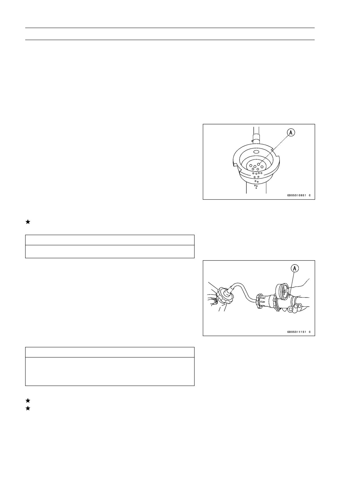
3-8 COOLING SYSTEM
Coolant
Water and Coolant Mixture Ratio (Recommended)
Soft Water
:
50%
Coolant
:
50%
Freezing Point
:
-35°C (-31°F)
Total Amount
:
2.3 L (2.43 US qt)
NOTE
○Choose a suitable mixture ratio by referring to the
coolant manufacturer’s directions.
Bleed the air from the cooling system as follows.
•
○Start the engine with the radiator cap removed and run it
until no more air bubbles [A] can be seen in the coolant.
○Tap the radiator hoses to force any air bubbles caught
inside.
○Stop the engine and add coolant up to the radiator filler
neck.
Install the radiator cap.
•
Start the engine, warm it up thoroughly until the radiator
•
fan turns on and then stop the engine.
Check the coolant level in the reserve tank after the en-
•
gine cools down.
If the coolant level is lower than the low level line, add
coolant to the full level line.
CAUTION
Do not add more coolant above the full level line.
Pressure Testing
Remove:
•
Lower Fairing (see Frame chapter)
Remove the radiator cap, and install a cooling system
•
pressure tester [A] on the filler neck.
NOTE
○Wet the cap sealing surfaces with water or coolant to
prevent pressure leaks.
Build up pressure in the system carefully until the pres-
•
sure reaches 123 kPa (1.25 kgf/cm², 18 psi).
CAUTION
During pressure testing, do not exceed the pres-
sure for which the system is designed. The maxi-
mum pressure is 123 kPa (1.25 kgf/cm², 18 psi).
Watch the gauge for at least 6 seconds.
•
If the pressure holds steady, the system is all right.
If the pressure drops and no external source is found,
check for internal leaks. Droplets in the engine oil indicate
internal leakage. Check the cylinder head gasket and the
water pump.
Remove the pressure tester, replenish the coolant, and
•
install the radiator cap.
COOLING SYSTEM 3-9
Coolant
Cooling System Flushing
Over a period of time, the cooling system accumulates
rust, scale, and lime in the water jacket and radiator. When
this accumulation is suspected or observed, flush the cool-
ing system. If this accumulation is not removed, it will clog
up the water passage and considerable reduce the effi-
ciency of the cooling system.
Drain the cooling system (see Coolant Draining).
•
Fill the cooling system with fresh water mixed with a flush-
•
ing compound.
CAUTION
Do not use a flushing compound which is harmful to
the aluminum engine and radiator. Carefully follow
the instructions supplied by the manufacturer of the
cleaning product.
Warm up the engine, and run it at normal operating tem-
•
perature for about ten minutes.
Stop the engine, and drain the cooling system.
•
Fill the system with fresh water.
•
Warm up the engine and drain the system.
•
Repeat the previous two steps once more.
•
Fill the system with a permanent type coolant and bleed
•
the air from the system (see Coolant Filling).
Coolant Filter Cleaning
Refer to the chapter of carburetor in Fuel System for the
cleaning procedures.
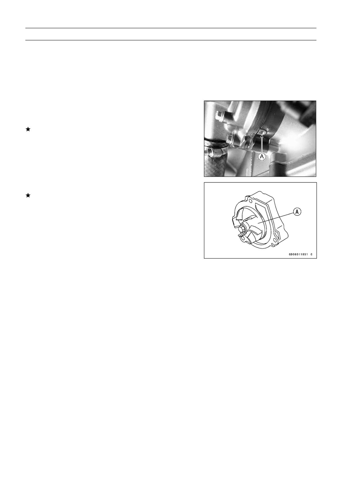
3-10 COOLING SYSTEM
Water Pump
Water Pump Removal
Refer to Oil Pump Removal in the Engine Lubrication Sys-
•
tem chapter.
Water Pump Installation
Refer to Oil Pump Installation in the Engine Lubrication
•
System chapter.
Water Pump Inspection
Check the drainage outlet passage [A] at the bottom of
•
the water pump body for coolant leaks.
If the mechanical seal is damaged, the coolant leaks
through the seal and drains through the passage. Re-
place the water pump unit.
Visually inspect the impeller [A].
•
If the surface is corroded, or if the blades are damaged,
replace the water pump unit.
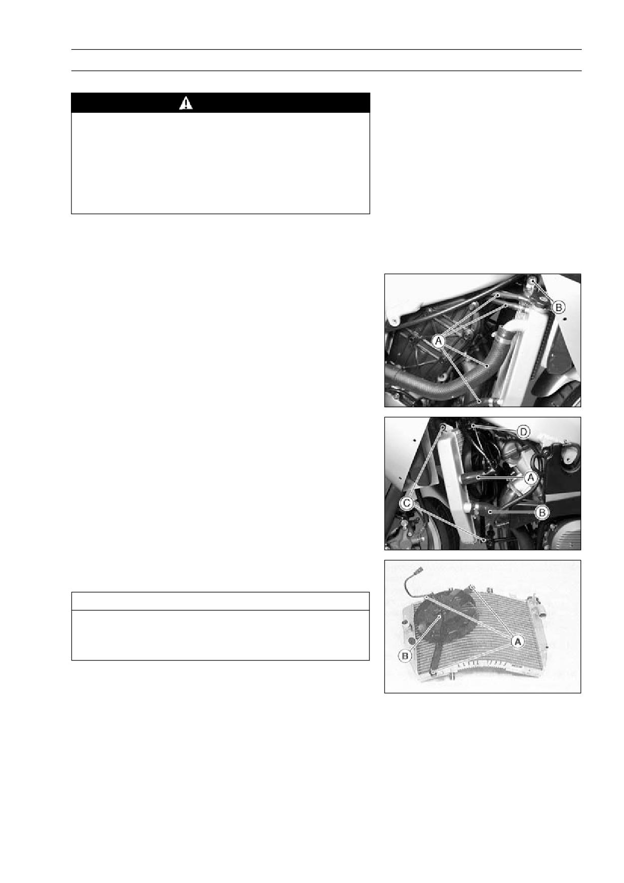
COOLING SYSTEM 3-11
Radiator, Radiator Fan
Radiator and Radiator Fan Removal
WARNING
The radiator fan is connected directly to the bat-
tery. The radiator fan may start even if the ignition
switch is off. NEVER TOUCH THE RADIATOR FAN
UNTIL THE RADIATOR FAN CONNECTOR IS DIS-
CONNECTED. TOUCHING THE FAN BEFORE THE
CONNECTOR IS DISCONNECTED COULD CAUSE
INJURY FROM THE FAN BLADES.
Remove:
•
Lower Fairings (see Frame chapter)
Coolant (see Coolant Draining)
Water Hoses [A]
Radiator Mounting Bolt [B]
Fan Switch Lead Connector [A]
Water Hose [B]
Radiator Mounting Bolts [C]
Radiator Fan Lead Connector [D]
Radiator
Radiator Fan Mounting Bolts [A]
Radiator Fan [B]
CAUTION
Do not touch the radiator core. This could damage
the radiator fins, resulting in loss of cooling effi-
ciency.
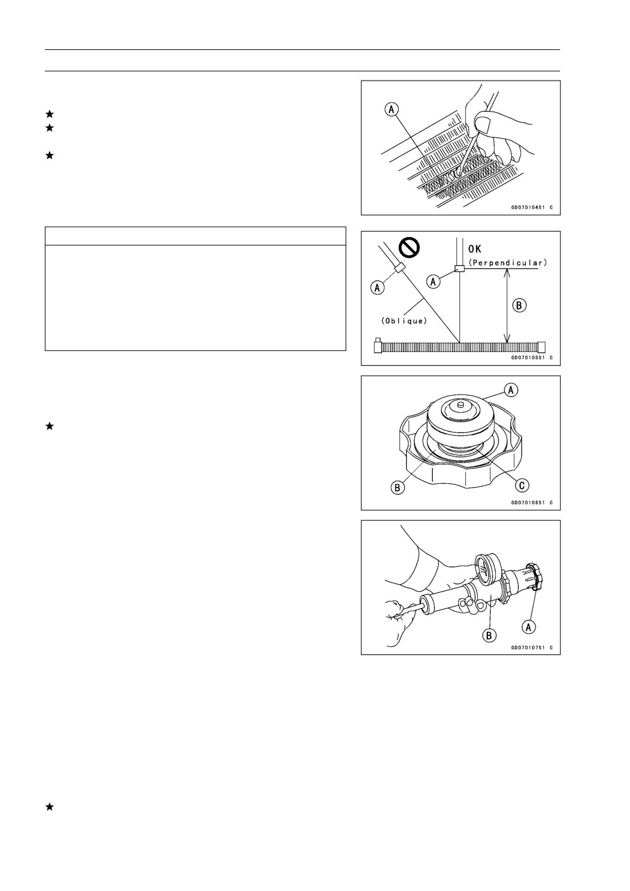
3-12 COOLING SYSTEM
Radiator, Radiator Fan
Radiator Inspection
Check the radiator core.
•
If there are obstructions to air flow, remove them.
If the corrugated fins [A] are deformed, carefully
straighten them.
If the air passages of the radiator core are blocked more
than 20% by unremovable obstructions or irreparably de-
formed fins, replace the radiator with a new one.
CAUTION
When cleaning the radiator with steam cleaner, be
careful of the following to prevent radiator damage.
Keep the steam gun [A] away more than 0.5 m (1.64
ft ) [B] from the radiator core.
Hold the steam gun perpendicular to the core sur-
face.
Run the steam gun following the core fin direction.
Radiator Cap Inspection
Check the condition of the top [A] and bottom [B] valve
•
seals and valve spring [C].
If any one of them shows visible damage, replace the cap
with a new one.
Install the cap [A] on a cooling system pressure tester [B].
•
NOTE
○Wet the cap sealing surfaces with water or coolant to
prevent pressure leaks.
Watching the pressure gauge, pump the pressure tester
•
to build up the pressure until the relief valve opens: the
gauge hand flicks downward. Stop pumping and measure
leak time at once. The relief valve must open within the
specified range in the table below and the gauge hand
must remain within the same range at least 6 seconds.
Radiator Cap Relief Pressure
93 ∼ 123 kPa (0.95 ∼ 1.25 kgf/cm²,14 ∼ 18
Standard:
psi)
If the cap cannot hold the specified pressure, or if it holds
too much pressure, replace it with a new one.
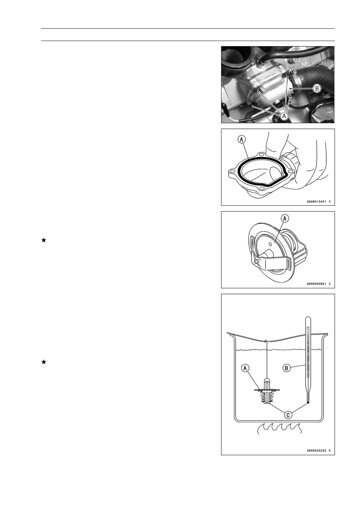
COOLING SYSTEM 3-13
Thermostat
Thermostat Removal
Remove:
•
Coolant (see Coolant Draining)
Seats (see Frame chapter)
Fuel Tank (see Fuel System chapter)
Thermostat Housing Cover Bolts [A]
Thermostat Housing Cover [B]
Thermostat
Thermostat Installation
Be sure to install the O-ring [A] on the housing cover.
•
Tighten the housing cover bolts.
•
Torque - Thermostat Housing Cover Bolts: 5.9 N·m (0.60
kgf·m, 52 in·lb)
Fill the radiator with coolant.
•
Thermostat Inspection
Remove the thermostat, and inspect the thermostat valve
•
[A] at room temperature.
If the valve is open, replace the thermostat with a new
one.
To check valve opening temperature, suspend the ther-
•
mostat [A] in a container of water and raise the tempera-
ture of the water.
○The thermostat must be completely submerged and must
not touch the container sides or bottom. Suspend an ac-
curate thermometer [B] in the water so that the heat sen-
sitive portions [C] are located in almost the same depth.
It must not touch the container, either.
If the measurement is out of the specified range, replace
the thermostat with a new one.
Thermostat Valve Opening Temperature
58 ∼ 62°C (136 ∼ 144°F)
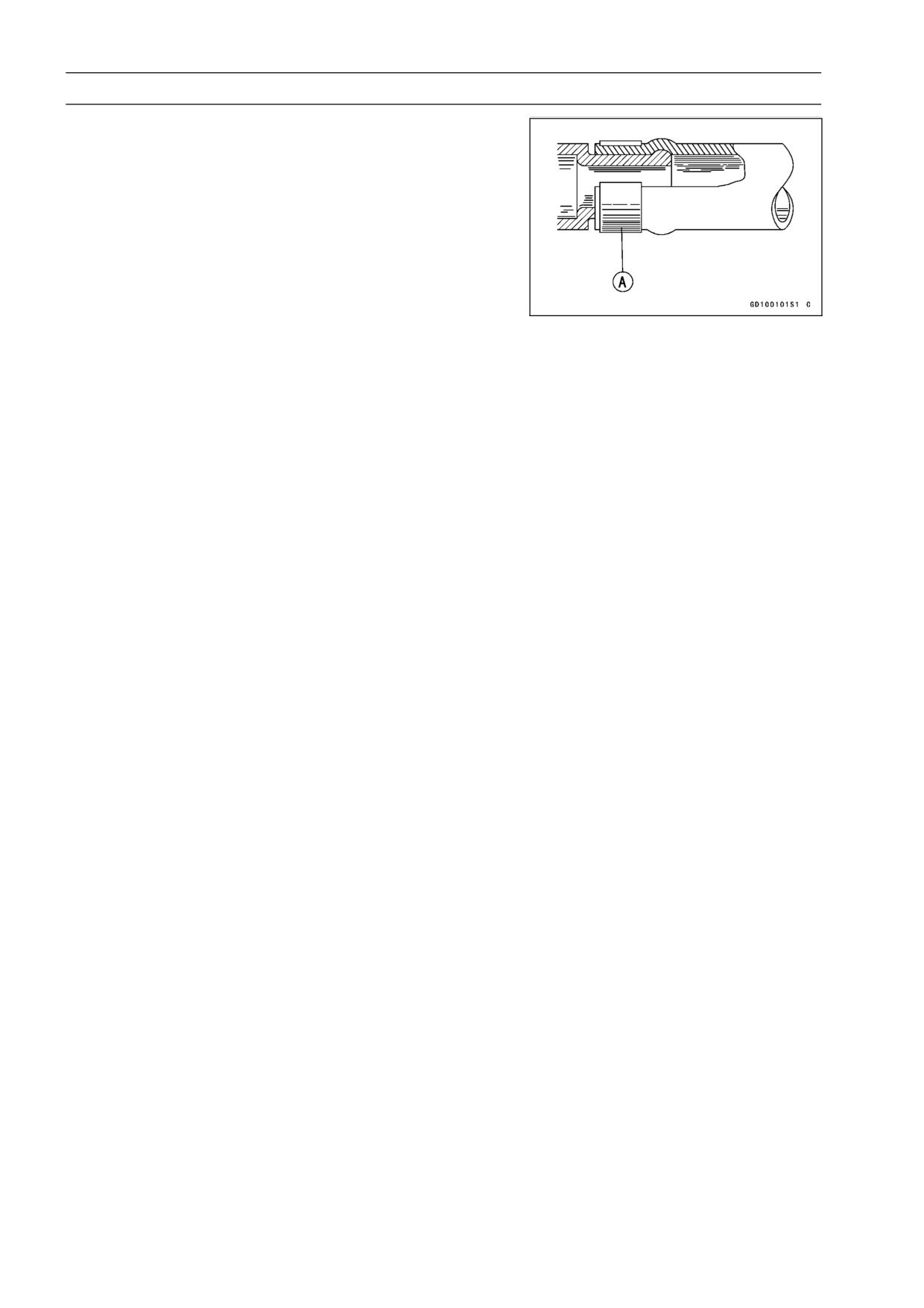
3-14 COOLING SYSTEM
Hose and Pipes
Hose Installation
Install the hoses and pipes being careful to follow bend-
•
ing direction or diameter. Avoid sharp bending, kinking,
flattening, or twisting.
Install the clamps [A] as near as possible to the hose end
•
to clear the raised rib or the fitting. This will prevent the
hoses from working loose.
○The clamp screws should be positioned correctly to pre-
vent the clamps from contacting anything.
Torque - Water Hose Clamp Screws: 2.0 N·m (0.20 kgf·m,
17 in·lb)
Hose Inspection
Visually inspect the hoses for signs of deterioration.
•
Squeeze the hoses. A hose should not be hard and
brittle, nor should it be soft to swollen.
Replace any damaged hoses.
•
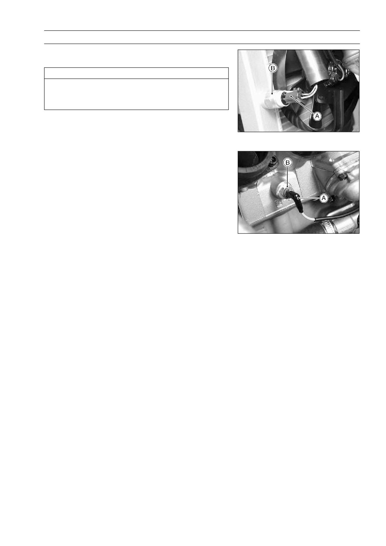
COOLING SYSTEM 3-15
Radiator Fan Switch, Water Temperature Sensor
Radiator Fan Switch, Water Temperature Sensor
Removal
CAUTION
The fan switch or the water temperature sensor
should never be allowed to fall on a hard surface.
Such a shock to their parts can damage them.
Drain the coolant (see Coolant Draining).
•
Remove:
•
Radiator Fan Switch Lead Connector [A]
Radiator Fan Switch [B]
Seats (see Frame chapter)
Fuel Tank (see Fuel System chapter)
Water Temperature Sensor Lead Connector [A]
Water Temperature Sensor [B]
Radiator Fan Switch, Water Temperature Sensor
Installation
Apply silicone sealant to the threads of the water temper-
•
ature sensor.
Sealant - Kawasaki Bond (Silicone Sealant): 56019-120
Tighten the fan switch and water temperature sensor.
•
Torque - Radiator Fan Switch: 18 N·m (1.8 kgf·m, 13 ft·lb)
Water Temperature Sensor: 7.8 N·m (0.80 kgf·m,
69 in·lb)
Fill the coolant and bleed the air from cooling system (see
•
Coolant Filling in the Cooling System chapter).
Radiator Fan Switch, Water Temperature Sensor
Inspection
Refer to the Electrical System chapter for these inspec-
•
tions.
ENGINE TOP END 4-1
Engine Top End
Table of Contents
Exploded View
4-2
Valve Clearance Inspection
4-19
Specifications
4-4
Valve Clearance Adjustment
4-20
4
Clean Air System
4-7
Valve Removal
4-23
Air Suction Valve Removal
4-7
Valve Installation
4-23
Air Suction Valve Installation
4-7
Valve Guide Removal
4-23
Air Suction Valve Inspection
4-7
Valve Guide Installation
4-24
Vacuum Switch Valve Removal ...
4-7
Valve-to-Guide Clearance
Vacuum Switch Valve Installation
4-8
Measurement (Wobble
Vacuum Switch Valve Test
4-8
Method)
4-24
Clean Air System Hose
Valve Seat Inspection
4-25
Inspection
4-8
Valve Seat Repair
4-25
Cylinder Head Cover
4-9
Cylinder, Pistons
4-30
Cylinder Head Cover Removal
4-9
Cylinder Removal
4-30
Cylinder Head Cover Installation .
4-10
Cylinder Installation
4-30
Camshaft Chain Tensioner
4-11
Piston Removal
4-30
Camshaft Chain Tensioner
Piston Installation
4-31
Removal
4-11
Cylinder Wear Inspection
4-32
Camshaft Chain Tensioner
Piston Wear Inspection
4-32
Installation
4-11
Piston Ring, Piston Ring Groove
Camshaft, Camshaft Chain
4-12
Wear Inspection
4-32
Camshaft Removal
4-12
Piston Ring Groove Width
Camshaft Installation
4-12
Inspection
4-33
Camshaft, Camshaft Cap Wear
Piston Ring Thickness Inspection
4-33
Inspection
4-14
Piston Ring End Gap Inspection ..
4-33
Camshaft Runout Inspection
4-14
Carburetor Holder
4-34
Cam Wear Inspection
4-14
Carburetor Holder Installation
4-34
Camshaft Chain Removal
4-15
Muffler
4-35
Cylinder Head
4-16
Muffler and Exhaust Pipe
Cylinder Compression
Removal
4-35
Measurement
4-16
Muffler and Exhaust Pipe
Cylinder Head Removal
4-17
Installation
4-35
Cylinder Head Installation
4-17
Muffler Body Removal
4-36
Cylinder Head Warp Inspection ...
4-18
Muffler Body Installation
4-36
Valves
4-19
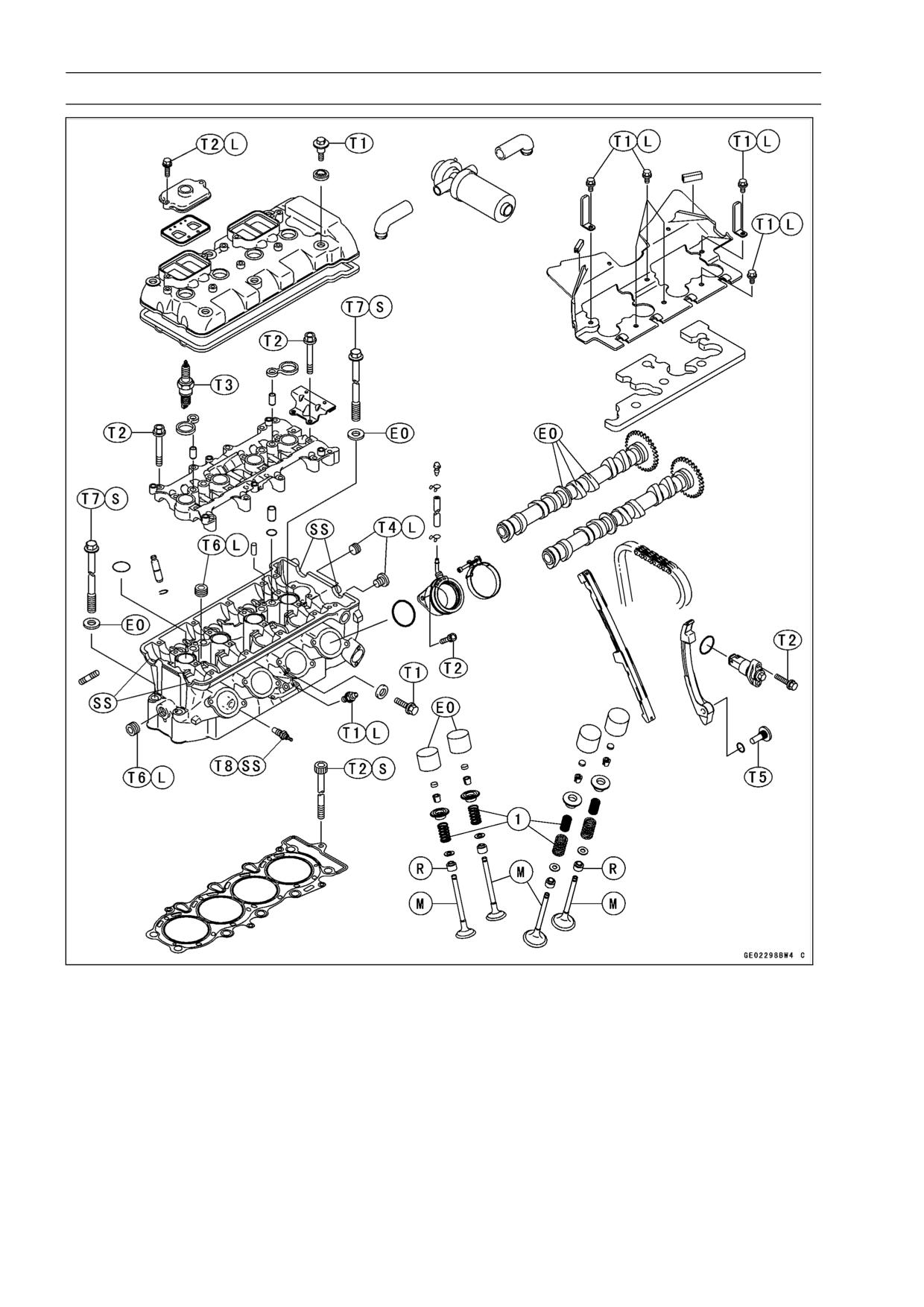
4-2 ENGINE TOP END
Exploded View
1. Closed coil end faces downward.
T8: 7.8 N·m (0.80 kgf·m, 69 in·lb)
T1: 9.8 N·m (1.0 kgf·m, 87 in·lb)
EO: Apply engine oil.
T2: 12 N·m (1.2 kgf·m, 104 in·lb)
L: Apply a non-permanent locking agent.
T3: 13 N·m (1.3 kgf·m, 113 in·lb)
M: Apply molybdenum disulfide grease.
T4: 15 N·m (1.5 kgf·m, 11 ft·lb)
R: Replacement Parts
T5: 25 N·m (2.5 kgf·m, 18 ft·lb)
S: Follow the specific tightening sequence.
T6: 20 N·m (2.0 kgf·m, 14.5 ft·lb)
SS: Apply silicone sealant.
T7: 49 N·m (5.0 kgf·m, 36 ft·lb)
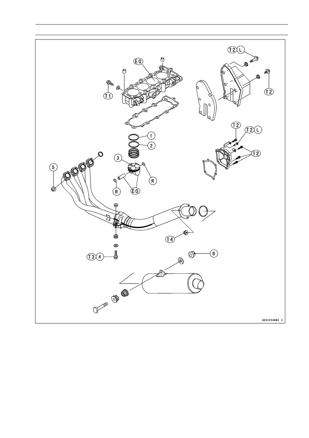
ENGINE TOP END 4-3
Exploded View
1. R marked side face up.
T2: 12 N·m (1.2 kgf·m, 104 in·lb)
2. RN marked side face up.
T3: 34 N·m (3.5 kgf·m, 25 ft·lb)
3. A marking hollow facing forward.
T4: 45 N·m (4.5 kgf·m, 33 ft·lb)
4. Exhaust Pipe Mounting Bolt
EO: Apply engine oil.
5. Exhaust Pipe Holder Nuts
L: Apply a non-permanent locking agent.
6. Muffler Mounting Nut
R: Replacement Parts
T1: 9.8 N·m (1.0 kgf·m, 87 in·lb)
4-4 ENGINE TOP END
Specifications
Item
Standard
Service Limit
Clean Air System
Vacuum Switch Valve Closing
Open → Close
Pressure
57 ∼ 65 kPa (430 ∼ 490 mmHg)
- - -
Camshafts
Cam Height:
Exhaust
34.345 ∼ 34.453 mm
34.24 mm (1.348 in.)
(1.352 ∼ 1.356 in.)
Inlet
35.146 ∼ 35.254 mm
35.04 mm (1.380 in.)
(1.384 ∼ 1.388 in.)
Camshaft Journal, Camshaft Cap
0.038 ∼ 0.081 mm
0.17 mm (0.0067 in.)
Clearance
(0.0015 ∼ 0.0032 in.)
Camshaft Journal Diameter
23.940 ∼ 23.962 mm
23.91 mm (0.941 in.)
(0.9425 ∼ 0.9434 in.)
Camshaft Bearing Inside Diameter
24.000 ∼ 24.021 mm
24.08 mm (0.948 in.)
(0.9449 ∼ 0.9457 in.)
Camshaft Runout
TIR 0.02 mm (0.0008 in.) or less
TIR 0.1 mm (0.004 in.)
Cylinder Head
Cylinder Compression
(usable range)
950 ∼ 1 450 kPa (9.7 ∼ 14.8
kgf/cm², 138 ∼ 210 psi) @350 r/min
- - -
(rpm)
Cylinder Head Warp
- --
0.05 mm (0.002 in.)
Valves
Valve Clearance:
0.22 ∼ 0.31 mm
Exhaust
- - -
(0.0087 ∼ 0.0122 in.)
0.11 ∼ 0.19 mm
Inlet
- - -
(0.0043 ∼ 0.0075 in.)
Valve Head Thickness:
Exhaust
1.0 mm (0.04 in.)
0.6 mm (0.024 in.)
Inlet
0.5 mm (0.02 in.)
0.25 mm (0.010 in.)
Valve Stem Bend
TIR 0.01mm (0.0004 in.) or less
TIR 0.05 mm (0.002 in.)
Valve Stem Diameter:
Exhaust
3.955 ∼ 3.970 mm
3.94 mm (0.155 in.)
(0.1557 ∼ 0.1563 in.)
Inlet
3.975 ∼ 3.990 mm
3.96 mm (0.156 in.)
(0.1565 ∼ 0.1571 in.)
Valve Guide Inside Diameter
Exhaust
4.000 ∼ 4.012 mm
4.08 mm (0.161 in.)
(0.1575 ∼ 0.1580 in.)
Inlet
4.000 ∼ 4.012 mm
4.08 mm (0.161 in.)
(0.1575 ∼ 0.1580 in.)
Valve/Valve Guide Clearance
(Wobble Method):
Exhaust
0.10 ∼ 0.18 mm
0.35 mm (0.014 in.)
(0.004 ∼ 0.007 in.)
ENGINE TOP END 4-5
Specifications
Item
Standard
Service Limit
Inlet
0.03 ∼ 0.12 mm
0.29 mm (0.011 in.)
(0.0012 ∼ 0.0047 in.)
Valve Seat Cutting Angle
45°, 32°, 60°
- - -
Valve Seat Surface:
Width:
Exhaust
0.5 ∼ 1.0 mm (0.02 ∼
0.04 in.)
- - -
Inlet
0.5 ∼ 1.0 mm (0.02 ∼
0.04 in.)
- - -
Outside Diameter:
Exhaust
22.1 ∼ 22.3 mm
- - -
(0.870 ∼ 0.878 in.)
Inlet
26.4 ∼ 26.6 mm
- - -
(1.039 ∼ 1.047 in.)
Valve Spring Free Length:
Exhaust (Inner)
49.0 mm (1.93 in.)
47.6 mm (1.87 in.)
Inlet (Inner)
44.1 mm (1.44 in.)
42.6 mm (1.68 in.)
Inlet (Outer)
48.2 mm (1.90 in.)
46.6 mm (1.83 in.)
Cylinder, Piston
Cylinder Inside Diameter
65.960 ∼ 65.972 mm
66.06 mm (2.601 in.)
(2.5968 ∼ 2.5973 in.)
Piston Diameter
65.935 ∼ 65.950 mm
65.78 mm (2.590 in.)
(2.5957 ∼ 2.5965 in.)
Piston/Cylinder Clearance:
0.010 ∼ 0.037 mm
- - -
(0.0004 ∼ 0.0015 in.)
Piston Ring/Groove Clearance
Top
0.05 ∼ 0.09 mm
0.19 mm (0.0075 in.)
(0.0020 ∼ 0.0035 in.)
Second
0.03 ∼ 0.07 mm
0.17 mm (0.0067 in.)
(0.0012 ∼ 0.0028 in.)
Piston Ring Groove Width:
Top
0.84 ∼ 0.86 mm
0.94 mm (0.037 in.)
(0.0331 ∼ 0.0339 in.)
Second
0.82 ∼ 0.84 mm
0.92 mm (0.036 in.)
(0.0323 ∼ 0.0331 in.)
Piston Ring Thickness:
Top
0.77 ∼ 0.79 mm
0.70 mm (0.028 in.)
(0.0303 ∼ 0.0311 in.)
Second
0.77 ∼ 0.79 mm
0.70 mm (0.028 in.)
(0.0303 ∼ 0.0311 in.)
Piston Ring End Gap:
Top
0.15 ∼ 0.30 mm
0.6 mm (0.024 in.)
(0.0059 ∼ 0.0118 in.)
Second
0.30 ∼ 0.45 mm
0.8 mm (0.031 in.)
(0.0118 ∼ 0.0177 in.)
4-6 ENGINE TOP END
Specifications
Special Tools - Compression Gauge, 20 kgf/cm²: 57001-221
Valve Spring Compressor Assembly: 57001-241
Piston Pin Puller Assembly: 57001-910
Valve Seat Cutter, 45° -
27.5: 57001-1114
Valve Seat Cutter, 45° -
32: 57001-1115
Valve Seat Cutter, 32° -
28: 57001-1119
Valve Seat Cutter, 32° -
30: 57001-1120
Valve Seat Cutter, 60° -
30: 57001-1123
Valve Seat Cutter Holder Bar: 57001-1128
Valve Spring Compressor Adapter,
20: 57001-1154
Valve Spring Compressor Adapter,
22: 57001-1202
Spark Plug Wrench, Hex 16: 57001-1262
Valve Guide Arbor,
4: 57001-1273
Valve Guide Reamer,
4: 57001-1274
Valve Seat Cutter Holder,
4: 57001-1275
Fork Oil Level Gauge: 57001-1290
Compression Gauge Adapter, M10 × 1.0: 57001-1317
Valve Seat Cutter, 60° -
33: 57001-1334
Sealant - Kawasaki Bond (Silicone Sealant): 56019-120
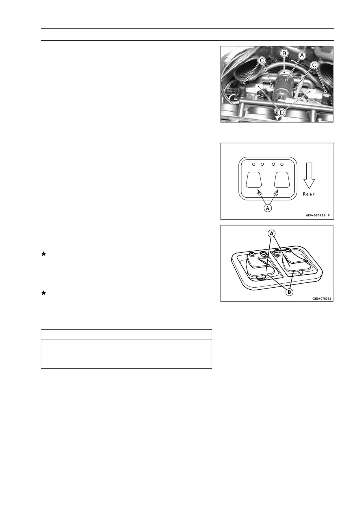
ENGINE TOP END 4-7
Clean Air System
Air Suction Valve Removal
Remove:
•
Seats (see Frame chapter)
Fuel Tank, Air Cleaner Housing (see Fuel System chap-
ter)
Separate the intake silencer [A] from the vacuum switch
•
valve [B].
Remove:
•
Vacuum Switch Valve with the Hoses
Air Suction Valve Cover Bolts [C]
Air Suction Valve Cover [D]
Air Suction Valve
Air Suction Valve Installation
Install the air suction valve so that its wider side [A] of the
•
reed faces the rear.
Apply a non-permanent locking agent to the threads of
•
the air suction valve cover bolts, and tighten them with
the specified torque.
Torque - Air Suction Valve Cover Bolts: 12 N·m (1.2 kgf·m,
104 in·lb)
Air Suction Valve Inspection
Visually inspect the reeds [A] for cracks, folds, warps,
•
heat damage, or other damage.
If there is any doubt as to the condition of the reed, replace
the air suction valve as an assembly.
Check the reed contact areas [B] of the valve holder for
•
grooves, scratches, any signs of separation from the
holder, or heat damage.
If there is any doubt as to the condition of the reed contact
areas, replace the air suction valve as an assembly.
If any carbon or other foreign particles have accumulated
•
between the reed and the reed contact area, wash the
valve assembly with a high flash-point solvent.
CAUTION
Do not scrape off the deposits with a scraper as this
could damage the rubber, requiring replacement of
the suction valve assembly.
Vacuum Switch Valve Removal
Remove the vacuum switch valve (see Air Suction Valve
•
Removal).
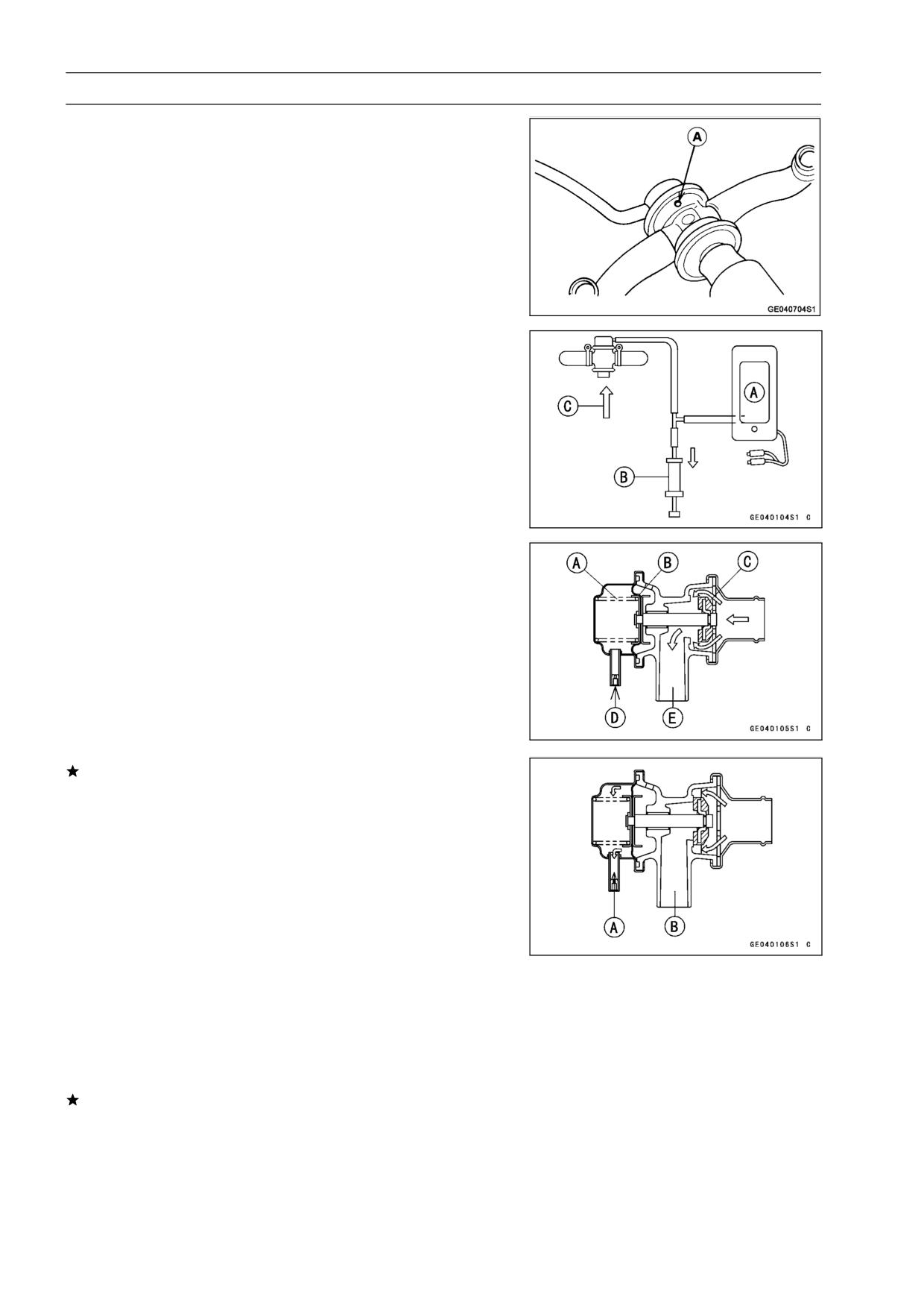
4-8 ENGINE TOP END
Clean Air System
Vacuum Switch Valve Installation
Install the vacuum switch valve so that the air hole [A]
•
faces downwards.
Route the hoses correctly (see General Information chap-
•
ter).
Vacuum Switch Valve Test
Remove:
•
Fuel Tank, Air Cleaner Housing (see Fuel System chap-
ter)
Vacuum Switch Valve
Connect a vacuum gauge [A] and syringe [B] or fork oil
•
level gauge to the vacuum hoses as shown.
Special Tool - Fork Oil Level Gauge: 57001-1290
Air Flow [C]
Gradually raise the vacuum (lower the pressure) applied
•
to the vacuum switch valve, and check the valve opera-
tion. When the vacuum is low, the vacuum switch valve
should permit air to flow. When the vacuum raises to
valve closing pressure, it should stop air flow.
Spring [A]
Diaphragm [B]
Valve [C]
Low Vacuum [D]
Secondary Air Flow [E]
If the vacuum switch valve does not operate as described,
replace it with a new one.
NOTE
○To check air flow through the vacuum switch valve, just
blow through the air cleaner hose.
Vacuum Switch Valve Closing Pressure (Open → Close)
Standard:
57 ∼ 65 kPa (430 ∼ 490 mmHg)
High Vacuum [A]
Secondary air cannot flow [B]
Clean Air System Hose Inspection
Be certain that all the hoses are routed without being flat-
•
tened or kinked, and are connected correctly to the air
cleaner housing, vacuum switch valve, #1 and #4 carbu-
retor holders and air suction valve covers.
If they are not, correct them. Replace them if they are
damaged.
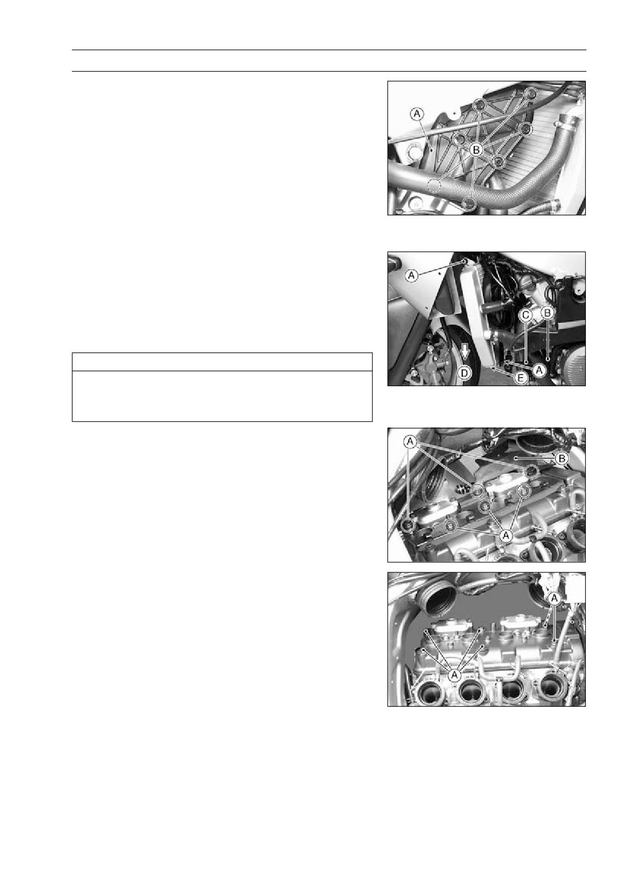
ENGINE TOP END 4-9
Cylinder Head Cover
Cylinder Head Cover Removal
Remove:
•
Lower Fairing (see Frame chapter)
Coolant (drain, see Cooling System chapter) Other than
US, CAL Models
Seats (see Frame chapter)
Fuel Tank, Air Cleaner Housing and Carburetor (see
Fuel System chapter)
Vacuum Valve (California Model only)
Vacuum Switch Valve and Hoses
Stick Coil (see Electrical System)
Engine Side Cover [A] and Bolts [B]
Turn the handlebar to left side.
•
Remove:
•
Radiator Mount Bolts [A]
Radiator Bracket Bolts [B]
Radiator Bracket [C]
Move the radiator toward the down [D] and put the suit-
•
able support [E] under the radiator.
CAUTION
Do not touch the radiator core. This could damage
the radiator fins, resulting in loss of cooling effi-
ciency.
Remove:
•
Baffle Plate Bolts [A]
Baffle Plate [B]
NOTE
○If the baffle plate cannot easily be removed, remove the
air suction valve covers.
Remove the cylinder head cover bolts [A].
•
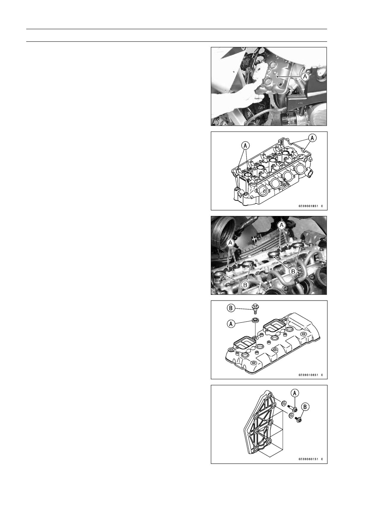
4-10 ENGINE TOP END
Cylinder Head Cover
Remove the cylinder head cover [A].
•
Cylinder Head Cover Installation
Replace the head cover gasket with a new one if dam-
•
aged.
Apply silicone sealant to the cylinder head as shown [A].
•
Sealant - Kawasaki Bond (Silicone Sealant): 56019-120
Be sure to install the pins [A] and rubber gaskets [B].
•
Install the washer with the metal side [A] faces upward.
•
Tighten:
•
Torque - Cylinder Head Cover Bolts: 9.8 N·m (1.0 kgf·m, 87
in·lb) [B]
Baffle Plate Bolts: 9.8 N·m (1.0 kgf·m, 87 in·lb)
Apply a non-permanent locking agent to the threads of
•
the engine side cover bolt [A].
Tighten:
•
Torque - Engine Side Cover Bolts: 12 N·m (1.2 kgf·m, 104
in·lb) [A] [B]
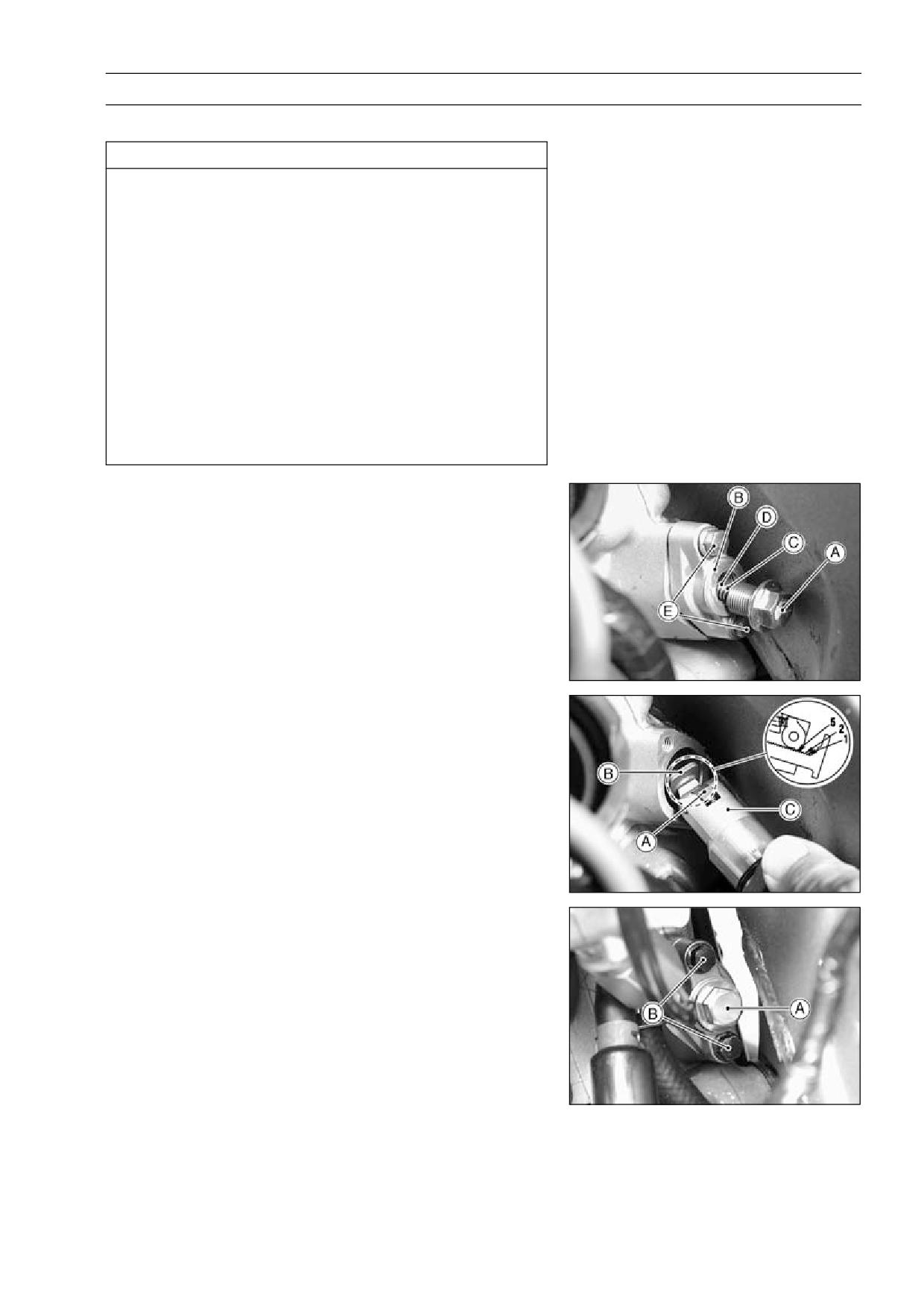
ENGINE TOP END 4-11
Camshaft Chain Tensioner
Camshaft Chain Tensioner Removal
CAUTION
This is a non-return type camshaft chain tensioner.
The push rod does not return to its original position
once it moves out to take up camshaft chain slack.
Observe all the rules listed below:
When removing the tensioner, do not take out the
mounting bolts only halfway. Retightening the
mounting bolts from this position could damage
the tensioner and the camshaft chain. Once the
bolts are loosened, the tensioner must be removed
and reset as described in "Camshaft Chain Ten-
sioner Installation."
Do not turn over the crankshaft while the tensioner
is removed. This could upset the camshaft chain
timing, and damage the valves.
Remove:
•
Seats (see Frame chapter)
Fuel Tank (see Fuel System chapter)
Cap Bolt [A]
Washer [B]
Spring [C]
Rod [D]
Remove the mounting bolts [E] and take off the camshaft
•
chain tensioner.
Camshaft Chain Tensioner Installation
Release the stopper [A] and push the push rod [B] into
•
the tensioner body [C].
○Insert the push rod so that the push rod teeth are leaved
five notches.
Install the tensioner body so that the stopper faces up-
•
ward.
Tighten:
•
Torque - Camshaft Chain Tensioner Mounting Bolts [B]: 12
N·m (1.2 kgf·m, 104 in·lb)
Install the spring and washer.
•
Tighten the cap bolt [A].
•
Turn the crankshaft 2 turns clockwise to allow the ten-
•
sioner to expand and recheck the camshaft chain timing.
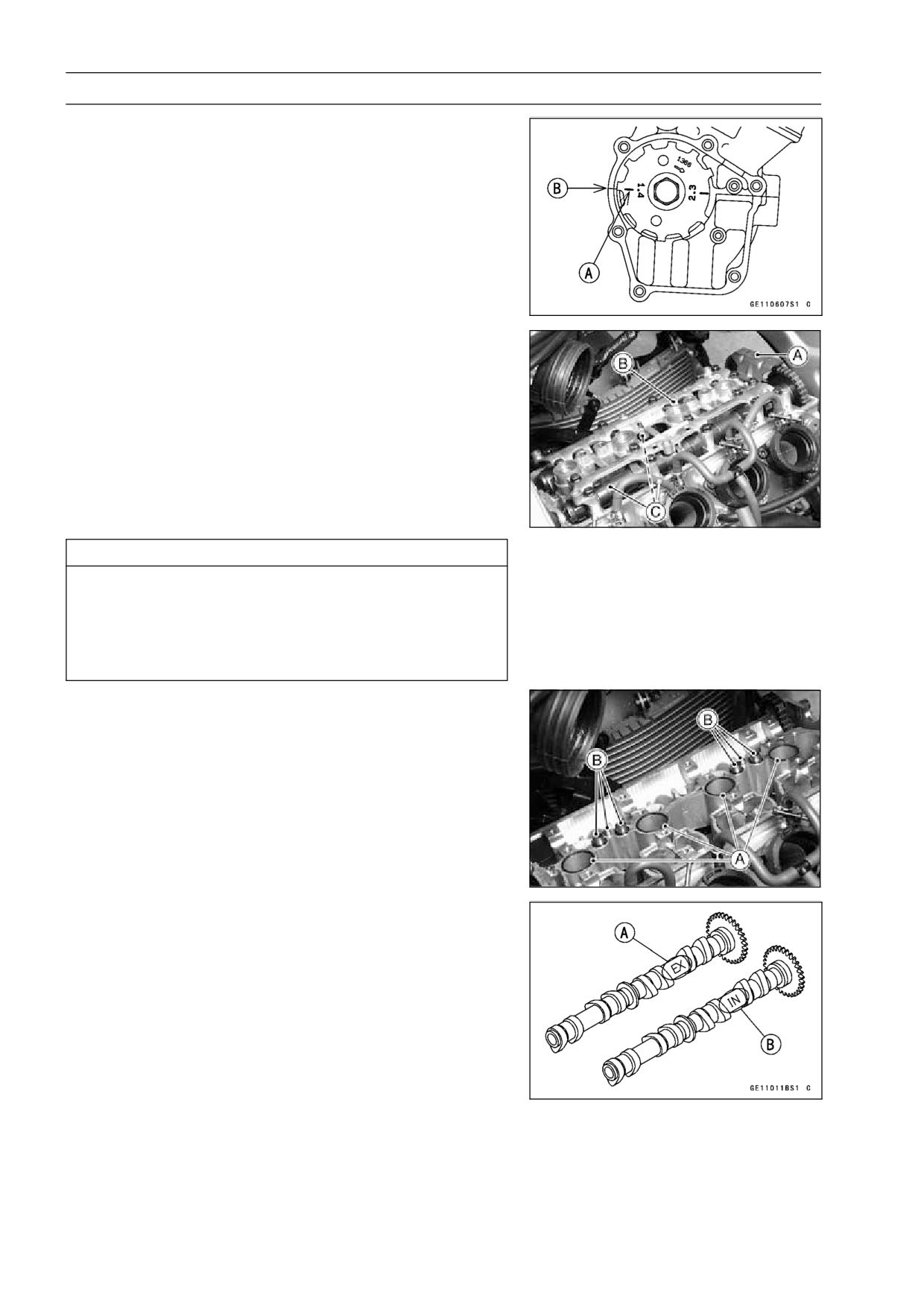
4-12 ENGINE TOP END
Camshaft, Camshaft Chain
Camshaft Removal
Remove:
•
Cylinder Head Cover (see Cylinder Head Cover Re-
moval)
Pickup Coil Cover
Position the crankshaft at #1, 4 piston TDC.
•
[A] TDC mark for #1, 4 Pistons
[B] Timing Mark (crankcase halves mating surface)
Remove:
•
Camshaft Chain Tensioner (see Camshaft Chain Ten-
sioner Removal)
Rubber Gaskets and Cylinder Head Cover Gasket
Camshaft Cap Bolts
Chain Guide [A]
Camshaft Cap [B]
Camshafts [C]
Stuff a clean cloth into the chain tunnel to keep any parts
•
from dropping into the crankcase.
CAUTION
The crankshaft may be turned while the camshafts
are removed. Always pull the chain taut while turn-
ing the crankshaft. This avoids kinking the chain
on the lower (crankshaft) sprocket. A kinked chain
could damage both the chain and the sprocket.
Camshaft Installation
Be sure to install the following parts.
•
[A] O-rings
[B] Pins
Apply engine oil to all cam parts and journals.
•
If a new camshaft is to be used, apply a thin coat of molyb-
•
denum disulfide grease to the cam surfaces.
NOTE
○The exhaust camshaft has a 117 EX mark [A] and the
inlet camshaft has a 117 IN mark [B]. Be careful not to
mix up these shafts.
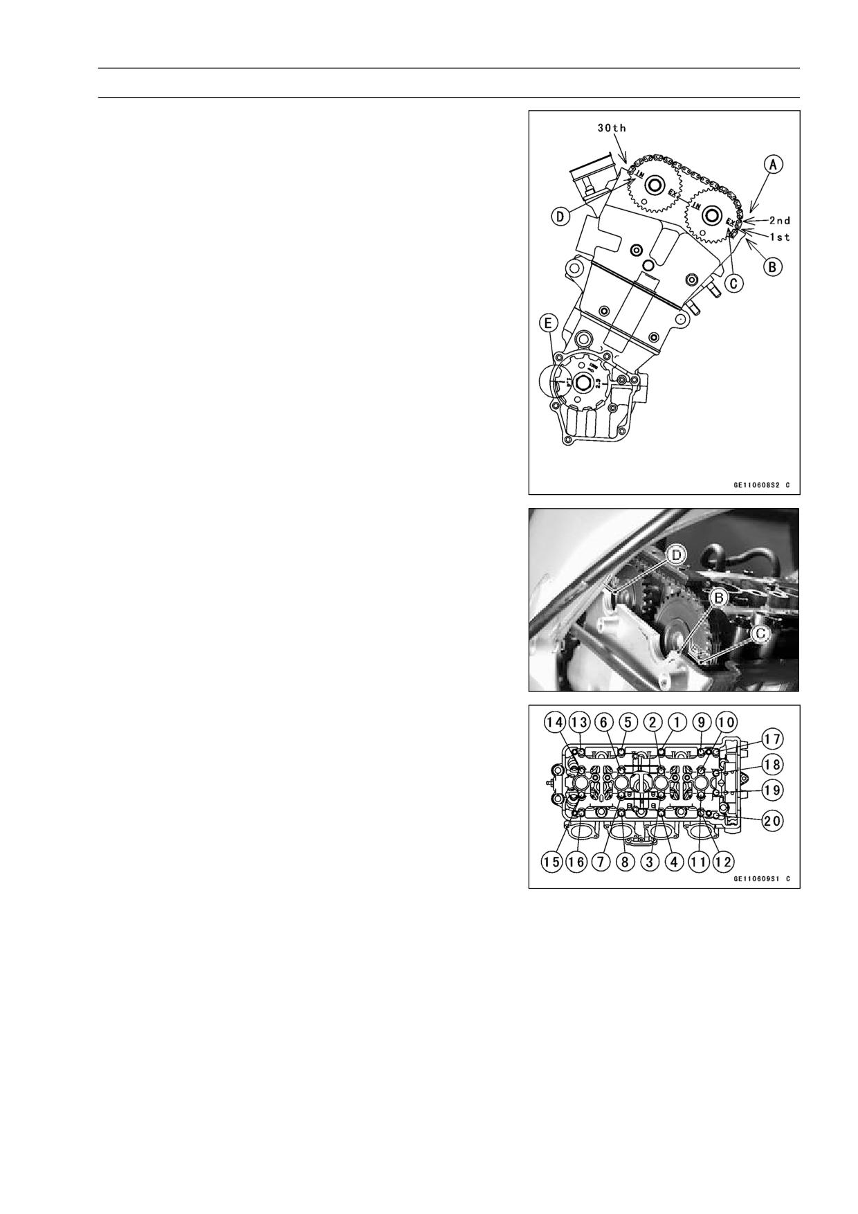
ENGINE TOP END 4-13
Camshaft, Camshaft Chain
Position the crankshaft at #1, 4 piston TDC.
•
Pull the tension side (exhaust side) [A] of the chain taut
•
to install the chain.
Engage the camshaft chain with the camshaft sprockets
•
so that the timing marks on the sprockets are positioned
as shown.
○The timing marks of #1, 4 must be aligned with the lower
surface of crankcase of rear side [E].
○The timing marks must be aligned with the cylinder head
upper surface [B].
[C] EX mark
[D] IN mark
Install the camshaft cap and chain guide.
•
○First tighten the camshaft cap and all chain guide bolts
evenly to seat the camshaft in place, then tighten all bolts
following the specified tightening sequence.
Torque - Camshaft Cap Bolts: 12 N·m (1.2 kgf·m, 104 in·lb)
Camshaft Chain Guide Bolts: 12 N·m (1.2 kgf·m,
104 in·lb)
Tighten the camshaft chain tensioner (see Camshaft
•
Chain Tensioner Installation).
Install the cylinder head cover (see Cylinder Head Cover
•
Installation).
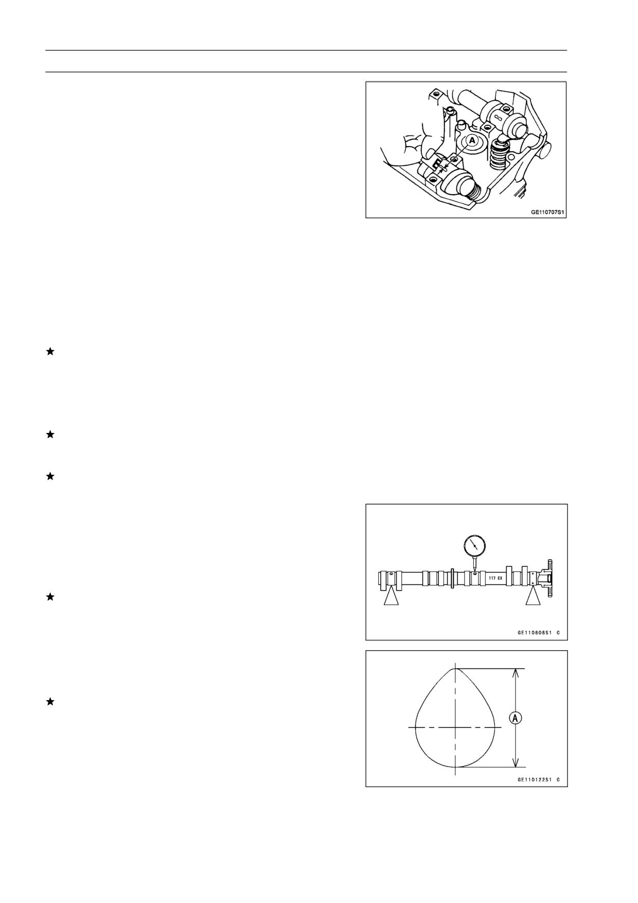
4-14 ENGINE TOP END
Camshaft, Camshaft Chain
Camshaft, Camshaft Cap Wear Inspection
Cut strips of plastigage to journal width. Place a strip
•
on each journal parallel to the camshaft installed in the
correct position.
Measure each clearance between the camshaft journal
•
and the camshaft cap using plastigage (press gauge) [A].
Tighten:
•
Torque - Camshaft Cap Bolts: 12 N·m (1.2 kgf·m, 104 in·lb)
Camshaft Chain Guide Bolts: 12 N·m (1.2 kgf·m,
104 in·lb)
NOTE
○Do not turn the camshaft when the plastigage is be-
tween the journal and camshaft cap.
Camshaft Journal, Camshaft Cap Clearance
Standard:
0.038 ∼ 0.081 mm (0.0015 ∼ 0.0032 in.)
Service Limit:
0.17 mm (0.0067in.)
If any clearance exceeds the service limit, measure the
diameter of each camshaft journal with a micrometer.
Camshaft Journal Diameter
Standard:
23.940 ∼ 23.962 mm (0.9425 ∼ 0.9434 in.)
Service Limit:
23.91 mm (0.941 in.)
If the camshaft journal diameter is less than the service
limit, replace the camshaft with a new one and measure
the clearance again.
If the clearance still remains out of the limit, replace the
cylinder head unit.
Camshaft Runout Inspection
Remove the camshaft.
•
Set the camshaft in a camshaft alignment jig or on V
•
blocks.
Measure runout with a dial gauge at the specified place
•
as shown.
If the runout exceeds the service limit, replace the shaft.
Camshaft Runout
Standard: TIR 0.1 mm (0.004 in.)
Cam Wear Inspection
Remove the camshaft.
•
Measure the height [A] of each cam with a micrometer.
•
If the cams are worn down past the service limit, replace
the camshaft.
Cam Height
Standard:
Exhaust
34.345 ∼ 34.453 mm (1.352 ∼ 1.356 in.)
Inlet
35.146 ∼ 35.254 mm (1.384 ∼ 1.388 in.)
Service Limit:
Exhaust
34.24 mm (1.348 in.)
Inlet
35.04 mm (1.380 in.)
//////////////////////////////////////////