Kawasaki Ninja ZX-12R Motorcycle. Service Manual (2002-2005 year) - page 15
 

  Index      Manuals     Kawasaki Ninja ZX-12R Motorcycle. Service Manual (2002-2005 year)


Search            copyright infringement  


Content      ..     13      14      15      16     ..


Kawasaki Ninja ZX-12R Motorcycle. Service Manual (2002-2005 year) - page 15


14-2 STEERING

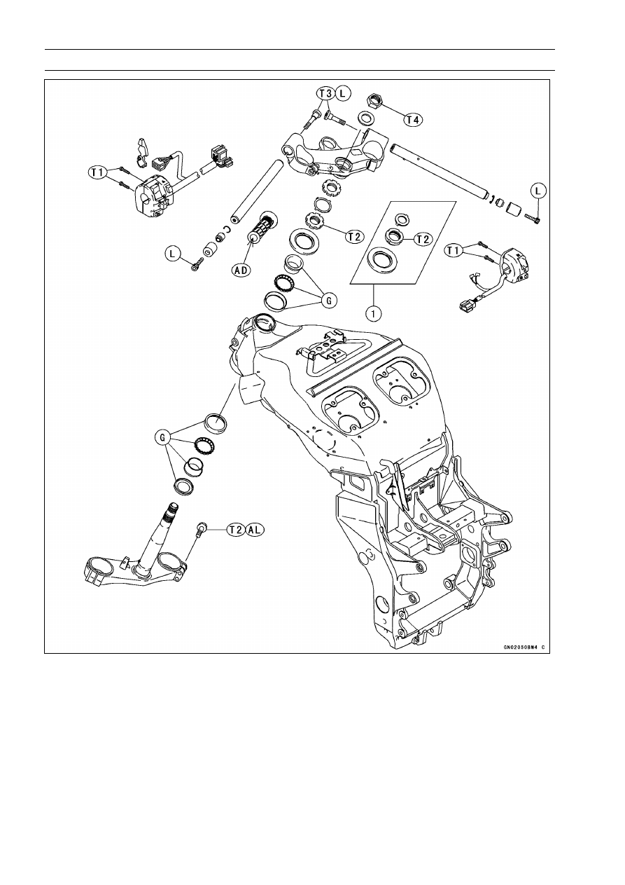
Exploded View

1. ZX1200-B1/B2

T1: 3.5 N·m (0.36 kgf·m, 31 in·lb)
T2: 20 N·m (2.0 kgf·m, 15 ft·lb)
T3: 34 N·m (3.5 kgf·m, 25 ft·lb)
T4: 54 N·m (5.5 kgf·m, 40 ft·lb) (ZX1200-B1/B2)

78 N·m (8.0 kgf·m, 57 ft·lb) (ZX1200-B3

)

AD: Apply adhesive.

AL: Tighten the two clamp bolts alternately two times to ensure even tightening torque.

G: Apply grease.

L: Apply a non-permanent locking agent.

STEERING 14-3

Specifications

Special Tools - Head Pipe Outer Race Press Shaft: 57001-1075

Steering Stem Nut Wrench: 57001-1100
Head Pipe Outer Race Remover ID > 37 mm: 57001-1107
Jack: 57001-1238
Steering Stem Bearing Driver, 42.5: 57001-1344
Steering Stem Bearing Driver Adapter, 41.5: 57001-1345
Head Pipe Outer Race Driver, 55: 57001-1446
Head Pipe Outer Race Driver, 47: 57001-1447

14-4 STEERING

Steering

Steering Inspection

Refer to the Steering Inspection in the Periodic Mainte-
nance chapter.

Steering Adjustment

Refer to the Steering Inspection in the Periodic Mainte-
nance chapter.

STEERING 14-5

Steering Stem

Stem, Stem Bearing Removal

Remove:

Brake Hose Joint Cover Screws [A]
Front Wheel (see Wheels/Tires chapter)
Front Fork (see Suspension chapter)
Steering Stem Head Nut and Washer
Steering Stem Head with Handlebars

Remove the brake hose joint bolt [A].

ZX1200-B1/B2

Take off the lock washer [A] to remove the steering stem
nut [B] and pull the steering stem [C] with the bearing and
oil seal downward.

Special Tool - Steering Stem Nut Wrench: 57001-1100

Remove the oil seal, bearing inner race and ball bearing
assy from the upper head pipe.

ZX1200-B3

Straighten the claw washer tabs [A].

Remove the steering stem locknut [B].

Special Tool - Steering Stem Nut Wrench: 57001-1100

Remove the claw washer [A].

14-6 STEERING

Steering Stem

Pushing up the stem base, and remove the steering stem
nut [A] with oil seal.

Special Tool - Steering Stem Nut Wrench [B]: 57001-1100

Remove:

Steering Stem [C]
Upper Ball Bearing Inner Race

Drive out the bearing outer races [B] from the head pipe.

Special Tool - Head Pipe Outer Race Remover ID > 37 mm:

57001-1107 [A]

NOTE

If either steering stem bearing is damaged, it is recom-
mended that both the upper and lower bearings (includ-
ing outer races) should be replaced with new ones.

Remove the lower inner race [A] (with its grease seal [B])
which is pressed onto the steering stem with a suitable
commercially available bearing puller or chisel [C].

Stem, Stem Bearing Installation

Replace the outer races, inner races and ball bearings
with new ones.

Apply grease to the outer races, and drive them into the
head pipe at the same time.

Special Tools - Head Pipe Outer Race Press Shaft: 57001

-1075 [A]

Head Pipe Outer Race Driver,

55: 57001

-1446

Head Pipe Outer Race Driver,

47: 57001

-1447 [B]

STEERING 14-7

Steering Stem

Install the oil seal [A] on the steering stem, and drive the
lower ball bearing inner race [B] applied the grease on to
the stem.

Special Tools - Steering Stem Bearing Driver, 42.5: 57001

-1344 [C]

Steering Stem Bearing Driver Adapter,

41.5: 57001-1345 [D]

Install the lower ball bearing [A] onto the stem.

Apply grease to the lower and upper ball bearings [B] and
outer races.

Install the stem [A] through the head pipe and install the
ball bearing [B] and inner race [C] on it.

Install the oil seal [D] and steering stem nut [E].

Settle the inner races in place as follows:

Tighten the steering stem nut with 20 N·m (2.0 kgf·m, 15
ft·lb) of torque first, and loosen it a fraction of a turn until
it turns lightly. Afterward tighten it again with specified
torque using the stem nut wrench [A].

Check that there is no play and the steering stem turns
smoothly without rattles. If not, the bearings on the inner
races may be damaged.

Special Tool - Steering Stem Nut Wrench: 57001-1100

Torque - Steering Stem Nut: 20 N·m (2.0 kgf·m, 15 ft·lb)

14-8 STEERING

Steering Stem

ZX1200-B1/B2

Install the lock washer.

Install the stem head.

Install the washer, and tighten the stem head nut with
specified torque.

Install the front fork (see Suspension chapter).

NOTE

Tighten the fork upper clamp bolts first, next the stem
head nut, last the fork lower clamp bolts.

Tighten the two clamp bolts alternately two times to en-
sure even tightening torque.

Torque - Steering Stem Head Nut: 54 N·m (5.5 kgf·m, 40

ft·lb)

Front Fork Clamp Bolts (Upper):

20 N·m (2.0 kgf·m, 15 ft·lb)

Front Fork Clamp Bolts (Lower):

20 N·m (2.0 kgf·m, 15 ft·lb)

WARNING

Do not impede the handlebar turning by routing the
cables, harnesses and hoses improperly (see Gen-
eral Information chapter).

Install the removed parts (see appropriate chapters).

ZX1200-B3

Install the claw washer [A] so that its bent side [B] faces
upward, and engage the bent claws with the grooves of
stem locknut [C].

Hand tighten the stem locknut until it touches the claw
washer.

Tighten the stem locknut clockwise until the claws are
aligned with the grooves of stem nut [D], and bend the
2 claws downward [E].

Install the stem head.

Install the washer, and tighten the stem head nut with
specified torque.

Install the front fork (see Suspension chapter).

STEERING 14-9

Steering Stem

NOTE

Tighten the fork upper clamp bolts first, next the stem
head nut, last the fork lower clamp bolts.

Tighten the two clamp bolts alternately two times to en-
sure even tightening torque.

Torque - Steering Stem Head Nut: 78 N·m (8.0 kgf·m, 57

ft·lb)

Front Fork Clamp Bolts (Upper):

20 N·m (2.0 kgf·m, 15 ft·lb)

Front Fork Clamp Bolts (Lower):

20 N·m (2.0 kgf·m, 15 ft·lb)

WARNING

Do not impede the handlebar turning by routing the
cables, harnesses and hoses improperly (see Gen-
eral Information chapter).

Install the removed parts (see appropriate chapters).

Steering Bearing Lubrication and Inspection

Refer to the Steering Stem Bearing Lubrication in the Pe-
riodic Maintenance chapter.

Steering Stem Warp

Whenever the steering stem is removed, or if the steering
cannot be adjusted for smooth action, check the steering
stem for straightness [A].
If the steering stem shaft is bent, replace the steering
stem.

14-10 STEERING

Handlebar

Handlebar Removal

Remove:

Clutch Lever Assembly [A]
Left Handlebar Switch Housing [B]
Front Brake Master Cylinder [C]
Right Handlebar Switch Housing [D]
Throttle Case [E]

Remove:

Weight Bolts [A]
Handlebar Weight [B]
Fitting [C]
Clip [D]

Remove:

Throttle Grip
Handlebar Bolts [A]

Pull out the handlebars [B].

Handlebar Installation

Apply a non-permanent locking agent to the threads of
the handlebar bolts and weight bolts.

Torque - Handlebar Bolts: 34 N·m (3.5 kgf·m, 25 ft·lb)

Install the brake master cylinder (see Brakes chapter).

Install the clutch lever [A] so that the mating surface [B]
of the left handlebar switch housing is aligned with the
mating surface [C] of the clutch lever clamp.

Torque - Clutch Lever Clamp Bolts: 7.8 N·m (0.80 kgf·m, 69

in·lb)

Handlebar Switch Housing Screws: 3.5 N·m (0.36

kgf·m, 31 in·lb)

Install the removed parts (see appropriate chapters).

FRAME 15-1

15

Frame

Table of Contents

Exploded View...................................

15-2

Seats .................................................

15-5

Rear Seat Removal......................

15-5

Rear Seat Installation...................

15-5

Rear Seat Cover Removal ...........

15-5

Rear Seat Cover Installation ........

15-6

Front Seat Removal .....................

15-6

Front Seat Installation ..................

15-6

Seat Cover.........................................

15-7

Seat Cover Removal....................

15-7

Seat Cover Installation.................

15-7

Fairings..............................................

15-8

Lower Fairings (Left and Right)

Removal ....................................

15-8

Lower Fairings (Left and Right)

Installation .................................

15-8

Lower Inner Fairing Removal.......

15-9

Lower Inner Fairing Installation....

15-9

Upper Inner Fairings (Left and

Right) Removal .........................

15-9

Upper Inner Fairings (Left and

Right) Installation ......................

15-9

Wind Shield Removal...................

15-10

Wind Shield Installation................

15-10

Upper Inner Covers (Left and

Right) Removal .........................

15-10

Upper Inner Covers (Left and

Right) Installation ......................

15-10

Lower Inner Covers (Left and

Right) Removal .........................

15-10

Lower Inner Covers (Left and

Right) Installation ......................

15-11

Upper Fairing Removal ................

15-11

Upper Fairing Disassembly..........

15-12

Upper Fairing Assembly...............

15-13

Hot Wind Cover Installation .........

15-14

Fenders .............................................

15-15

Front Fender Removal .................

15-15

Front Fender Installation ..............

15-15

Rear Fender Rear Removal.........

15-15

Rear Fender Rear Installation......

15-15

Rear Fender Front Removal ........

15-16

Rear Fender Front Installation .....

15-16

Rear Frame .......................................

15-17

Rear Frame Removal...................

15-17

Rear Frame Installation................

15-17

Frame Inspection .........................

15-17

Storage Box.......................................

15-18

Storage Box Removal ..................

15-18

Storage Box Installation ...............

15-18

Side Stand .........................................

15-19

Side Stand Removal ....................

15-19

Side Stand Installation .................

15-19

15-2 FRAME

Exploded View

T1: 25 N·m (2.5 kgf·m, 18 ft·lb)
T2: 34 N·m (3.5 kgf·m, 25 ft·lb)
T3: 49 N·m (5.0 kgf·m, 36 ft·lb)
T4: 8.8 N·m (0.90 kgf·m, 78 in·lb)
T5: 44 N·m (4.5 kgf·m, 32 ft·lb)

G: Apply grease.

L: Apply a non-permanent locking agent.

FRAME 15-3

Exploded View

1. Key
2. Key Option

T1: 0.40 N·m (0.040 kgf·m, 3.5 in·lb)

15-4 FRAME

Exploded View

CA: Canadian Model
US: U.S.A. Model

FRAME 15-5

Seats

Rear Seat Removal

Insert the ignition switch key into the seat lock [A], turning
the key clockwise, pulling up on the rear of the seat with
seat cover [B], and pulling the seat backward.

Rear Seat Installation

Slip the rear seat hooks [A] into the hollow-cubic brackets
[B] on the frame.

Insert the seat projection [C] into the latch hole [D].

Push down the rear part of the seat until the lock clicks.

Rear Seat Cover Removal

Remove:

Rear Seat
Screws [A]

Remove the front bracket portions [A] from the projection
[B] of the seat.

Clear the bracket portions [A] from the seat band [B].

Pull the seat cover [C] out.

15-6 FRAME

Seats

Rear Seat Cover Installation

Fit the two projections [A] of the rear seat front portion into
the slots [B] in the front bracket of the seat cover.

Tighten the two screws.

Front Seat Removal

Remove:

Rear Seat (see Rear Seat Removal)
Mounting Bolts [A]

Remove the front seat [B] by pulling it up on the rear and
to the rear.

Front Seat Installation

Slip in the front seat holes [A] to the projections [B] on the
fuel tank.

Tighten the bolts with collar.

FRAME 15-7

Seat Cover

Seat Cover Removal

Remove:

Unscrew and pull out the rivet screws.

Seats
Rivet Screws [A] (Left and Right)
Hook Bolts [B]

Pull the front portions [C] of the seat cover outside, and
then remove the seat cover backward.

Pull out the seat lock wire [C] from the bracket [B] to re-
move the seat lock wire end [A].

Remove:

Screws [A]
Seat Lock [B]

Seat Cover Installation

Installation is reverse of removal.

Put the projections [A] into the grommets [B] on the frame
brackets.

15-8 FRAME

Fairings

Lower Fairings (Left and Right) Removal

Remove:

Screws [A]
Rivet Screws [B]
Allen Bolts [C]

Remove the lower fairings from the upper and lower inner
fairings.

Pull the lower inner fairing [A] forward to clear its projec-
tions [B] from the grommets [C] on the lower fairings [D].

Pull out the lower fairings [A] to clear the its grommets [B]
from the projections [C] of the upper inner fairings [D].

Lower Fairings (Left and Right) Installation

Be sure to place in the hot wind cover (see Hot Wind
Cover Installation).

Fit the projection [A] on the upper inner fairings [B] into
the grommets [C] on the lower fairings [D].

Insert the projection of the lower inner fairing into the
grommets on the lower fairings.

First tighten the Allen bolts temporarily, and tighten all
screws lightly.

Tighten the Allen bolts and screws.

FRAME 15-9

Fairings

Lower Inner Fairing Removal

Remove:

Screws [A]

Remove:

Lower Inner Fairing [A]

Pull the upper projection of the lower inner fairing [A] for-
ward to remove the its projections [B] from the grommets
[C] on the lower fairings [D].

Lower Inner Fairing Installation

Lower inner fairings installation is the reversed of re-
moval.

Push the upper portion of the lower inner fairing backward
to insert the its projection into the grommets on the lower
fairings.

Upper Inner Fairings (Left and Right) Removal

Remove:

Screw [A]
Lower Inner Fairing (see Lower Inner Fairing Removal)
Horn Mounting Bolts

Remove the upper inner fairings [A] from the lower fairings
and ducts.

Pull out the upper inner fairings inward to clear its projec-
tions [B] from the grommets [C] on the lower fairings and
ducts.

Upper Inner Fairings (Left and Right) Installation

Fit the projections into the grommets on the lower fairings
and ducts.

Install the lower inner fairing and horn mounting bolts.

15-10 FRAME

Fairings

Wind Shield Removal

Remove:

Pull off the wind shield upward after removing the screws.

Screws [A]
Wind Shield [B]

Wind Shield Installation

Insert the tabus [A] of the shield in to the holes [B] of the
upper fairing.

Tighten the screws.

Torque - Wind Shield Mounting Screws: 0.40 N·m (0.040

kgf·m, 3.5 in·lb)

Upper Inner Covers (Left and Right) Removal

Remove:

Screws [A]
Rivet Screws [B]

Upper Inner Covers (Left and Right) Installation

Upper inner covers installation is the reversed of removal.

Fit the projections [A] of upper inner covers [B] into the
grommets [C] on the lower inner covers [D].

Lower Inner Covers (Left and Right) Removal

Remove:

Fuel Tank Cover (see Fuel System (DFI) chapter)
Upper Inner Covers (see Upper Inner Covers Removal)
Rivet Screws [A]
Screws [B]

Pull out the projections [C] of the inner covers [D] upward
from each grommets of the ducts.

FRAME 15-11

Fairings

Lower Inner Covers (Left and Right) Installation

Lower inner covers installation is the reverse of removal.

Insert the projections [A] of the lower inner covers into the
holes [B] on the ducts.

Upper Fairing Removal

Remove:

Upper and Lower Inner Covers (see Upper and Lower
Inner Covers Removal)
Wind Shield (see Wind Shield Removal)

Remove the mounting screws [A] of left and right fairings.

Loosen the left and right air inlet duct clamp screws [A].

Remove the nuts [A] and take off the left and right rear
view mirrors.

Remove the projections [A] on the left and right upper
inner fairings [B] from the grommets [C] on the left and
right lower fairings [D] pulling out the lower portion inward
of the upper inner fairings.

15-12 FRAME

Fairings

Pull the upper fairing assembly forward and disconnect
the headlight harness connector [A].

Upper Fairing Disassembly

Remove the upper inner fairings [B] with loosening the
screws [A].

Remove:

Front Turn Signal Connectors [A]
Headlight Connectors [B]
City Light Connector [C]
Headlight Harness Bracket [D]

Remove:

Headlight Mounting Bolts [A]
Headlight Mounting Screws [B]
Headlight Assembly [C]

Remove:

Screws [A]
City Light Assembly [B]

FRAME 15-13

Fairings

Remove the ducts [B] with the screws [A] taken off.

Take off the screw [A] to remove the air inlet [B].

Remove the screw [A] to take off the plate [B] and turn
signal light.

Upper Fairing Assembly

Upper fairing assembly is the reversed of disassembly.

Insert the projections [A] of the air inlet into the holes [B]
of the upper fairing.

15-14 FRAME

Fairings

Hot Wind Cover Installation

Install the hot wind cover [A] following the below.

Cooling Hose [B]
Clutch Cable [C]
Crankshaft Sensor Lead [J]

Put in the lower part of the cover between the ribs [G] on
the crankshaft sensor cover [H].

Insert the pin [D] through the cover hole [E] to the bracket
[F].

FRAME 15-15

Fenders

Front Fender Removal

Remove:

Brake Hose Clamps [A] (Left and Right)
Screws [B] (Front Part Screws with Washers)
Bolts [C]
Reflector [E] (for US and Canadian Models)

Remove the front fender [D].

Front Fender Installation

Install the front fender to the front fork.

Tighten the screws and bolts.

Install the brake hose clamps to the front fender holes.

Rear Fender Rear Removal

Remove:

Rear Seat with cover (see Rear Seat Removal)
Front Seat (see Front Seat Removal)
Seat Cover (see Seat Cover Removal)
Storage Box (see Storage Box Removal)

Set up the fuel tank (see Fuel System (DFI) chapter).

Remove:

Nuts and Screws [A]

Disconnect:

Rear Turn Signal Connectors [A] (Left and Right)
Tail/Brake Light Connector [B]

Hang:

Canister (Californian Model Only)
ECU (see Fuel System (DFI) chapter)

Remove:

Bolts [C]

Pull backward the rear fender rear with the rear turn signal
and reflector (for US and Canadian models).

Rear Fender Rear Installation

Install the front part of the rear fender rear under the rear
fender front.

15-16 FRAME

Fenders

Rear Fender Front Removal

Remove:

Rear Fender Rear (see Rear Fender Rear Removal)
Hose Clamps [A]
Separator [B]

Remove the rear fender front.

Move the rear fender front backward until it stops, and
then pull downward the right side of the rear fender front
[A] to clear the brackets [B].

Rear Fender Front Installation

Install the hose and harness clamps in accordance with
Hose, Harness Routing section in General Information
chapter.

Insert both side grooves [A] of the rear fender front into
the frame brackets [B].

FRAME 15-17

Rear Frame

Rear Frame Removal

Remove:

Seats (see Front and Rear Seats Removal)
Rear Fender Front (see Rear Fender Front Removal)
ECU (Not Disconnect, see Fuel System (DFI) chapter)

Disconnect:

Atmospheric Pressure Sensor Connector
Regulator/Rectifier Connectors
Muffler Mounting Bolt [A]
Fuel Tank Mount Bracket Bolts [B]
Rear Footpeg Holder Bolts [C]
Frame Bolts and Nuts [D]

Rear Frame Installation

Tighten the frame bolts and nuts,

Torque - Rear Frame Bolts and Nuts: 44 N·m (4.5 kgf·m, 32

ft·lb)

Rear Footpeg Holder Bolts: 34 N·m (3.5 kgf·m, 25

ft·lb)

Frame Inspection

Visually inspect the frame for cracks, dents, bending, or
warp.
If there is any damage to the frame, replace it.

WARNING

A repaired frame may fail in use, possibly causing
an accident. If the frame is bent, dented, cracked,
or warped, replace it.

15-18 FRAME

Storage Box

Storage Box Removal

Remove:

Seats (see this chapter)
Band [A]
Bolts [B]
Bolt [C]

Pulling up the rear part of the box backward.

Storage Box Installation

Insert the front part [A] of the box into the hook [B] of the
rear fender rear.

FRAME 15-19

Side Stand

Side Stand Removal

Raise the rear wheel off the ground with the stand.

Disconnect the side stand switch lead connectors.

Remove:

Side Stand Bolt [A]
Side Stand Bracket Bolts [B]
Spring [C]
Side Stand [D]
Side Stand Switch Bolt [E]

Side Stand Installation

Apply grease to the sliding area [B] of the side stand [A].

Tighten the bolt and lock them with the nut.

Torque - Side Stand Bolt: 44 N·m (4.5 kgf·m, 32 ft·lb)

Side Stand Bracket Bolts: 49 N·m (5.0 kgf·m, 36

ft·lb)

Hook the spring

Install the side stand switch.

Apply a non-permanent locking agent to the thread of the
switch bolt.

Torque - Side Stand Switch Bolt: 8.8 N·m (0.90 kgf·m, 78

in·lb)

ELECTRICAL SYSTEM 16-1

16

Electrical System

Table of Contents

Exploded View...................................

16-3

Specifications ....................................

16-8

Parts Location....................................

16-10

Precautions........................................

16-11

Electrical Wiring.................................

16-13

Wiring Inspection .........................

16-13

Battery ...............................................

16-14

Battery Removal ..........................

16-14

Battery Installation .......................

16-15

Electrolyte Filling..........................

16-16

Initial Charge................................

16-18

Precautions ..................................

16-18

Interchange ..................................

16-19

Charging Condition Inspection.....

16-19

Refreshing Charge.......................

16-19

Charging System ...............................

16-21

Alternator Cover Removal............

16-21

Alternator Cover Installation.........

16-21

Stator Coil Removal .....................

16-21

Stator Coil Installation ..................

16-22

Alternator Rotor Removal ............

16-22

Alternator Rotor Installation .........

16-23

Alternator Inspection ....................

16-24

Regulator/Rectifier Inspection......

16-25

Regulator/Rectifier Output

Voltage Inspection.....................

16-28

Ignition System ..................................

16-30

Crankshaft Sensor Removal ........

16-30

Crankshaft Sensor Installation .....

16-31

Crankshaft Sensor Inspection......

16-31

Crankshaft Sensor Peak Voltage

Inspection..................................

16-31

Camshaft Position Sensor

Removal ....................................

16-32

Camshaft Position Sensor

Installation .................................

16-32

Camshaft Position Sensor

Inspection..................................

16-33

Camshaft Position Sensor Peak

Voltage Inspection.....................

16-33

Stick Coil (Ignition Coil together

with Spark Plug Cap) Removal .

16-34

Stick Coil (Ignition Coil together

with Spark Plug Cap)
Installation .................................

16-34

Stick Coil (Ignition Coil together

with Spark Plug Cap) Inspection

16-34

Stick Coil Primary Peak Voltage

Inspection..................................

16-35

Spark Plug Removal ....................

16-35

Spark Plug Installation .................

16-36

Spark Plug Cleaning and

Inspection..................................

16-36

Spark Plug Gap Inspection ..........

16-36

Interlock Operation Inspection .....

16-36

IC Igniter Inspection .....................

16-37

Ignition System Inspection ...........

16-37

Electric Starter System ......................

16-41

Starter Motor Removal.................

16-41

Starter Motor Installation..............

16-41

Starter Motor Disassembly...........

16-42

Starter Motor Assembly ...............

16-42

Brush Inspection ..........................

16-43

Commutator Cleaning and

Inspection..................................

16-43

Armature Inspection.....................

16-44

Brush Lead Inspection .................

16-44

Brush Plate and Terminal Bolt

Inspection..................................

16-44

Starter Relay Inspection...............

16-44

Lighting System .................................

16-48

Headlight Beam Horizontal/Verti-

cal Adjustment...........................

16-48

Headlight Bulbs (Left and Right)

Replacement .............................

16-49

City Light Bulb Replacement........

16-49

Tail/Brake Light Bulbs

Replacement .............................

16-50

Tail/Brake Light Lens Assembly

Replacement .............................

16-50

Headlight Relays (High/Low)

Inspection..................................

16-51

Turn Signal Relay Inspection .......

16-53

Air Switching Valve (ZX1200-B3

...

16-56

Air Switching Valve Operation

Test............................................

16-56

Air Switching Valve Unit Test .......

16-56

Radiator Fan System.........................

16-57

Fan System Circuit Inspection .....

16-57

Fan Motors Inspection .................

16-57

Fan Relay Removal .....................

16-57

16-2 ELECTRICAL SYSTEM

Fan Relay Inspection ...................

16-57

Meter .................................................

16-59

Meter Unit Removal .....................

16-59

Meter Unit Disassembly ...............

16-59

Bulbs Replacement......................

16-59

Meter Unit Inspection ...................

16-60

Immobilizer System (ZX1200-B3

)

(Equipped Models) .........................

16-68

Operational Cautions ...................

16-68

Key Registration...........................

16-68

Immobilizer System Parts

Replacement .............................

16-84

Immobilizer System Inspection ....

16-86

Switches and Sensors .......................

16-87

Front Brake Light Switch

Inspection..................................

16-87

Rear Brake Light Switch

Check/Adjustment .....................

16-87

Switch Inspection .........................

16-87

Radiator Fan Switch Inspection ...

16-88

Water Temperature Sensor

Inspection..................................

16-89

Speed Sensor Removal ...............

16-89

Speed Sensor Installation ............

16-90

Speed Sensor Inspection.............

16-90

Fuel Level Sensor Inspection.......

16-90

Fuel Reserve Switch Inspection

(1)..............................................

16-91

Fuel Reserve Switch Inspection

(2)..............................................

16-92

Junction Box ......................................

16-93

Junction Box Fuse Circuit

Inspection..................................

16-93

Starter Circuit/Headlight Relay

Inspection..................................

16-93

Diode Circuit Inspection ...............

16-94

Fuse...................................................

16-96

30 A Main Fuse Removal.............

16-96

30 A Headlight/Fan Fuse

Removal ....................................

16-96

Junction Box Fuse Removal ........

16-96

15 A ECU Fuse Removal.............

16-97

Fuse Installation...........................

16-97

Fuse Inspection............................

16-97

Wiring Diagram (ZX1200-B1

B2:

U.S.A. and Canada)........................

16-98

Wiring Diagram (ZX1200-B1

B2:

Australia/ZX1200-B2: HF, HU, HR
Models) ........................................... 16-100

Wiring Diagram (ZX1200-B1

B2:

Malaysia) ........................................ 16-102

Wiring Diagram (ZX1200-B1: Other

than U.S.A., Canada, Australia, and
Malaysia) ........................................ 16-104

Wiring Diagram (ZX1200-B3

:

U.S.A., and Canada)....................... 16-106

Wiring Diagram (ZX1200-B3

: Other

than U.S.A., Canada, Hong Kong,
Kuwait and Malaysia)...................... 16-108

Wiring Diagram (ZX1200-B3

: Hong

Kong, Kuwait) ................................. 16-110

Wiring Diagram (ZX1200-B3

:

Malaysia) ........................................ 16-112

ELECTRICAL SYSTEM 16-3

Exploded View

1. Crankshaft Sensor
2. ECU
3. Tail/Brake Lights
4. Stick Coils
5. Camshaft Position Sensor
6. Timing Rotor (ZX1200-B1/B2)
7. Harness (ZX1200-B1/B2)

T1: 15 N·m (1.5 kgf·m, 11 ft·lb)

T2: 6.0 N·m (0.60 kgf·m, 53 in·lb)
T3: 13 N·m (1.3 kgf·m, 115 in·lb)
T4: 39 N·m (4.0 kgf·m, 29 ft·lb)
T5: 12 N·m (1.2 kgf·m, 106 in·lb)

EO: Apply engine oil.

G: Apply grease.

L: Apply a non-permanent locking agent.

SS: Apply silicone sealant.


Content      ..     13      14      15      16     ..