Kawasaki Ninja ZX-12R Motorcycle. Service Manual (2002-2005 year) - page 14
 

  Index      Manuals     Kawasaki Ninja ZX-12R Motorcycle. Service Manual (2002-2005 year)


Search            copyright infringement  


Content      ..     12      13      14      15     ..


Kawasaki Ninja ZX-12R Motorcycle. Service Manual (2002-2005 year) - page 14


12-16 BRAKES

Calipers

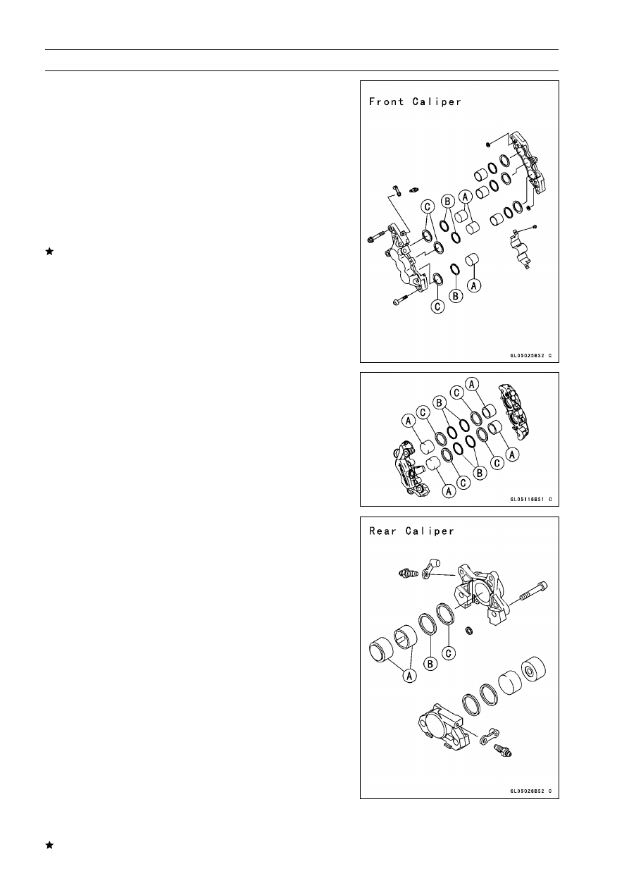
Caliper Fluid Seal Damage

The fluid seals (piston seal) [C] is placed around the pis-

ton [A] to maintain clearance between the pad and the disc.
If the seal is in a poor condition, it could lead the pad to wear
excessively or the brake to drag, which may cause the tem-
perature of the discs or the brake fluid to increase.

Replace the fluid seal if it exhibits any of the conditions
listed below.

Brake fluid leakage around the pad.

Brakes overheat.

Considerable difference in inner and outer pad wear.

Seal and piston are stuck together.
If the fluid seal is replaced, replace the dust seals [B] as
well. Also, replace all seals every other time the pads are
changed.

For ZX1200-B3 model

; as shown in the figure.

Caliper Dust Seal Damage

Check that the dust seals [B] is not cracked, worn,
swollen, or otherwise damaged.

If it show any damage, remove the caliper bracket and
replace it.

Pistons [A]
Fluid Seals [C]

Caliper Piston and Cylinder Damage

Visually inspect the pistons and cylinder surfaces.
Replace the caliper if the cylinder and piston are badly
scores or rusty.

BRAKES 12-17

Brake Pads

Front Brake Pad Removal (ZX1200-B1/B2)

Unscrew the pad spring bolts [A], and remove the pad
spring [B].

Draw out the clip [A], and take off the pad pin [B].

Remove the brake pads [C].

Front Brake Pad Removal (ZX1200-B3

)

Loosen:

Pad Pins [B]

Remove:

Caliper Mounting Bolts [A]

Remove:

Pad Pin [A]
Pad Spring [B]
Brake Pads [C]

12-18 BRAKES

Brake Pads

Front Brake Pad Installation (ZX1200-B1/B2)

Push the caliper pistons in by hand as far as they will go.

Install the brake pads.

Install the pad pin and clip. The clip must be "outside" of
the pads.

Install the caliper (see Front Caliper Installation).

Torque - Front Brake Pad Spring Bolts: 3.0 N·m (0.30 kgf·m,

27 in·lb)

WARNING

Do not attempt to drive the motorcycle until a full
brake lever is obtained by pumping the brake lever
until the pads are against the disc. The brake will
not function on the first application of the lever if
this is not done.

Front Brake Pad Installation (ZX1200-B3

)

Push the caliper pistons in by hand as far as they will go.

Install the outside pad [A] and insert the pin [B] as shown.

Set:

Inside Pad [A]
Pad Spring [B]

Pushing the pin holder [C] to hole of the pad and insert
the pin.

Torque - Front Brake Pad Pins: 15 N·m (1.5 kgf·m, 11 ft·lb)

WARNING

Do not attempt to drive the motorcycle until a full
brake lever is obtained by pumping the brake lever
and the pads are against the disc. The brake will
not function on the first application of the lever if
this is not done.

Rear Brake Pad Removal

Unscrew the caliper mounting bolts.

Detach the caliper from the disc.

Remove the piston pad cover [A].

Draw out the clip [B] upward.

BRAKES 12-19

Brake Pads

Pushing either ends [A] of the pad spring lightly, take off
the pad pins [B] one by one.

Remove the pad springs [C] and brake pads.

Rear Brake Pad Installation

Push the caliper piston in by hand as far as it will go.

Put the pads [A] in the caliper to insert either pin [B] into
both holes of pad.

Put the anti-rattle springs [C] under inserted pins.

Insert other side pad pin [E] into both holes of pad with
pushing both spring ends [D].

Insert the clip [A]. The clip must be "outside" of the pads.

Install the caliper (see Rear Caliper Installation).

WARNING

Do not attempt to drive the motorcycle until a full
brake pedal is obtained by pumping the brake pedal
until the pads are against the disc. The brake will
not function on the first application of the pedal if
this is not done.

Brake Pad Lining Wear

Refer to the Brake Pad Wear Inspection in the Periodic
Maintenance chapter.

12-20 BRAKES

Master Cylinder

Front Master Cylinder Removal

Disconnect the front brake light switch connectors [A].

Remove the banjo bolt [B] to disconnect the brake hose
from the master cylinder [C] (see Brake Hose Removal/In-
stallation).

Unscrew the clamp bolts [A], and take off the master cylin-
der as an assembly with the reservoir, brake lever, and
brake switch installed.

Front Master Cylinder Installation

Install the front master cylinder so that the punch mark [A]
of the handlebar is aligned with the mating surface [B] of
the master cylinder clamp to level the reservoir.

The master cylinder clamp must be installed with the ar-
row mark [A] upward.

Tighten the upper clamp bolt [B] first, and then the lower
clamp bolt [C]. There will be a gap at the lower part of the
clamp after tightening.

Torque - Front Master Cylinder Clamp Bolts: 8.8 N·m (0.90

kgf·m, 78 in·lb)

Replace the washers on each side of the hose fitting with
new ones.

Tighten the brake hose banjo bolt.

Torque - Brake Hose Banjo Bolt: 34 N·m (3.5 kgf·m, 25 ft·lb)

Bleed the brake line (see Bleeding the Brake Line).

Check the brake for good braking power, no brake drag,
and no fluid leakage.

BRAKES 12-21

Master Cylinder

Rear Master Cylinder Removal

Unscrew the brake hose banjo bolt [A] on the master cylin-
der (see Brake Hose Removal/Installation).

Pull off the reservoir hose lower end [B], and drain the
brake fluid into a container.

Loosen the master cylinder mounting bolts [C] lightly.

Remove the cotter pin [D].

NOTE

Pull off the joint pin while pressing down the brake
pedal.

Unscrew the master cylinder mounting bolts, and remove
the master cylinder.

Rear Master Cylinder Installation

Replace the cotter pin [A] with a new one.

Replace the washers on each side of hose fitting with new
ones.

Tighten the following bolts.

Torque - Rear Master Cylinder Mounting Bolts: 25 N·m (2.5

kgf·m, 18 ft·lb)

Brake Hose Banjo Bolt: 34 N·m (3.5 kgf·m, 25 ft·lb)

Bleed the brake line (see Bleeding the Brake Line).

Check the brake for good braking power, no brake drag,
and no fluid leakage.

Front Master Cylinder Disassembly

Remove the front master cylinder (see Front Master Cylin-
der Removal).

Remove the reservoir cap and diaphragm, and pour the
brake fluid into a container.

Unscrew the locknut and pivot bolt, and remove the brake
lever.

Pull the dust cover [A] out of place, and remove the circlip
[B].

Special Tool - Inside Circlip Pliers: 57001-143

Pull out the piston [C], secondary cup [D], primary cup [E],
and return spring [F].

CAUTION

Do not remove the secondary cup from the piston
since removal will damage it.

12-22 BRAKES

Master Cylinder

Rear Master Cylinder Disassembly

Remove the rear master cylinder (see Rear Master Cylin-
der Removal).

Slide the dust cover [F] on the push rod out of place, and
remove the circlip [E].

Special Tool - Inside Circlip Pliers: 57001-143

NOTE

Do not remove the push rod clevis [G] for master cylin-
der disassembly since removal requires brake pedal po-
sition adjustment.

Pull out the push rod with the piston stop.

Take off the piston [A], secondary cup [B], primary cup [C],
and return spring [D].

CAUTION

Do not remove the secondary cup from the piston
since removal will damage it.

Master Cylinder Assembly

Before assembly, clean all parts including the master
cylinder with brake fluid or alcohol.

CAUTION

Except for the disc pads and disc, use only disc
brake fluid, isopropyl alcohol, or ethyl alcohol for
cleaning brake parts. Do not use any other fluid for
cleaning these parts, Gasoline, engine oil, or any
other petroleum distillate will cause deterioration of
the rubber parts. Oil Spilled on any part will be dif-
ficult to wash off completely, and will eventually de-
teriorate the rubber used in the disc brake.

Apply brake fluid to the removed parts and to the inner
wall of the cylinder.

Take care not to scratch the piston or the inner wall of the
cylinder.

Apply silicone grease (ex. PBC grease) to the push rod
end, the brake lever end (piston contact portion) and the
brake lever pivot bolt journal.

Tighten the brake lever pivot bolt and the locknut.

Torque - Brake Lever Pivot Bolt: 1.0 N·m (0.10 kgf·m, 9

in·lb)

Brake Lever Pivot Bolt Locknut: 6.0 N·m (0.60

kgf·m, 52 in·lb)

BRAKES 12-23

Master Cylinder

Master Cylinder Inspection (Visual Inspection)

Disassemble the front and rear master cylinders.

Check that there are no scratches, rust or pitting on the
inner wall of each master cylinder [A] and on the outside
of each piston [B].
If a master cylinder or piston shows any damage, replace
them.

Inspect the primary [C] and secondary [D] cups.
If a cup is worn, damaged, softened (rotted), or swollen,
the piston assembly should be replaced to renew the
cups.
If fluid leakage is noted at the brake lever, the piston as-
sembly should be replaced to renew the cups.

Front Master Cylinder [J]

Check the dust covers [E] for damage.
If they are damaged, replace them.

Check the piston return springs [F] for any damage.
If the springs are damaged, replace them.

Check that relief [G] and supply [H] ports are not plugged.
If the relief port becomes plugged, the brake pads will
drag on the disc. Blow the ports clean with compressed
air.

Rear Master Cylinder [K]

12-24 BRAKES

Brake Discs

Brake Disc Removal

Remove the wheel (see Wheels/Tires chapter).

Unscrew the mounting bolts [A], and take off the disc [B].

Brake Disc Installation

Install the brake disc on the wheel so that the marked [A]
side faces out.

Apply a non-permanent locking agent to the threads of
the rear brake disc mounting bolts.

Tighten the mounting bolts [B].

Torque - Brake Disc Mounting Bolts: 27 N·m (2.8 kgf·m, 20

ft·lb)

Brake Disc Wear

Measure the thickness of each disc at the point where it
has worn the most.
Replace the disc [A] if it has worn past the service limit.

Measuring Area [B]

Front Disc Thickness

Standard:

ZX1200-B1/B2 4.8

5.1 mm (0.19

0.20 in.)

ZX1200-B3

5.8

6.2 mm (0.23

0.24 in.)

Service Limit:

ZX1200-B1/B2 4.5 mm (0.18 in.)
ZX1200-B3

5.5 mm (0.22 in.)

Rear Disc Thickness

Standard:

ZX1200-B1/B2 5.8

6.0 mm (0.23

0.24 in.)

ZX1200-B3

5.9

6.1 mm (0.23

0.24 in.)

Service Limit:

5.0 mm (0.20 in.)

Brake Disc Warp

Jack up the motorcycle so that the wheel is off the ground.

Special Tool - Jack: 57001-1238

For front disc inspection, turn the handlebar fully to one
side.

Set up a dial gauge against the disc [A] as shown and
measure disc runout.

Turn the wheel by hand. [B]

If runout exceeds the service limit, replace the disc.

Disc Runout

Standard:

0.15 mm (0.0059 in.) or less

Service Limit:

0.3 mm (0.01 in.)

BRAKES 12-25

Brake Fluid

Brake Fluid Level Inspection

Refer to the Brake Fluid Level Inspection in the Periodic
Maintenance chapter.

Brake Fluid Change

Refer to the Brake Fluid Change in the Periodic Mainte-
nance chapter.

Bleeding the Brake Line

The brake fluid has a very low compression coefficient so

that almost all the movement of the brake lever or pedal
is transmitted directly to the caliper for braking action. Air,
however, is easily compressed. When air enters the brake
lines, brake lever or pedal movement will be partially used
in compressing the air. This will make the lever or pedal feel
spongy, and there will be a loss in braking power.

WARNING

Be sure to bleed the air from the brake line when-
ever brake lever or pedal action feels soft or
spongy after the brake fluid is changed, or when-
ever a brake line fitting has been loosened for any
reason.

NOTE

The procedure to bleed the front brake line is as follows.
Bleeding the rear brake line is the same as for the front
brake.

Remove the reservoir cap, and diaphragm.

Fill the reservoir with fresh brake fluid to the upper level
line in the reservoir.

With the reservoir cap off, slowly pump the brake lever
several times until no air bubbles can be seen rising up
through the fluid from the holes at the bottom of the reser-
voir.

Bleed the air completely from the master cylinder by this
operation.

Remove the rubber cap from the bleed valve on the
caliper.

Attach a clear plastic hose to the bleed valve, and run the
other end of the hose into a container.

Bleed the brake line and the caliper as follows:

Repeat this operation until no more air can be seen com-
ing out into the plastic hose.

1. Pump the brake lever until it becomes hard, and apply

the brake and hold it [A].

2. Quickly open and close [B] the bleed valve while holding

the brake applied.

3. Release the brake [C].

12-26 BRAKES

Brake Fluid

NOTE

The fluid level must be checked often during the bleed-
ing operation and replenished with fresh brake fluid as
necessary. If the fluid in the reservoir runs completely
out any time during bleeding, the bleeding operation
must be done over again from the beginning since air
will have entered the line.

Tap the brake hose lightly from the caliper to the reser-
voir for more complete bleeding.

Front Brake: Repeat the above steps for the other
caliper.

Rear Brake: Repeat the above steps for the other bleed
valve.

Remove the clear plastic hose.

Install the reservoir cap.

Tighten the front reservoir cap screws.

Torque - Front Reservoir Cap Screws: 1.5 N·m (0.15 kgf·m,

13 in·lb)

Tighten the bleed valve, and install the rubber cap.

Torque - Bleed Valve: 7.8 N·m (0.80 kgf·m, 69 in·lb)

Check the fluid level.

After bleeding is done, check the brake for good braking
power, no brake drag, and no fluid leakage.

BRAKES 12-27

Brake Fluid

WARNING

When working with the disc brake, observe the pre-
cautions listed below.

1. Never reuse old brake fluid.
2. Do not use fluid from a container that has been left

unsealed or that has been open for a long time.

3. Do not mix two types and brands of fluid for use in

the brake. This lowers the brake fluid boiling point
and could cause the brake to be ineffective. It may
also cause the rubber brake parts to deteriorate.

4. Don’t leave the reservoir cap off for any length of

time to avoid moisture contamination of the fluid.

5. Don’t change the fluid in the rain or when a strong

wind is blowing.

6. Except for the disc pads and disc, use only disc

brake fluid, isopropyl alcohol, or ethyl alcohol for
cleaning brake parts. Do not use any other fluid for
cleaning these parts. Gasoline, engine oil, or any
other petroleum distillate will cause deterioration of
the rubber parts. Oil spilled on any part will be diffi-
cult to wash off completely and will eventually dete-
riorate the rubber used in the disc brake.

7. When handing the disc pads or disc, be careful that

no disc brake fluid or any oil gets on them. Clean off
any fluid or oil that inadvertently gets on the pads or
disc with a high-flash point solvent. Do not use one
which will leave an oily residue. Replace the pads
with new ones if they cannot be cleaned satisfacto-
rily.

8. Brake fluid quickly ruins painted surfaces; any

spilled fluid should be completely wiped up imme-
diately.

9. If any of the brake line fittings or the bleed valve is

opened at any time, the

AIR MUST BE BLED FROM

THE BRAKE LINE

.

12-28 BRAKES

Brake Hoses

Brake Hose Removal/Installation

CAUTION

Brake fluid quickly ruins painted or plastic sur-
faces; any spilled fluid should be completely wiped
up immediately with wet cloth.

When removing the brake hose, take care not to spill the
brake fluid on the painted or plastic parts.

When removing the brake hose, temporarily secure the
end of the brake hose to some high place to keep fluid
loss to a minimum.

There are washers on each side of the brake hose fitting.
Replace them with new ones when installing.

When installing the hoses, avoid sharp bending, kinking,
flattening or twisting, and route the hoses according to
Hose Routing section in General Information chapter.

Tighten the banjo bolts at the hose fittings.

Torque - Brake Hose Banjo Bolts: 34 N·m (3.5 kgf·m, 25

ft·lb)

Bleed the brake line after installing the brake hose (see
Bleeding the Brake Line).

Brake Hose Inspection

Refer to the Brake Hose, Connection Inspection in the
Periodic Maintenance chapter.

SUSPENSION 13-1

13

Suspension

Table of Contents

Exploded View........................................................................................................................

13-2

Specifications .........................................................................................................................

13-4

Front Fork ...............................................................................................................................

13-5

Rebound Damping Force Adjustment...............................................................................

13-5

Compression Damping Force Adjustment ........................................................................

13-5

Spring Preload Adjustment ...............................................................................................

13-6

Front Fork Removal (each fork leg) ..................................................................................

13-7

Front Fork Installation .......................................................................................................

13-7

Fork Oil Change................................................................................................................

13-7

Front Fork Disassembly ....................................................................................................

13-8

Front Fork Assembly.........................................................................................................

13-8

Inner Tube Inspection .......................................................................................................

13-9

Dust Seal Inspection .........................................................................................................

13-10

Spring Tension ..................................................................................................................

13-10

Rear Shock Absorber .............................................................................................................

13-11

Rebound Damping Force Adjustment...............................................................................

13-11

Compression Damping Force Adjustment ........................................................................

13-11

Spring Preload Adjustment ...............................................................................................

13-12

Rear Shock Absorber Removal ........................................................................................

13-12

Rear Shock Absorber Installation .....................................................................................

13-13

Rear Shock Absorber Scrapping ......................................................................................

13-13

Swingarm................................................................................................................................

13-14

Swingarm Removal...........................................................................................................

13-14

Swingarm Installation........................................................................................................

13-15

Swingarm Bearing Removal .............................................................................................

13-15

Swingarm Bearing Installation ..........................................................................................

13-16

Swingarm Bearing, Sleeve Inspection ..............................................................................

13-16

Swingarm Pivot Lubrication ..............................................................................................

13-16

Chain Slider Inspection .....................................................................................................

13-16

Tie-Rod, Rocker Arm..............................................................................................................

13-17

Tie-Rod Removal ..............................................................................................................

13-17

Tie-Rod Installation ...........................................................................................................

13-17

Rocker Arm Removal........................................................................................................

13-17

Rocker Arm Installation.....................................................................................................

13-17

Needle Bearing Inspection................................................................................................

13-18

Tie-Rod, Rocker Arm Sleeve Inspection...........................................................................

13-18

Uni-track Linkage Lubrication ...........................................................................................

13-18

13-2 SUSPENSION

Exploded View

T1: 20 N·m (2.0 kgf·m, 15 ft·lb)
T2: 23 N·m (2.3 kgf·m, 17 ft·lb)
T3: 28 N·m (2.8 kgf·m, 21 ft·lb)
T4: 40 N·m (4.0 kgf·m, 30 ft·lb)

A: ZX1200-B1/B2 model

AL: Tighten the two clamp bolts alternately two times to ensure even tightening torque.

L: Apply a non-permanent locking agent.

R: Replacement Parts

SUSPENSION 13-3

Exploded View

T5: 34 N·m (3.5 kgf·m, 25 ft·lb)
T6: 98 N·m (10 kgf·m, 72 ft·lb)
T7: 127 N·m (13 kgf·m, 94 ft·lb)
T8: 59 N·m (6.0 kgf·m, 44 ft·lb)

A: ZX1200-B1

B3

G: Apply grease.

13-4 SUSPENSION

Specifications

Item

Standard

Front Fork (per One Unit)

Fork Inner Tube Outside Diameter

43 mm (1.7 in.)

Air Pressure

Atmospheric pressure (Non-adjustable)

Rebound Damper Setting:

ZX1200-B1/B2

1 1/2 turns backward from the fully tightened position

(Usable Range: 0

←→

3 turns)

ZX1200-B3

7th click from the first click of the fully clockwise position

(Usable Range: 0

←→

13 clicks)

Compression Damper Setting:

ZX1200-B1/B2

2 1/4 turns backward from the fully tightened position

(Usable Range: 0

←→

3 turns)

ZX1200-B3

Fully turned counterclockwise position

(Usable Range: 0

←→

Fully turned counterclockwise)

Fork Spring Preload Setting

Adjuster protrusion is 17 mm (0.67 in.)

(Usable Range: 4

19 mm (0.16

0.75 in.))

Fork Oil Viscosity

KAYABA KHL15-10 (SAE 0 W) or equivalent

Fork Oil Capacity

490 ±4 mL (16.6 ±0.1 US oz) (completely dry) approx.
420 mL (14.2 US oz) (when changing oil)

Fork Oil Level

Fully compressed, without fork spring, below from outer tube
top 93 ±2 mm (3.66 ±0.08 in.)

Fork Spring Free Length

251.5 mm (9.902 in.) (Service limit 246 mm (9.69 in.))

Rear Shock Absorber

Rebound Damper Set

3 turns backward from the fully tightened position

(Usable Range: 0

←→

5 turns)

Compression Damper Set

2 1/4 turns backward from the fully tightened position

(Usable Range: 0

←→

5 turns)

Spring Setting Position:

Standard

Spring length 177 mm (6.97 in.)

Usable Range

Spring length 191.5 mm (7.54 in.) to 170 mm (6.69 in.)

(weaker to stronger)

Gas Pressure

980 kPa (10 kgf/cm², 142 psi, Non-adjustable)

Special Tools - Inside Circlip Pliers: 57001-143

Oil Seal and Bearing Remover: 57001-1058
Bearing Driver Set: 57001-1129
Jack: 57001-1238
Fork Piston Rod Puller, M12 × 1.25: 57001-1289
Fork Oil Level Gauge: 57001-1290
Fork Oil Seal Driver, 43: 57001-1530
Socket Wrench: 57001-1370
Fork Cylinder Holder: 57001-1443
Fork Spring Compressor Set: 57001-1452
Hook Wrench: 57001-1512
Fork Spring Compressor: 57001-1587
Clamp: 57001-1613

SUSPENSION 13-5

Front Fork

Rebound Damping Force Adjustment

To adjust the rebound damping force, turn the rebound
damping adjuster [A] to suit you best.

The standard adjuster setting for the average-build rider
of 68 kg (150 lb) with no passenger and no accessories is
the

1 1/2 turns backward

from the fully tightened position

(ZX1200-B1/B2).

The standard adjuster setting for the average-build rider
of 68 kg (150 lb) with no passenger and no accessories
is the 7th click from the first click of the fully clockwise
position (ZX1200-B3

).

WARNING

If both adjusters are not adjusted equally, handling
may be impaired and a hazardous condition may
result.

The damping force can be left soft for average riding. But
it should be adjusted harder for high speed riding or riding
with a passenger. If the damping feels too soft or too stiff,
adjust it in accordance with the following table.

Rebound Damping Force Adjustment
ZX1200-B1/B2

Adjuster

Position

Damping

Force

Setting

Load

Road

Speed

3

Weak

Soft

Light

Good

Low

0

Strong

Hard

Heavy

Bad

High

ZX1200-B3

Adjuster

Position

Damping

Force

Setting

Load

Road

Speed

13

Weak

Soft

Light

Good

Low

0

Strong

Hard

Heavy

Bad

High

Compression Damping Force Adjustment

To adjust the compression damping force, turn the com-
pression damping adjuster [A] to suit you best.

The standard adjuster setting for the average-build rider
of 68 kg (150 lb) with no passenger and no accessories is
the

2 1/4 turns backward

from the fully tightened position

(ZX1200-B1/B2).

The standard adjuster setting for the average-build rider
of 68 kg (150 lb) with no passenger and no accessories is
the fully turned counterclockwise position (ZX1200-B3

).

WARNING

If both adjusters are not adjusted equally, handling
may be impaired and a hazardous condition may
result.

13-6 SUSPENSION

Front Fork

The damping force can be left soft for average riding. But
it should be adjusted harder for high speed riding or riding
with a passenger. If the damping feels too soft or too stiff,
adjust it in accordance with the following table.

Compression Damping Force Adjustment
ZX1200-B1/B2

Adjuster

Position

Damping

Force

Setting

Load

Road

Speed

3

Weak

Soft

Light

Good

Low

0

Strong

Hard

Heavy

Bad

High

ZX1200-B3

Adjuster

Position

Damping

Force

Setting

Load

Road

Speed

*

Weak

Soft

Light

Good

Low

0

Strong

Hard

Heavy

Bad

High

* Full turned counterclockwise

Spring Preload Adjustment

Turn the spring preload adjuster [A] to change spring
preload setting.

The standard adjuster setting for the average-build rider
of 68 kg (150 lb) with no passenger and no accessories
is the 17 mm (0.67 in.) [B] from top as shown.

Adjuster Protrusion (from top)

Standard:

17 mm (0.67 in.)

Usable Range:

4

19 mm (0.16

0.75 in.)

WARNING

If both adjusters are not adjusted equally, handling
may be impaired and a hazardous condition may
result.

The spring preload can be left soft for average riding. But
it should be adjusted harder for high speed riding or riding
with a passenger. If the spring action feels too soft or too
stiff, adjust it in accordance with the following table.

Spring Action

Adjuster

Position

Damping

Force

Setting

Load

Road

Speed

19 mm

(0.75 in.)

Weak

Soft

Light

Good

Low

4 mm

Strong

Hard

Heavy

Bad

High

(0.16 in.)

SUSPENSION 13-7

Front Fork

Front Fork Removal (each fork leg)

Remove:

Front Wheel (see Wheels/Tires chapter)
Front Fender (see Frame chapter)

Loosen the upper fork clamp bolt [B] and fork top plug [A]
beforehand if the fork leg is to be disassembled.

NOTE

Loosen the top plug after loosening the upper fork
clamp bolt.

Loosen the upper fork clamp bolt [A] and lower fork clamp
bolts [B].

With a twisting motion, work the fork leg down and out.

Front Fork Installation

Install the fork so that the top end [A] of the outer tube is
flush with the upper surface [B] of the steering stem head
bracket.

Tighten the lower fork clamp bolts and fork top plug.

Torque - Front Fork Clamp Bolts (Lower): 20 N·m (2.0

kgf·m, 15 ft·lb)

Front Fork Top Plug: 23 N·m (2.3 kgf·m, 17 ft·lb)

NOTE

Tighten the two clamp bolts alternately two times to en-
sure even tightening torque.

Tighten the upper fork clamp bolt.

Torque - Front Fork Clamp Bolt (Upper): 20 N·m (2.0 kgf·m,

15 ft·lb)

NOTE

Tighten the top plug before tightening the upper fork
clamp bolt.

Install the removed parts (see appropriate chapters).

Adjust the spring preload and the damping force.

Fork Oil Change

The oil should be change in accordance with the Periodic

Maintenance chapter.

Refer to the Front Fork Oil Change in the Periodic Main-
tenance chapter.

13-8 SUSPENSION

Front Fork

Front Fork Disassembly

Remove the front fork (see Front Fork Removal).

Drain the fork oil (see Fork Oil Change in the Periodic
Maintenance chapter).

Hold the front fork in a vise [A].

Stop the cylinder [B] from turning by using the fork cylinder
holder [C].

Special Tool - Fork Cylinder Holder: 57001-1443

Unscrew the Allen bolt [D], then take the bolt and gasket
out of the bottom of the inner tube.

Take the cylinder unit [A].

Do not disassemble the cylinder unit.

Separate the outer tube from the inner tube.

Pull out the dust seal.

Remove the retaining ring [A] from the outer tube.

Remove the oil seal [B] and washer [C].

Front Fork Assembly

Replace the following parts with a new one.

Oil Seal
Bottom Allen Bolt Gasket

Insert the cylinder unit [A] into the inner tube [B].

Stop the cylinder from turning by using the fork cylinder
holder.

Special Tool - Fork Cylinder Holder: 57001-1443

Apply a non-permanent locking agent to the Allen bolt and
tighten it.

Torque - Front Fork Bottom Allen Bolt: 40 N·m (4.0 kgf·m,

30 ft·lb)

SUSPENSION 13-9

Front Fork

Install the following parts into the inner tube [A].

Dust Seal [B]
Circlip [C]
Oil Seal [D]
Washer [E]

Insert the inner tube to the outer tube.

After installing the washer, install the oil seal [A] by using
the fork oil seal driver [B].

Special Tool - Fork Oil Seal Driver, 43: 57001-1530

Install the circlip and dust seal.

Pour in the specified type of oil (see Fork Oil Change in
the Periodic Maintenance chapter).

Inner Tube Inspection

Visually inspect the inner tube [A], and repair any dam-
age.

Nicks or rust damage can sometimes be repaired by using
a wet-stone to remove sharp edges or raised areas which
cause seal damage.
If the damage is not repairable, replace the inner tube.
Since damage to the inner tube damages the oil seal,
replace the oil seal whenever the inner tube is repaired
or replaced.

ZX1200-B1/B2 [B]
ZX1200-B3 [C]

CAUTION

If the inner tube is badly bent or creased, replace
it.

Excessive bending, followed by subsequent

straightening, can weaken the inner tube.

Temporarily assemble the inner and outer tubes, and
pump them back and forth manually to check for smooth
operation.

If you feel binding or catching, the inner and outer tubes
must be replaced.

WARNING

A straightened inner or outer fork tube may fall in
use, possibly causing an accident. Replace a badly
bent or damaged inner or outer tube and inspect the
other tube carefully before reusing it.

13-10 SUSPENSION

Front Fork

Dust Seal Inspection

Inspect the dust seals [A] for any signs of deterioration or
damage.
Replace it if necessary.

Spring Tension

Since a spring becomes shorter as it weakens, check its
free length [A] to determine its condition.
If the spring of either fork leg is shorter than the service
limit, it must be replaced. If the length of a replacement
spring and that of the remaining spring vary greatly, the
remaining spring should also be replaced in order to keep
the fork legs balanced for motorcycle stability.

Spring Free Length

Standard:

251.5 mm (9.902 in.)

Service Limit:

246 mm (9.69 in.)

SUSPENSION 13-11

Rear Shock Absorber

Rebound Damping Force Adjustment

To adjust the rebound damping force, turn the rebound
damping adjuster [A] to suit you best.

The standard adjuster setting for an average-build rider
of 68 kg (150 lb) with no passenger and no accessories
is the

3 turns backward

from the fully tightened position.

If the damping feels too soft or too stiff, adjust it.

Rebound Damping Force Adjustment

Adjuster

Position

Damping

Force

Setting

Load

Road

Speed

5

Weak

Soft

Light

Good

Low

0

Strong

Hard

Heavy

Bad

High

Compression Damping Force Adjustment

To adjust the compression damping force, turn the com-
pression damping adjuster [A] on the gas reservoir to suit
you best.

The standard adjuster setting for the average-build rider
of 68 kg (150 lb) with no passenger and no accessories
is the

2 1/4 turns backward

from the fully tightened po-

sition.

The damping force can be left soft for average riding. But
it should be adjusted harder for high speed riding or riding
with a passenger. If the damping feels too soft or too stiff,
adjust it in accordance with the following table.

Compression Damping Force Adjustment

Adjuster

Position

Damping

Force

Setting

Load

Road

Speed

5

Weak

Soft

Light

Good

Low

0

Strong

Hard

Heavy

Bad

High

13-12 SUSPENSION

Rear Shock Absorber

Spring Preload Adjustment

Remove the rear shock absorber from the frame to mea-
sure the spring length (see Rear Shock Absorber Re-
moval).

Loosen the locknut [B] and turn out the adjusting nut [A]
to free the spring.

Special Tool - Hook Wrench T = 3.2 R37: 57001-1522

Measure the spring free length [C].

Spring Free Length

Standard:

191.5 mm (7.54 in.)

Spring Preload Setting

Standard:

Spring length 177 mm (6.97 in.)

Usable Range: Spring length 191.5 (7.54 in.) to 170

mm (6.69 in.) (weaker to stronger)

The standard adjusting nut setting for an average-build
rider of 68 kg (150 lb) with no passenger and no acces-
sories is 177 mm (6.97 in.) spring length.

To adjust the spring preload, turn in the adjusting nut to
the desired position and tighten the locknut using by hook
wrenches [A] with the rear shock absorber attached the
frame.

Remove the chain cover (see Final Drive chapter) and left
foot guard for turning the hook wrench easily.
If the spring action feels too soft or too stiff, adjust it.

Special Tool - Hook Wrench T = 3.2 R37: 57001-1522

Spring Adjustment

Adjuster

Position

Damping

Force

Setting

Load

Road

Speed

191.5 mm

(7.54 in.)

Weak

Soft

Light

Good

Low

170 mm

Strong

Hard

Heavy

Bad

High

(6.69 in.)

Rear Shock Absorber Removal

Remove the lower fairings (see Frame chapter).

Raise the rear wheel off the ground with the jack.

Special Tool - Jack: 57001-1238

Remove:

Upper Tie-Rod Nut and Bolt [A]
Lower Shock Absorber Nut and Bolt [B]

SUSPENSION 13-13

Rear Shock Absorber

Remove:

Upper Shock Absorber Nut
Upper Shock Absorber Bolt [A]

Lift up [B] the rear fender front with a suitable bar or your
hand to the arrow direction, and then pull out the absorber
Bolt.

Remove the shock absorber from under.

Rear Shock Absorber Installation

Pack the rocker arm needle bearings with grease.

Tighten the following nuts:

Torque - Rear Shock Absorber Nuts: 34 N·m (3.5 kgf·m, 25

ft·lb)

Tie-Rod Nuts: 59 N·m (6.0 kgf·m, 44 ft·lb)

Rear Shock Absorber Scrapping

WARNING

Since the reservoir tank of the rear shock absorber
contains nitrogen gas, do not incinerate the reser-
voir tank without first releasing the gas or it may
explode.

Remove the shock absorber (see Rear Shock Absorber
Removal).

Take off the cap [A] of reserve tank and release the nitro-
gen gas from the valve of the gas reservoir completely.

WARNING

Since the high pressure gas is dangerous, do not
point the valve toward your face or body.

13-14 SUSPENSION

Swingarm

Swingarm Removal

Remove the lower fairings (see Frame chapter).

Remove the side stand mounting bracket (see Frame
chapter).

Raise the rear wheel of the ground with the jack.

Special Tool - Jack: 57001-1238

Remove:

Rear Wheel (see Wheels/Tires chapter)
Chain Cover (see Final Drive chapter)
Rear Shock Absorber (see this chapter)
Brake Hose Clamps [A]

Unscrew the swingarm pivot shaft locknut [A].

Unscrew the swingarm pivot shaft nut [A].

Special Tool - Socket Wrench [B]: 57001-1370

Unscrew the swingarm pivot shaft [A] with the Allen
wrench.

Pull off the pivot shaft and remove the swingarm.

SUSPENSION 13-15

Swingarm

Swingarm Installation

Apply plenty of grease to the ball bearing, needle bearings
and grease seals.

Install the collars [A].

Place the right collar [A] on the stopper [B] inside the
frame [C].

Insert the pivot shaft into the frame from the right side.

Tighten the pivot shaft so that the clearance between the
collar and the frame come to zero mm [D].

Tighten the pivot nut.

Torque - Swingarm Pivot Nut: 127 N·m (13 kgf·m, 94 ft·lb)

Tighten the pivot locknut.

Torque - Swingarm Pivot Shaft Locknut: 98 N·m (10 kgf·m,

72 ft·lb)

Install the side stand bracket.

Torque - Side Stand Mounting Bracket Bolts: 49 N·m (5.0

kgf·m, 36 ft·lb)

Install the removed parts (see appropriate chapters).

Swingarm Bearing Removal

Remove:

Swingarm
Collars [A]
Grease Seals [B]
Sleeve [C]
Circlip (right side) [D]

Special Tool - Inside Circlip Pliers: 57001-143

Remove the ball bearing and needle bearings using the
oil seal & bearing remover [A].

Special Tool - Oil Seal & Bearing Remover: 57001-1058

13-16 SUSPENSION

Swingarm

Swingarm Bearing Installation

Apply plenty of grease to the ball bearing and needle
bearings.

Install the needle bearings so that the manufacturer’s
marks face out.

Install the ball bearing so that the manufacturer’s marks
faces out.

Special Tool - Bearing Driver Set: 57001-1129 [A]

Swingarm Bearing, Sleeve Inspection

CAUTION

Do not remove the bearings for inspection. Re-
moval may damage them.

Inspect the needle bearings [A] and ball bearing [B] in-
stalled in the swingarm.

The rollers and ball in a bearing normally wear very little,
and wear is difficult to measure. Instead of measuring,
visually inspect the bearing for abrasion, discoloration, or
other damage.
If the needle bearing, ball bearing, and sleeve show any
sings of abnormal wear, discoloration, or damage, re-
place them as a set.

Swingarm Pivot Lubrication

Refer to the Swingarm Pivot Lubrication in the Periodic
Maintenance chapter.

Chain Slider Inspection

Visually inspect the chain slider [A].
Replace the chain slider if it shows any signs of abnormal
wear or damage.

SUSPENSION 13-17

Tie-Rod, Rocker Arm

Tie-Rod Removal

Remove the lower fairings (see Frame chapter).

Remove the side stand mounting bracket (see Frame
chapter).

Raise the rear wheel off the ground with the jack.

Special Tool - Jack: 57001-1238

Remove:

Upper Tie-Rod Bolts and Nut [A]
Lower Rear Shock Absorber Bolt and Nut [B]

Remove:

Lower Tie-Rod Nut [A]
Rocker Arm nut [B]

Remove the muffler body mounting bolt (see Engine Top
End chapter).

Remove the rocker arm bolt pushing down the muffler.

Pull out the lower tie-rod bolt from the rocker arm.

Tie-Rod Installation

Apply grease to the inside of the needle bearings and oil
seals.

Install the tie-rods so that the marked side faces outer
side.

Tighten each bolts.

Torque - Rocker Arm Nut: 34 N·m (3.5 kgf·m, 25 ft·lb)

Tie-Rod Nuts: 59 N·m (6.0 kgf·m, 44 ft·lb)
Lower Rear Shock Absorber Nut: 34 N·m (3.5

kgf·m, 25 ft·lb)

Rocker Arm Removal

Remove the lower fairings (see Frame chapter).

Remove the side stand mounting bracket (see Frame
chapter).

Raise the rear wheel off the ground with the jack.

Special Tool - Jack: 57001-1238

Remove:

Upper Tie-Rod Bolt and Nut
Lower Rear Shock Absorber Bolt and Nut
Muffler Body Mounting Bolt
Lower Tie-Rod Nut [A]
Rocker Arm Bolt and Nut [B]
Rocker Arm [C]

Remove the rocker arm bolt pushing down the muffler.

Rocker Arm Installation

Apply grease to the inside of the needle bearings and oil
seal lips, and add grease to the grease nipple.

Tighten the rocker arm nut, tie-rod nut and shock absorber
lower nut.

Torque - Rocker Arm Nut: 34 N·m (3.5 kgf·m, 25 ft·lb)

Tie-Rod Nuts: 59 N·m (6.0 kgf·m, 44 ft·lb)
Lower Rear Shock Absorber Nut: 34 N·m (3.5

kgf·m, 25 ft·lb)

13-18 SUSPENSION

Tie-Rod, Rocker Arm

Needle Bearing Inspection

If there is any doubt as to the condition of either needle
bearing, replace the bearing and sleeve as a set, and/or
add grease to the grease nipple.

Tie-Rod, Rocker Arm Sleeve Inspection

If there is visible damage, replace the sleeve and needle
bearing as a set.

Uni-track Linkage Lubrication

Refer to the Uni-track Linkage Lubricate in the Periodic
Maintenance chapter.

STEERING 14-1

14

Steering

Table of Contents

Exploded View........................................................................................................................

14-2

Specifications .........................................................................................................................

14-3

Steering ..................................................................................................................................

14-4

Steering Inspection ...........................................................................................................

14-4

Steering Adjustment..........................................................................................................

14-4

Steering Stem.........................................................................................................................

14-5

Stem, Stem Bearing Removal...........................................................................................

14-5

Stem, Stem Bearing Installation........................................................................................

14-6

Steering Bearing Lubrication and Inspection ....................................................................

14-9

Steering Stem Warp..........................................................................................................

14-9

Handlebar ...............................................................................................................................

14-10

Handlebar Removal ..........................................................................................................

14-10

Handlebar Installation .......................................................................................................

14-10


Content      ..     12      13      14      15     ..