Kawasaki Ninja ZX-12R Motorcycle. Service Manual (2002-2005 year) - page 10
 

  Index      Manuals     Kawasaki Ninja ZX-12R Motorcycle. Service Manual (2002-2005 year)


Search            copyright infringement  


Content      ..     8      9      10      11     ..


Kawasaki Ninja ZX-12R Motorcycle. Service Manual (2002-2005 year) - page 10


5-14 ENGINE TOP END

Camshaft, Camshaft Chain

Camshaft Removal

Remove:

Lower Fairings with Lower Inner Fairing (see Frame
chapter)
Lower Inner Covers (see Frame chapter)
Cylinder Head Cover (see Cylinder Head Cover Re-
moval)
Crankshaft Sensor Cover (see Electrical System chap-
ter)

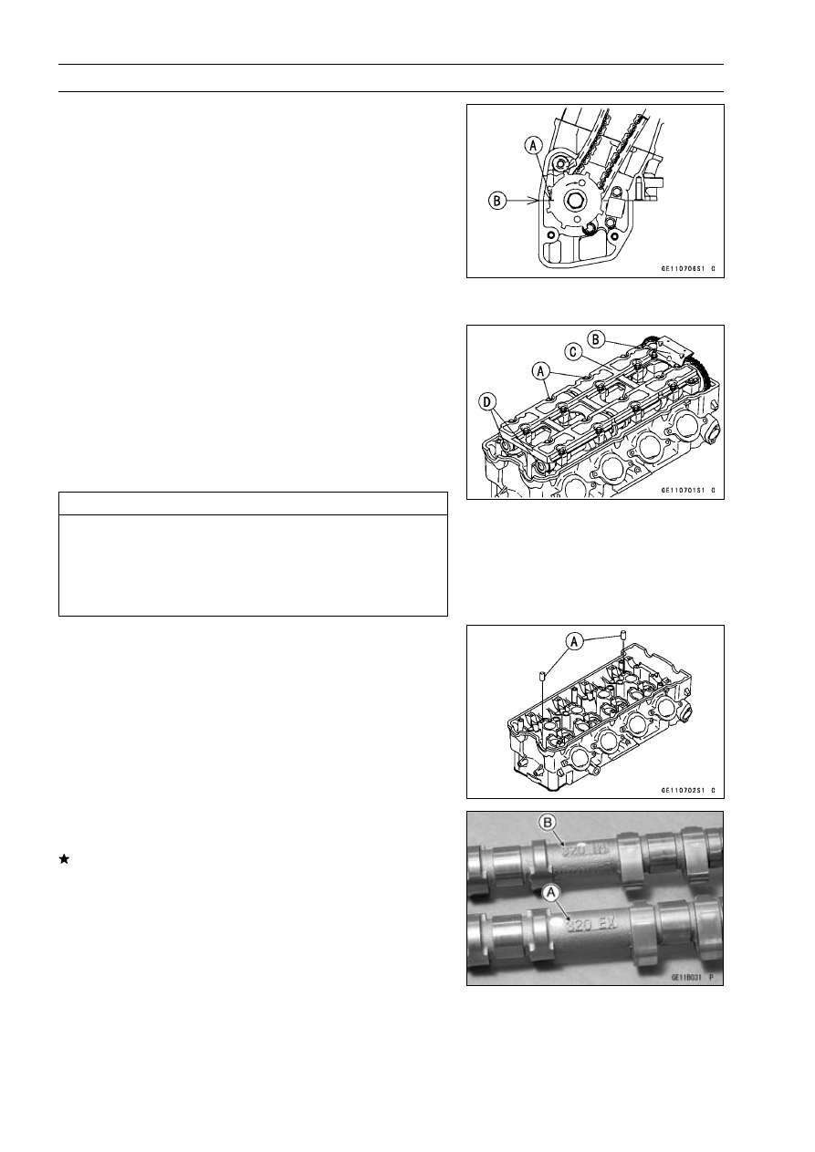
Position the crankshaft at #1, #4 piston TDC.

TDC Mark [A] for #1, #4 Pistons
Timing Mark [B] (crankcase halves mating surface)

Remove:

Camshaft Chain Tensioner (see Camshaft Chain Ten-
sioner Removal)
Camshaft Cap Bolts [A]
Upper Camshaft Chain Guide [B]
Camshaft Cap [C]
Camshafts [D]

Stuff a clean cloth into the chain tunnel to keep any parts
from dropping into the crankcase.

CAUTION

The crankshaft may be turned while the camshafts
are removed. Always pull the chain taut while turn-
ing the crankshaft. This avoids kinking the chain
on the lower (crankshaft) sprocket. A kinked chain
could damage both the chain and the sprocket.

Camshaft Installation

Be sure to install the following parts.

Pins [A]

Apply molybdenum disulfide oil solution to all cam parts
and journals.
If a new camshaft is to be used, apply molybdenum disul-
fide grease to the cam surfaces.

NOTE

The exhaust camshaft has a 320 EX mark [A] and the
inlet camshaft has a 320 IN mark [B]. Be careful not to
mix up these shafts.

ENGINE TOP END 5-15

Camshaft, Camshaft Chain

If the camshaft position sensor rotor is removed, install it
as follows.

Insert the pin [A] into the holes [B] in the camshaft and
boss [C].

Fit the projection [A] of the rotor on the camshaft recess
[B].

Apply a non-permanent locking agent to the camshaft po-
sition sensor rotor bolt [C], and tighten it.

Torque - Camshaft Position Sensor Rotor Bolt: 12 N·m (1.2

kgf·m, 106 in·lb)

Position the crankshaft at #1, #4 piston TDC.

Pull the tension side (exhaust side) [A] of the chain taut
to install the chain

Engage the camshaft chain with the camshaft sprockets
so that the timing marks on the sprockets are positioned
as shown.

The timing mark [B] of #1, #4 T must be aligned with the
mating surface [C] of crankcase of rear side.

The timing marks must be aligned with the cylinder head
upper surface [D].

EX mark [E]
IN mark [F]
#1 Pin [G]
#31 Pin [H]
#32 Pin [I]

5-16 ENGINE TOP END

Camshaft, Camshaft Chain

Install the camshaft cap [A] and upper camshaft chain
guide [B]. While pushing the camshaft chain, tighten all
camshaft bolts and chain guide bolts.

Install the longer bolts to the #10 and #14 position shown
by triangle marks.

First tighten the all camshaft cap and chain guide bolts
evenly to seat the camshaft in place, then tighten all bolts
following the specified tightening sequence.

Torque - Camshaft Cap Bolts: 12 N·m (1.2 kgf·m, 106 in·lb)

Upper Camshaft Chain Guide Bolts: 12 N·m (1.2

kgf·m, 106 in·lb)

Install the camshaft chain tensioner (see Camshaft Chain
Tensioner Installation).

Install the cylinder head cover (see Cylinder Head Cover
Installation).

Camshaft, Camshaft Cap Wear

Cut strips of plastigage (press gauge) to journal width.
Place a strip on each journal parallel to the camshaft in-
stalled in the correct position.

Measure each clearance between the camshaft journal
and the camshaft cap using plastigage [A].

Tighten:

Torque - Camshaft Cap Bolts: 12 N·m (1.2 kgf·m, 106 in·lb)

Upper Camshaft Chain Guide Bolts: 12 N·m (1.2

kgf·m, 106 in·lb)

NOTE

Do not turn the camshaft when the plastigage is be-
tween the journal and camshaft cap.

Camshaft Journal, Camshaft Cap Clearance

Standard:

0.028

0.071 mm (0.0011

0.0028 in.)

Service Limit:

0.16 mm (0.006 in.)

If any clearance exceeds the service limit, measure the
diameter of each camshaft journal with a micrometer.

Camshaft Journal Diameter

Standard:

23.950

23.972 mm (0.9429

0.9438 in.)

Service Limit: 23.92 mm (0.942 in.)

If the camshaft journal diameter is less than the service
limit, replace the camshaft with a new one and measure
the clearance again
If the clearance still remains out of the limit, replace the
cylinder head with camshaft cap.

ENGINE TOP END 5-17

Camshaft, Camshaft Chain

Camshaft Runout

Remove the camshaft (see Camshaft Removal).

Set the camshaft in a camshaft alignment jig or on V
blocks.

Measure runout with a dial gauge at the specified place
as shown.
If the runout exceeds the service limit, replace the
camshaft.

Camshaft Runout

Standard:

TIR 0.02 mm (0.0008 in.) or less

Service Limit: TIR 0.1 mm (0.004 in.)

Cam Wear

Remove the camshaft (see Camshaft Removal).

Measure the height [A] of each cam with a micrometer.
If the cams are worn down past the service limit, replace
the camshaft.

Cam Height

Standard:

Exhaust

36.643

36.757 mm (1.4426

1.4471 in.)

Inlet

37.043

37.157 mm (1.4584

1.4629 in.)

Service Limit:

Exhaust

36.54 mm (1.439 in.)

Inlet

36.94 mm (1.454 in.)

Camshaft Chain Removal

Split the crankcase (see Crankshaft/Transmission chap-
ter).

Remove the camshaft chain [A] from the crankshaft
sprocket.

5-18 ENGINE TOP END

Cylinder Head

Cylinder Compression Measurement

NOTE

Use the battery which is fully charged.

Warm up the engine thoroughly.

Stop the engine.

Remove:

Lower Inner Covers (see Frame chapter)
Baffle Plate (see Cylinder Head Cover Removal)
Stick Coils (see Electrical System chapter)
Spark Plugs (see Electrical System chapter)

Attach the compression gauge [A] and adapter [B] firmly
into the spark plug hole.

Using the starter motor, turn the engine with the throttle
fully open until the compression gauge stops rising; the
compression is the highest reading obtainable.

Special Tools - Compression Gauge: 57001-221

Compression Gauge Adapter, M10 × 1.0:

57001-1458

Cylinder Compression

Usable Range:

1 029

1 568 kPa (10.5

16 kgf/cm²,

149

228 psi) @300 r/min (rpm)

Repeat the measurement for the other cylinders.

Install the spark plugs.

Torque - Spark Plugs: 13 N·m (1.3 kgf·m, 115 in·lb)

The following table should be consulted if the obtainable compression reading is not within the us-

able range.

Problem

Diagnosis

Remedy (Action)

Carbon accumulation on piston and
in combustion chamber possibly
due to damaged valve stem oil seal
and/or damaged piston oil rings (This
may be indicated by white exhaust
smoke)

Remove the carbon deposits
and replace damaged parts if
necessary.

Cylinder compression
is higher than usable
range

Incorrect cylinder head gasket
thickness.

Replace the gasket with a standard
part.

Gas leakage around cylinder head

Replace damaged gasket and
check cylinder head warp.

Bad condition of valve seating

Repair if necessary.

Cylinder compression is
lower than usable range

Incorrect valve clearance

Adjust the valve clearance.

Incorrect piston/cylinder clearance

Replace the piston and/or cylinder.

Piston seizure

Inspect the cylinder and
replace/repair the cylinder and/or
piston as necessary.

Bad condition of piston ring and/or
piston ring grooves

Replace the piston and/or the
piston rings.

ENGINE TOP END 5-19

Cylinder Head

Cylinder Head Removal

Drain the coolant (see Coolant Change in the Periodic
Maintenance chapter).

Remove:

Radiator (see Cooling System chapter)
Muffler (see Muffler Removal)
Clutch Cable Lower End (see Clutch chapter)
Engine Mounting Bolts [C]
Engine Bracket Bolts [A]
Engine Brackets [B]
Throttle Body Assy (see Fuel System (DFI) chapter)
Cylinder Head Cover (see Cylinder Head Cover Re-
moval)
Camshaft Position Sensor (see Electrical System chap-
ter)
Camshaft Chain Tensioner (see Camshaft Chain Ten-
sioner Removal)
Camshafts (see Camshaft Removal)

Remove:

Cooling Hose [A]

Remove:

Camshaft Chain Guide Bolts [A]
Front and Rear Camshaft Chain Guides

Pull up the camshaft chain guides from the cylinder head
with plieres.

Remove the M7 cylinder head bolts [A], and then the M11
cylinder head bolts [B].

Take off the cylinder head.

5-20 ENGINE TOP END

Cylinder Head

Cylinder Head Installation

NOTE

The camshaft cap is machined with the cylinder head,
so if a new cylinder head is installed, use the cap that
is supplied with the new head.

Make sure that the O-ring [A] of the oil pipe is not damage,
and apply high-temperature grease to it.

Verify that the oil pipe [B] is installed properly.

Install a new cylinder head gasket [C], and knock pins [D].

Apply molybdenum disulfide oil solution to both sides [A]
of the cylinder head bolt washers [B] and the thread of
head bolts [C].

Tighten the M11 cylinder head bolts following the tighten-
ing sequence [1

10].

Torque - Cylinder Head Bolts (M11):

First: 23 N·m (2.3 kgf·m, 17 ft·lb)
Final: 59 N·m (6.0 kgf·m, 44 ft·lb)

Tighten the M7 cylinder head bolts [11

12].

Torque - Cylinder Head Bolts (M7): 20 N·m (2.0 kgf·m, 15

ft·lb)

Install:

Front Camshaft Chain Guide [A]
O-ring [B]
Collar [C]

Tighten:

Torque - Front Camshaft Chain Guide Bolt (Upper) [D]:

25 N·m (2.5 kgf·m, 18 ft·lb)

Front Camshaft Chain Guide Bolt (Lower) [E]:

12 N·m (1.2 kgf·m, 106 in·lb)

Install:

Rear Camshaft Chain Guide [F]

Tighten:

Torque - Rear Camshaft Chain Guide Bolt [G]:

25 N·m (2.5 kgf·m, 18 ft·lb)

Install the camshafts (see Camshaft Installation).

ENGINE TOP END 5-21

Cylinder Head

Cylinder Head Warp

Clean the cylinder head.

Lay a straightedge across the lower surface of the cylinder
head at several positions.

Measure the space between the straightedge [B] and the
head with a thickness gauge [A].

Cylinder Head Warp

Standard:

– – –

Service Limit:

0.05 mm (0.002 in.)

If the cylinder head is warped more than the service limit,
replace it.
If the cylinder head is warped less than the service limit,
repair the head by rubbing the lower surface on emery
paper secured to a surface plate (first No. 200, then No.
400).

5-22 ENGINE TOP END

Valves

Valve Clearance Check

Refer to the Valve Clearance Inspection and Adjustment
in the Periodic Maintenance chapter (2nd chapter).

Valve Removal

Remove the cylinder head (see Cylinder Head Removal).

Remove the valve lifter and shim.

Mark and record the valve lifter and shim locations so they
can be installed in their original positions.

Using the valve spring compressor assembly, remove the
valve.

Special Tools - Valve Spring Compressor Assembly: 57001

-241 [A]

Adapter, 22: 57001-1202 [B]

Valve Installation

Replace the oil seal with a new one.

Apply thin coat of molybdenum disulfide grease to the
valve stem before valve installation.

Install the springs so that the closed coil end faces down-
wards.

Valve Spring Paint Color:

EX - Red
IN - Blue

Valve Stem [A]
Oil Seal [B]
Spring Seat [C]
Closed Coil End [D]
Valve Springs (Inner) [E]
Valve Springs (Outer) [F]
Retainer [G]
Split Keepers [H]

Valve Guide Removal

Remove:

Valve (see Valve Removal)
Oil Seal
Spring Seat

Heat the area around the valve guide to 120

150°C (248

302°F), and hammer lightly on the valve guide arbor [A]

to remove the guide from the top of the head.

CAUTION

Do not heat the cylinder head with a torch. This will
warp the cylinder head. Soak the cylinder head in
oil and heat the oil.

Special Tool - Valve Guide Arbor, 5.0: 57001-1203

ENGINE TOP END 5-23

Valves

Valve Guide Installation

Apply engine oil to the valve guide outer surface before
installation.

Heat the area around the valve guide hole to about 120

150°C (248

302°F).

Drive the valve guide in from the top of the head using the
valve guide arbor. The flange stops the guide from going
in too far.

Special Tool - Valve Guide Arbor, 5.0: 57001-1203

Ream the valve guide with valve guide reamer [A] even if
the old guide is reused.

Special Tool - Valve Guide Reamer, 5.0: 57001-1204

Valve-to-Guide Clearance Measurement (Wobble

Method)

If a small bore gauge is not available, inspect the valve

guide wear by measuring the valve to valve guide clearance
with the wobble method as indicated below.

Insert a new valve [A] into the guide [B] and set a dial
gauge against the stem perpendicular to it as close as
possible to the cylinder head mating surface.

Move the stem back and forth [C] to measure valve/valve
guide clearance.

Repeat the measurement in a direction at a right angle to
the first.
If the reading exceeds the service limit, replace the guide.

NOTE

The reading is not actual valve/valve guide clearance
because the measuring point is above the guide.

Valve/Valve Guide Clearance (Wobble Method)

Standard:

Exhaust

0.09

0.17 mm (0.0035

0.0067 in.)

Inlet

0.03

0.11 mm (0.0012

0.0043 in.)

Service Limit:

Exhaust

0.35 mm (0.014 in.)

Inlet

0.29 mm (0.011 in.)

5-24 ENGINE TOP END

Valves

Valve Seat Inspection

Remove the valve (see Valve Removal).

Check the valve seating surface [A] between the valve [B]
and valve seat [C].

Measure the outside diameter [D] of the seating pattern
on the valve seat.
If the outside diameter is too large or too small, repair the
seat (see Seat Repair).

Valve Seating Surface Outside Diameter

Standard:

Exhaust

27.6

27.8 mm (1.086

1.094 in.)

Inlet

32.6

32.8 mm (1.283

1.291 in.)

Measure the seat width [E] of the portion where there is
no build-up carbon (white portion) of the valve seat with a
vernier caliper.

Good [F]

If the width is too wide [G], too narrow [H] or uneven [J],
repair the seat (see Valve Seat Repair).

Valve Seating Surface Width

Standard:

Exhaust

0.8

1.2 mm (0.03

0.047 in.)

Inlet

0.5

1.0 mm (0.02

0.039 in.)

Valve Seat Repair

Repair the valve seat with the valve seat cutters [A].

Special Tools - Valve Seat Cutter Holder Bar: 57001-1128

[C]

Valve Seat Cutter Holder, 5.0: 57001-1208

[B]

[For Exhaust Valve Seat]

Valve Seat Cutter, 45° - 30: 57001-1187
Valve Seat Cutter, 32° - 30: 57001-1120
Valve Seat Cutter, 60° - 30: 57001-1123

[For Inlet Valve Seat]

Valve Seat Cutter, 45° - 35: 57001-1116
Valve Seat Cutter, 32° - 35: 57001-1121
Valve Seat Cutter, 55° - 35: 57001-1247

If the manufacturer’s instructions are not available, use
the following procedure.

ENGINE TOP END 5-25

Valves

Seat Cutter Operation Care

1. This valve seat cutter is developed to grind the valve for

repair. Therefore the cutter must not be used for other
purposes than seat repair.

2. Do not drop or shock the valve seat cutter, or the dia-

mond particles may fall off.

3. Do not fail to apply engine oil to the valve seat cutter

before grinding the seat surface. Also wash off ground
particles sticking to the cutter with washing oil.

NOTE

Do not use a wire brush to remove the metal particles
from the cutter. It will take off the diamond particles.

4. Setting the valve seat cutter holder in position, operate

the cutter in one hand. Do not apply too much force to
the diamond portion.

NOTE

Prior to grinding, apply engine oil to the cutter and dur-
ing the operation, wash off any ground particles sticking
to the cutter with washing oil.

5. After use, wash it with washing oil and apply thin layer

of engine oil before storing.

Marks Stamped on the Cutter

The marks stamped on the back of the cutter [A] represent

the following.
60° ........................... Cutter angle [B]

37.5 ....................... Outer diameter of cutter [C]

Operating Procedures

Clean the seat area carefully.

Coat the seat with machinist’s dye.

Fit a 45° cutter into the holder and slide it into the valve
guide.

Press down lightly on the handle and turn it right or left.
Grind the seating surface only until it is smooth.

CAUTION

Do not grind the seat too much. Overgrinding will
reduce valve clearance by sinking the valve into the
head. If the valve sinks too far into the head, it will
be impossible to adjust the clearance, and the cylin-
der head must be replaced.

5-26 ENGINE TOP END

Valves

Measure the outside diameter of the seating surface with
a vernier caliper.
If the outside diameter of the seating surface is too small,
repeat the 45° grind until the diameter is within the spec-
ified range.

Widened Width [A] of engagement by machining with
45° cutter
Ground Volume [B] by 32° cutter
32° [C]
Correct Width [D]
Ground Volume [E] by 60° or 55° cutter
60° or 55° [F]

Measure the outside diameter of the seating surface with
a vernier caliper.
If the outside diameter of the seating surface is too small,
repeat the 45° grind [A] until the diameter is within the
specified range.

Original Seating Surface [B]

NOTE

Remove all pittings of flaws from 45° ground surface.

After grinding with 45° cutter, apply thin coat of machin-
ist’s dye to seating surface. This makes seating surface
distinct and 32° and 60° grinding operation easier.

When the valve guide is replaced, be sure to grind with
45° cutter for centering and good contact.

If the outside diameter [A] of the seating surface is too
large, make the 32° grind described below.
If the outside diameter of the seating surface is within the
specified range, measure the seat width as described be-
low.

Grind the seat at a 32° angle [B] until the seat O.D. is
within the specified range.

To make the 32° grind, fit a 32° cutter into the holder, and
slide it into the valve guide.

Turn the holder one turn at a time while pressing down
very lightly. Check the seat after each turn.

CAUTION

The 32° cutter removes material very quickly.
Check the seat outside diameter frequently to pre-
vent overgrinding.

After making the 32° grind, return to the seat O.D. mea-
surement step above.

To measure the seat width, use a vernier caliper to mea-
sure the width of the 45° angle portion of the seat at sev-
eral places around the seat.
If the seat width is too narrow, repeat the 45° grind until
the seat is slightly too wide, and then return to the seat
O.D. measurement step above.

ENGINE TOP END 5-27

Valves

If the seat width is too wide, make the 60° or 55° [A] grind
described below.
If the seat width is within the specified range, lap the valve
to the seat as described below.

Grind the seat at a 60° or 55° angle until the seat width is
within the specified range.

To make the 60° or 55° grind, fit 60° or 55° cutter into the
holder, and slide it into the valve guide.

Turn the holder, while pressing down lightly.

After making the 60° or 55° grind, return to the seat width
measurement step above.

Correct Width [B]

Lap the valve to the seat, once the seat width and O.D.
are within the ranges specified above.

Put a little coarse grinding compound on the face of the
valve in a number of places around the valve head.

Spin the valve against the seat until the grinding com-
pound produces a smooth, matched surface on both the
seat and the valve.

Repeat the process with a fine grinding compound.

Lapper [A]
Valve Seat [B]
Valve [C]

The seating area should be marked about in the middle
of the valve face.
If the seat area is not in the right place on the valve, check
to be sure the valve is the correct part. If it is, it may have
been refused too much; replace it.

Be sure to remove all grinding compound before assem-
bly.

When the engine is assembled, be sure to adjust the valve
clearance (see Valve Clearance Adjustment section of
Periodic Maintenance chapter).

5-28 ENGINE TOP END

Valves

ENGINE TOP END 5-29

Cylinder, Pistons

Cylinder Removal

Remove:

Cylinder Head (see Cylinder Head Removal)
Cooling Hoses [A]
Oil Pipe [B]

Remove the cylinder [C].

Cylinder Installation

NOTE

If a new cylinder is used, use new piston rings.

If new pistons and/or a new cylinder are installed, apply
thin coat of molybdenum disulfide grease to the new
pistons and cylinder bores.

Replace the cylinder gasket with a new one, and install
the pins [A] and new cylinder gasket.

Apply molybdenum disulfide oil solution to the cylinder
bore, external of pistons and piston rings.

The piston ring openings must be positioned as shown in
the figure. The openings of the oil ring steel rails must be
about 30

40° of angle from the opening of the top ring.

Top Ring [A]
Second Ring [B]
Oil Ring Steel Rails [C]
Oil Ring Expander [D]
Hollow [E]

Insert the piston in the cylinder by two methods.

With the Hand

Position the crankshaft at #2, #3 piston TDC.

Install the two cylinder head bolts [A] diagonally in the
crankcase.

Install the cylinder block [B].

Pistons [C]

First insert the #2, #3 pistons, and then rotate the crank-
shaft at 90° angle.

Insert the piston rings with your thumbs or the thin (–)
screw driver.

5-30 ENGINE TOP END

Cylinder, Pistons

With the Special Tools

Install the two cylinder head bolts [A] diagonally in the
crankcase.

Slip the piston bases [B] under the pistons to hold them
level.

Compress the piston rings using the piston ring compres-
sor grips [C] and piston ring compressor belts [D] with
chamfered side upward.

Special Tools - Piston Ring Compressor Grip: 57001-1095

Piston Ring Compressor Belt,

80

91:

57001-1320

Piston Base, 1.0: 57001-1459

Push down vigorously the cylinder aligning the cylinder
bores with all the piston heads.

Install the cylinder [A] so that its angle aligns the piston
angle after removing the piston ring compressor belts.

Piston Removal

Remove the cylinder (see Cylinder Removal).

Place a clean cloth under the pistons and remove the pis-
ton pin snap ring [A] from the outside of each piston.

CAUTION

Do not reuse the snap rings, as removal weakens
deforms then. They fall out and score the cylinder
wall.

Remove the piston pins with a piston pin puller [A].

Special Tool - Piston Pin Puller Assembly: 57001-910

Remove the pistons.

ENGINE TOP END 5-31

Cylinder, Pistons

Carefully spread the ring opening with your thumbs and
then push up on the opposite side of the ring [A] to remove
it.

Remove the 3-piece oil ring with your thumbs in the same
manner.

Piston Installation

Apply molybdenum disulfide oil solution to the oil ring ex-
pander, and install the oil ring expander [A] in the bottom
piston ring groove so the ends [B] butt together.

Apply molybdenum disulfide oil solution to the oil ring steel
rails, and install the oil ring steel rails, one above the ex-
pander and one below it.

Spread the rail with your thumbs, but only enough to fit
the rail over the piston.

Release the rail into the bottom piston ring groove.

NOTE

The oil ring rails have no “top” or “bottom”.

Do not mix up the top and second ring.

Install the top ring [A] so that the "R" mark [B] faces up.

Install the second ring [C] so that the "RN" mark [D] faces
up.

Apply molybdenum disulfide oil solution to the piston
rings.

NOTE

If a new piston is used, use new piston ring.

Install the piston with its marking hollow facing forward.

Fit a new piston pin snap ring into the side of the piston
so that the ring opening [A] does not coincide with the slit
[B] of the piston pin hole.

Apply molybdenum disulfide oil solution to the piston pins
and piston journals.

When installing the piston pin snap ring, compress it only
enough to install it and no more.

CAUTION

Do not reuse snap rings, as removal weakens and
deforms them.
They could fall out and score the cylinder wall.

Install the cylinder (see Cylinder Installation).

5-32 ENGINE TOP END

Cylinder, Pistons

Cylinder Wear

Since there is a difference in cylinder wear in different di-
rections, take a side-to-side and a front-to-back measure-
ment at each of the two locations (total of four measure-
ments) shown in the figure.
If any of the cylinder inside diameter measurements ex-
ceeds the service limit, replace the cylinder.

10 mm (0.39 in.) [A]
60 mm (2.36 in.) [B]

Cylinder Inside Diameter

Standard:

82.994

83.006 mm (3.2675

3.2679

in.)

Service Limit:

83.06 mm (3.270 in.)

Piston Wear

Measure the outside diameter [A] of each piston 18 mm
(0.71 in.) [B] up from the bottom of the piston at a right
angle to the direction of the piston pin
If the measurement is under service limit, replace the pis-
ton.

Piston Diameter

Standard:

82.969

82.984 mm (3.2665

3.2671

in.)

Service Limit:

82.82 mm (3.261 in.)

Piston Ring, Piston Ring Groove Wear

Check for uneven groove wear by inspecting the ring seat-
ing.
The rings should fit perfectly parallel to groove surfaces.
If not, replace the piston and all the piston rings.

With the piston rings in their grooves, make several mea-
surements with a thickness gauge [A] to determine piston
ring/groove clearance.

Piston Ring/Groove Clearance

Standard:

Top

0.03

0.07 mm (0.0012

0.0028 in.)

Second

0.02

0.06 mm (0.0008

0.002 in.)

Service Limit:

Top

0.17 mm (0.0067 in.)

Second

0.16 mm (0.0063 in.)

Piston Ring Groove Width

Measure the piston ring groove width.

Use a vernier caliper at several points around the piston.

Piston Ring Groove Width

Standard:

Top [A]

0.92

0.94 mm (0.0362

0.0370 in.)

Second [B]

1.01

1.03 mm (0.0398

0.0406 in.)

Service Limit:

Top [A]

1.02 mm (0.0402 in.)

Second [B]

1.11 mm (0.0437 in.)

If the width of any of the two grooves is wider than the
service limit at any point, replace the piston.

ENGINE TOP END 5-33

Cylinder, Pistons

Piston Ring Thickness

Measure the piston ring thickness.

Use the micrometer to measure at several points around
the ring.

Piston Ring Thickness

Standard:

Top [A]

0.87

0.89 mm (0.0343

0.0350 in.)

Second [B]

0.97

0.99 mm (0.0382

0.0390 in.)

Service Limit:

Top [A]

0.80 mm (0.0315 in.)

Second [B]

0.90 mm (0.0354 in.)

If any of the measurements is less than the service limit
on either of the rings, replace all the rings.

NOTE

When using new rings in a used piston, check for un-
even groove wear. The rings should fit perfectly parallel
to the groove sides. If not, replace the piston.

Piston Ring End Gap

Place the piston ring [A] inside the cylinder, using the pis-
ton to locate the ring squarely in place. Set it close to the
bottom of the cylinder, where cylinder wear is low.

Measure the gap between the ends of the ring with a thick-
ness gauge [B].

Piston Ring End Gap

Standard:

Top

0.25

0.40 mm (0.0098

0.0157 in.)

Second

0.40

0.55 mm (0.0157

0.0217 in.)

Service Limit:

Top

0.7 mm (0.0276 in.)

Second

0.8 mm (0.0315 in.)

If the end gap of either ring is greater than the service
limit, replace all the rings.

5-34 ENGINE TOP END

Throttle Body Holder

Throttle Body Holder Installation

Install the throttle body holders with the holes [A] upward.

Check to make sure that the O-ring is not damage, and
apply high-temperature grease to it.

Install the clamps [B] as shown.

Tighten the holder bolt.

Torque - Throttle Body Holder Bolts: 12 N·m (1.2 kgf·m, 106

in·lb)

ENGINE TOP END 5-35

Muffler

WARNING

To avoid a serious burn, do not remove the muffler
when the engine is still hot. Wait until the muffler
cools down.

Muffler Removal

Remove:

Lower Fairings with Lower Inner Fairing (see Frame
chapter)
Lower Inner Covers (see Frame chapter)
Air Inlet Ducts (see Fuel System (DFI) chapter)
Radiator (see Cooling System chapter)

Muffler Body Mounting Nut [A]

Remove:

Exhaust Pipe Manifold Holder Nuts [A]

Pull the muffler body mounting bolt and remove the muf-
fler assembly.

Muffler Installation

Replace the exhaust pipe gaskets with new ones.

Thoroughly warm up the engine, wait until the engine
cools down, and retighten all the bolts and nuts.

Muffler Body Removal

Unscrew the muffler body connection cover bolts [A] and
remove the cover [B].

Remove:

Muffler Body Connection Nuts [A]
Muffler Body Mounting Bolt and Nut [B]

Pull the muffler body [C] backward.

5-36 ENGINE TOP END

Muffler

Muffler Body Installation

Replace the exhaust pipe connection gasket [A] with a
new one.

Insert the muffler body to the exhaust pipe end.

Tighten:

Torque - Muffler Body Connection Nuts: 34 N·m (3.5 kgf·m,

25 ft·lb)

Tighten:

Muffler Body Connecting Cover Bolts
Muffler Body Mounting Bolt and Nut

Thoroughly warm up the engine, wait until the engine
cools down, and retighten all the bolts and nuts.

CLUTCH 6-1

6

Clutch

Table of Contents

Exploded View........................................................................................................................

6-2

Specifications .........................................................................................................................

6-3

Clutch Lever and Cable ..........................................................................................................

6-4

Lever Free Play Inspection ...............................................................................................

6-4

Lever Free Play Adjustment..............................................................................................

6-4

Cable Removal .................................................................................................................

6-4

Cable Installation ..............................................................................................................

6-4

Cable Lubrication ..............................................................................................................

6-4

Clutch Lever Installation....................................................................................................

6-4

Clutch Cover...........................................................................................................................

6-5

Clutch Cover Removal ......................................................................................................

6-5

Clutch Cover Installation ...................................................................................................

6-5

Release Shaft Removal ....................................................................................................

6-6

Release Shaft Installation .................................................................................................

6-6

Clutch Cover Disassembly................................................................................................

6-6

Clutch Cover Assembly.....................................................................................................

6-7

Clutch .....................................................................................................................................

6-8

Clutch Removal.................................................................................................................

6-8

Clutch Installation..............................................................................................................

6-9

Clutch Plate Assembly Inspection.....................................................................................

6-11

Clutch Plate Assembly Adjustment ...................................................................................

6-11

Clutch Plate, Wear, Damage Inspection ...........................................................................

6-12

Clutch Plate Warp Inspection............................................................................................

6-12

Clutch Spring Free Length Measurement .........................................................................

6-12

6-2 CLUTCH

Exploded View

T1: 15 N·m (1.5 kgf·m, 11 ft·lb)
T2: 7.0 N·m (0.70 kgf·m, 62 in·lb)
T3: 8.8 N·m (0.90 kgf·m, 78 in·lb)
T4: 135 N·m (14 kgf·m, 100 ft·lb)
T5: 7.8 N·m (0.80 kgf·m, 69 in·lb)

CL: Apply cable lubricant.

EO: Apply engine oil.

G: Apply grease.

L: Apply a non-permanent locking agent.

M: Apply molybdenum disulfide grease.

MO: Apply molybdenum disulfide oil solution.

R: Replacement Parts

S: Follow the specific tightening sequence.

CLUTCH 6-3

Specifications

Item

Standard

Service Limit

Clutch Lever Free Play

2

3 mm (0.08

0.12 in.)

– – –

Clutch

Friction Plate Thickness

3.22

3.38 mm (0.127

0.133 in.)

3.0 mm (0.12 in.)

Friction and Steel Plate Warp

0.15 mm (0.0059 in.) or less

0.3 mm (0.01 in.)

Clutch Plate Assembly Length

56.8

57.6 mm (2.24

2.27 in.)

– – –

Clutch Spring Free Length

73.49 mm (2.893 in.)

68.5 mm (2.70 in.)

Special Tools - Clutch Holder: 57001-1243

Clutch Gear Setting: 57001-1455

Sealant - Kawasaki Bond (Silicone Sealant): 56019-120

6-4 CLUTCH

Clutch Lever and Cable

Lever Free Play Inspection

Refer to the Clutch Adjust Inspection in the Periodic Main-
tenance chapter.

Lever Free Play Adjustment

Refer to the Clutch Adjust Inspection in the Periodic Main-
tenance chapter.

Cable Removal

Remove the right lower inner cover (see Frame chapter).

Slide the dust cover [A] at the clutch cable lower end out
of place.

Loosen the nuts [B], and slide the outer of the clutch cable
to the lower side.

Screw in the adjuster.

Line up the slots [A] in the clutch lever [B] and adjuster
[C], and then free the cable from the lever.

While pushing the stopper [E], turn the adjuster.

Free the clutch inner cable tip from the clutch release
lever.

Push the release lever toward the front of the motorcycle
and tape the release lever to the clutch cover to prevent
the release shaft from falling out.

Pull the clutch cable out of the frame.

Cable Installation

Run the clutch cable correctly (see General Information
chapter).

Adjust the clutch cable (see Clutch Adjust Inspection in
the Periodic Maintenance chapter).

Cable Lubrication

Refer to the General Lubrication in the Periodic Mainte-
nance chapter.

Clutch Lever Installation

Install the clutch lever [A] so that the mating surface [B] of
the switch housing is aligned with the mating surface [C]
of the clutch lever clamp.

Tighten the upper clamp bolt first, and then the lower
clamp bolt. There will be a gap at the lower part of the
clamp after tightening.

Torque - Clutch Lever Clamp Bolts: 7.8 N·m (0.80 kgf·m, 69

in·lb)

CLUTCH 6-5

Clutch Cover

Clutch Cover Removal

Set the motorcycle on its side stand, squeeze the front
brake lever, and hold it with a band [A] to prevent the
motorcycle from running forward.

WARNING

Be sure to hold the front brake when removing the
clutch, or the motorcycle may fall over. It could
cause an accident and injury.

CAUTION

Be sure to hold the front brake when removing the
clutch, or the motorcycle may fall over. The motor-
cycle could be damaged.

Remove:

Right Lower Fairing (see Frame chapter)
Clutch Cover Mounting Bolts [B]
Clutch Cable Bracket [C]
Clutch Cable Lower End [A]

Turn the release lever [B] toward the rear [C] as shown,
and remove the clutch cover [A].

CAUTION

Do not remove the clutch release lever and shaft
assembly unless it is absolutely necessary. If re-
moved, the oil seal replacement may be required.

Clutch Cover Installation

Apply silicone sealant to the area [A] where the mating
surface of the crankcase touches the clutch cover gasket.

Be sure to install the pins [B].

Sealant - Kawasaki Bond (Silicone Sealant): 56019-120

6-6 CLUTCH

Clutch Cover

Replace the cover gasket with a new one.

Apply a non-permanent locking agent to the two cover
bolts [A] only.

Tighten the cover bolts.

Torque - Clutch Cover Bolts: 15 N·m (1.5 kgf·m, 11 ft·lb)

Release Shaft Removal

Remove the clutch cable lower end (see Clutch Cable
Removal).

Turn the release lever [A] toward the right about 45° [B]
and pull the lever and shaft assembly straight out of the
clutch cover.

Release Shaft Installation

Apply oil to the needle bearings in the hole of the clutch
cover.

Apply high-temperature grease to the oil seal lips of the
clutch cover.

Apply molybdenum disulfide grease to the pusher-holding
portion on the release shaft.

Insert the release shaft [A] straight into the upper hole of
the clutch cover.

Spring [B]
Washer [C]

CAUTION

When inserting the release shaft, be careful not to
remove the spring of the oil seal.

Clutch Cover Disassembly

Remove the clutch cover (see Clutch Cover Removal).

Pull out the release shaft (see Release Shaft Removal).

Remove:

Damper Plate Bolts [A]
Damper Plate [B]
Damper

CLUTCH 6-7

Clutch Cover

Remove:

Oil Seal [A]
Needle Bearings [B]

Clutch Cover Assembly

Replace the needle bearings and oil seal with new one.

NOTE

Install the needle bearings so that the manufacturer’s
mark face out.

Install the needle bearings [A] and oil seal [B] position as
shown.

Apply a non-permanent locking agent to the damper plate
bolts and tighten them.

Confirm that the torque to fast tightened bolt.

Torque - Clutch Cover Damper Plate Bolts: 7.0 N·m (0.70

kgf·m, 62 in·lb)

6-8 CLUTCH

Clutch

Clutch Removal

Remove:

Right Lower Fairing (see Frame chapter)
Clutch Cover (see Clutch Cover Removal)
Clutch Spring Bolts [A]
Clutch Springs
Clutch Spring Plate [B] (with thrust bearing, pusher [C]
and washer)

Remove:

Friction Plates [A]
Steel Plates
Springs
Spring Seats

Holding the clutch hub [A], remove the nut [B] and washer
[C]

Special Tool - Clutch Holder: 57001-1243 [D]

Remove:

Clutch Hub

Insert the clutch gear setting [A] to the hole of the clutch
housing.

Position the hole [B] of the clutch housing at the front side
of the engine so that the tip of the gear setting does not
hit the crankcase wall.

Align the teeth of the clutch housing gears by the gear
setting.

Special Tool - Clutch Gear Setting: 57001-1455

Pull out the sleeve [A] from the clutch housing [B], and
remove the housing.

If the sleeve does not pull out easily, insert M4 bolts [C]
into the threaded hole of the sleeve, and pull out the
sleeve.

Remove the thrust washer.

CLUTCH 6-9

Clutch

Clutch Installation

Install the thrust washer [A] by facing its chamfered side
[B] towards the crankcase.

Install the oil pump drive gear [A] on the clutch housing.

Align the teeth of the clutch housing gears by the gear
setting [A].

Install the clutch housing so that the hole position forward
of the engine.

Special Tool - Clutch Gear Setting: 57001-1455

Install:

Clutch Housing
Needle Bearing
Sleeve

Apply engine oil to the needle bearing and the sleeve be-
fore installation.

Install the washer [A] so that the OUT SIDE mark [B] faces
outward.

Replace the clutch hub nut with a new one.

Holding the clutch hub, tighten the clutch hub nut with the
torque wrench [B].

Special Tool - Clutch Holder [A]: 57001-1243

Torque - Clutch Hub Nut: 135 N·m (14 kgf·m, 100 ft·lb)


Content      ..     8      9      10      11     ..