Kawasaki Ninja ZX-12R Motorcycle. Service Manual (2002-2005 year) - page 11
 

  Index      Manuals     Kawasaki Ninja ZX-12R Motorcycle. Service Manual (2002-2005 year)


Search            copyright infringement  


Content      ..     9      10      11      12     ..


Kawasaki Ninja ZX-12R Motorcycle. Service Manual (2002-2005 year) - page 11


6-10 CLUTCH

Clutch

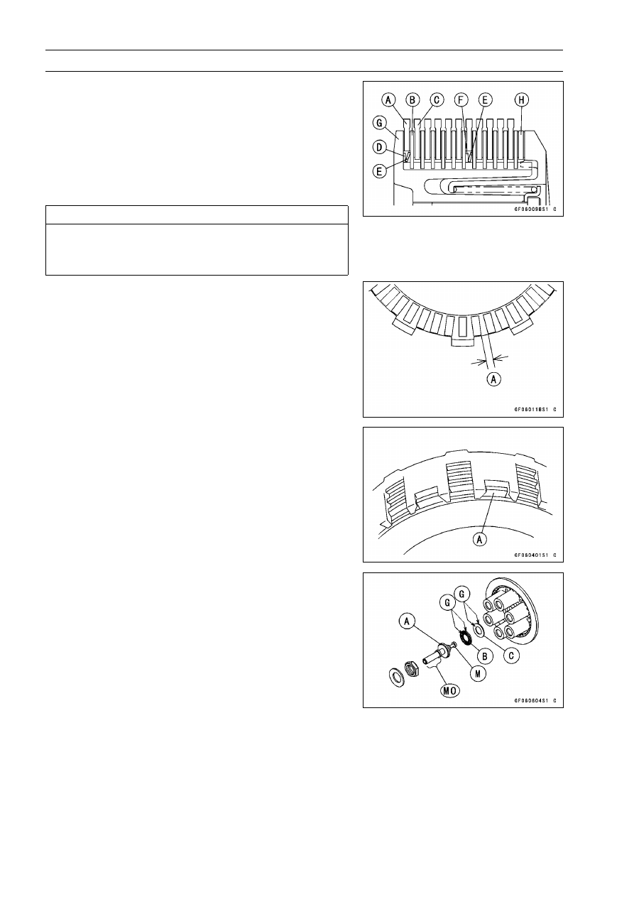
Install the spring seats [D] [F], springs [E], friction plates
[A] [C] [H] and steel plates [B] as shown.

NOTE

The inside diameter of first and seventh friction plates
are larger than the others because the spring seats and
springs are equipped to decrease the judder noise as
shown.

Clutch Hub [G]

CAUTION

If new dry friction plates and steel plates are in-
stalled, apply engine oil to the surfaces of each
plate to avoid clutch plate seizure.

Install outer-end friction plate, that has the narrowest
groove [A] among others.

Install the last friction plate [A] fitting the tangs in the
grooves in the housing as shown.

Apply molybdenum disulfide oil solution [MO] to the out-
side surface of the pusher [A], then install the pusher into
the drive shaft.

Apply high-temperature grease [G] to both side of nee-
dle bearing [B] and washer [C], then install them onto the
pusher.

Apply molybdenum disulfide grease [M] to the mating sur-
face of the pusher.

CLUTCH 6-11

Clutch

Align the mark [A] of the spring plate [B] to one of the
grooves [C] of the clutch hub [D] to install the spring plate
on the clutch hub.

Install the spring, and tighten the clutch spring bolts
evenly.

Torque - Clutch Spring Bolts: 8.8 N·m (0.90 kgf·m, 78 in·lb)

Install the clutch cover (see Clutch Cover Installation).

Clutch Plate Assembly Inspection

Inspect the friction plate thickness (see Clutch Plate,
Wear, Damage Inspection).

Measure the length [A] of the clutch plate assembly as
shown.

Assemble:

Clutch Hub [B]
Spring Seats [C] [K]
Springs [D]
Friction Plates [E] [L] [M]
Steel Plates [F]
Spring Plate [G]
Springs [H]
Spring Seats [I]
Spring Bolts [J]

Torque - Clutch Spring Bolts: 8.8 N·m (0.90 kgf·m, 78 in·lb)

Clutch Plate Assembly Length

Standard:

56.8

57.6 mm (2.24

2.27 in.)

If the length is not within the specified range, adjust the
length (see Clutch Plate Assembly Adjustment).

Clutch Plate Assembly Adjustment

Inspect the clutch plate assembly length, and then re-
place the steel plate(s) which brings the length within the
specified range.

Remove:

Spring Bolts
Springs
Spring Holders
Spring Plate
Clutch Plates

Replace the following steel plate(s).

Part Number

Thickness

13089-1125

1.4 mm (0.055 in.)

13089-1123

1.6 mm (0.063 in.) (Standard)

13089-1124

2.0 mm (0.079 in.)

NOTE

Do not use the steel plate of 2.0 mm (0.079 in.) and 1.4
mm (0.055 in.) thickness at the same time.

Install the removed parts, and inspect the clutch plate as-
sembly length.

Torque - Clutch Spring Bolts: 8.8 N·m (0.90 kgf·m, 78 in·lb)

6-12 CLUTCH

Clutch

Clutch Plate, Wear, Damage Inspection

Visually inspect the friction and steel plates for signs of
seizure, overheating (discoloration), or uneven wear.

Measure the thickness of the friction plate [A] at several
points.
If any plates show signs of damage, or if they have worn
past the service limit, replace them with new ones.

Friction Plate Thickness

Standard:

3.22

3.38 mm (0.127

0.133 in.)

Service Limit:

3.0 mm (0.12 in.)

Clutch Plate Warp Inspection

Place each friction plate or steel plate on a surface plate
and measure the gap between the surface plate [A] and
each friction plate or steel plate [B] with a thickness gauge
[C]. The gap is the amount of friction or steel plate warp.
If any plate is warped over the service limit, replace it with
a new one.

Friction and Steel Plate Warp

Standard:

0.15 mm (0.0059 in.) or less

Service Limit: 0.3 mm (0.01 in.)

Clutch Spring Free Length Measurement

Measure the free length [A] of the clutch springs.
If any spring is shorter than the service limit, it must be
replaced.

Clutch Spring Free Length

Standard:

73.49 mm (2.893 in.)

Service Limit:

68.5 mm (2.70 in.)

ENGINE LUBRICATION SYSTEM 7-1

7

Engine Lubrication System

Table of Contents

Exploded View........................................................................................................................

7-2

Engine Oil Flow Chart.............................................................................................................

7-3

Specifications .........................................................................................................................

7-4

Engine Oil and Oil Filter..........................................................................................................

7-5

Oil Level Inspection...........................................................................................................

7-5

Engine Oil Change............................................................................................................

7-5

Oil Filter Replacement ......................................................................................................

7-5

Oil Cooler................................................................................................................................

7-6

Oil Cooler Removal...........................................................................................................

7-6

Oil Cooler Installation........................................................................................................

7-6

Oil Pan....................................................................................................................................

7-7

Oil Pan Removal ...............................................................................................................

7-7

Oil Pan Installation ............................................................................................................

7-7

Oil Pump, Oil Pump Drive Gear and Oil Pressure Relief Valve..............................................

7-9

Oil Pump Removal ............................................................................................................

7-9

Oil Pump Installation .........................................................................................................

7-9

Oil Pump Inspection..........................................................................................................

7-9

Oil Pump Drive Gear Removal..........................................................................................

7-10

Oil Pump Drive Gear Installation.......................................................................................

7-10

Oil Pressure Relief Valve Inspection.................................................................................

7-10

Oil Pressure Measurement.....................................................................................................

7-12

Oil Pressure Measurement ...............................................................................................

7-12

Oil Pressure Switch ................................................................................................................

7-13

Oil Pressure Switch Removal ...........................................................................................

7-13

Oil Pressure Switch Installation ........................................................................................

7-13

7-2 ENGINE LUBRICATION SYSTEM

Exploded View

T1: 1.5 N·m (0.15 kgf·m, 13 in·lb) or Hand

-Tight

T2: 25 N·m (2.5 kgf·m, 18 ft·lb)
T3: 10 N·m (1.0 kgf·m, 89 in·lb)
T4: 1.5 N·m (0.15 kgf·m, 13 in·lb)
T5: 12 N·m (1.2 kgf·m, 106 in·lb)
T6: 15 N·m (1.5 kgf·m, 11 ft·lb)
T7: 20 N·m (2.0 kgf·m, 15 ft·lb)
T8: 78 N·m (7.8 kgf·m, 58 ft·lb)
T9: 31 N·m (3.2 kgf·m, 23 ft·lb)

EO: Apply engine oil.

G: Apply grease.

L: Apply a non-permanent locking agent.

MO: Apply molybdenum disulfide oil solution.

R: Replacement Parts

SS: Apply silicone sealant.

W: Apply water.

ENGINE LUBRICATION SYSTEM 7-3

Engine Oil Flow Chart

1. Camshaft Oil Passage
2. Oil Pipe
3. Main Oil Passage
4. Crankshaft Oil Passage
5. Oil Filter
6. Oil Cooler
7. Oil Pressure Switch
8. Oil Pipe
9. Oil Pump

10. To Drive Shaft

11. Oil Pipe

12. To Output Shaft

13. Drive Shaft Oil Passage Hole
14. Output Shaft Oil Passage Hole
15. Inlet Camshaft
16. Exhaust Camshaft
17. To Air Cleaner
18. Drive Shaft
19. Relief Valve
20. Oil Screen
21. Oil Drain Plug
22. Output Shaft
23. Stater Clutch

7-4 ENGINE LUBRICATION SYSTEM

Specifications

Item

Standard

Engine Oil

Grade

API SE, SF, or SG
API SH or SJ with JASO MA

Viscosity

SAE 10W-40

Capacity

2.5 L (2.6 US qt, when filter is not removed)
2.8 L (3.0 US qt, when filter is removed)
3.6 L (3.8 US qt, when engine is completely dry)

Level

Between upper and lower level lines

Oil Pressure Measurement

Oil Pressure @4 000 r/min (rpm),
Oil Temperature 90°C (194°F)

196 kPa (2.0 kgf/cm², 28 psi)

Special Tools - Outside Circlip Pliers: 57001-144

Oil Pressure Gauge, 10 kgf/cm²: 57001-164
Oil Pressure Gauge Adapter, PT 1/8: 57001-1033
Oil Filter Wrench: 57001-1249

Sealant - Kawasaki Bond (Silicone Sealant): 56019-120

ENGINE LUBRICATION SYSTEM 7-5

Engine Oil and Oil Filter

WARNING

Motorcycle operation with insufficient, deteri-
orated, or contaminated engine oil will cause
accelerated wear and may result in engine or trans-
mission seizure, accident, and injury.

Oil Level Inspection

Check that the engine oil level is between the upper [A]
and lower [B] levels in the gauge.

Situate the motorcycle so that it is perpendicular to the
ground.

NOTE

If the motorcycle has just been used, wait several min-
utes for all the oil to drain down.

If the oil has just been changed, start the engine and
run it for several minutes at idle speed. This fills the oil
filter with oil. Stop the engine, then wait several minutes
until the oil settles.

CAUTION

Racing the engine before the oil reaches every part
can cause engine seizure.
If the engine oil gets extremely low or if the oil pump
or oil passages clog up or otherwise do not function
properly, the oil pressure warning light will light. If
this light stays on when the engine is running above
idle speed, stop the engine immediately and find the
cause.

If the oil level is too high, remove the excess oil, using a
syring or some other suitable device.
If the oil level is too low, add the correct amount of oil
through the oil filter opening. Use the same type and
make of oil that is already in the engine.

NOTE

If the engine oil type and make are unknown, use any
brand of the specified oil to top off the level in preference
to running the engine with the oil level low. Then at your
earliest convenience, change the oil completely.

Engine Oil Change

Refer to the Engine Oil Change in the Periodic Mainte-
nance chapter.

Oil Filter Replacement

Refer to the Oil Filter Replacement in the Periodic Main-
tenance chapter.

7-6 ENGINE LUBRICATION SYSTEM

Oil Cooler

Oil Cooler Removal

Remove:

Left Lower Fairing (see Frame chapter)

Drain:

Engine Oil (see Engine Oil Change in the Periodic Main-
tenance chapter)
Coolant (see Coolant Change in the Periodic Mainte-
nance chapter)

Loosen the clamp screws [A] and remove the oil cooler
water hoses [B] from the oil cooler.

Remove the oil filter (see Oil Filter Replace in the Periodic
Maintenance chapter).

Unscrew the oil cooler mounting bolts [A] and oil cooler
passage bolt [B] from the crankcase.

Remove the oil cooler.

Drain the coolant and engine oil remaining in the oil cooler
into a suitable container.

Oil Cooler Installation

Installation is the reverse of removal. Note the following.

Apply engine oil to the O-ring [A] before installation.

Apply engine oil to the oil cooler passage bolt.

Apply a non-permanent locking agent to the oil cooler
mounting bolts and install the oil cooler temporarily with
the bolt.

Install the oil cooler mounting bolts evenly.

Tighten the oil cooler passage bolt [A].

Torque - Oil Cooler Passage Bolt: 78 N·m (7.8 kgf·m, 58

ft·lb)

Tighten the oil cooler mounting bolts [B].

Torque - Oil Cooler Mounting Bolts: 25 N·m (2.5 kgf·m, 18

ft·lb)

Install the oil filter (see Oil Filter Replacement in the Pe-
riodic Maintenance chapter).

Pour:

Engine Oil (see Engine Oil Change in the Periodic Main-
tenance chapter)
Coolant (see Coolant Change in the Periodic Mainte-
nance chapter)

ENGINE LUBRICATION SYSTEM 7-7

Oil Pan

Oil Pan Removal

Remove:

Engine Oil (drain, see Engine Oil Change in the Periodic
Maintenance chapter)
Muffler (see Engine Top End chapter)

Unscrew the oil level gauge bolts [A] and pull out the level
gauge [B].

Unscrew the oil pan bolts [C] and remove the oil pan [D].

Remove the oil pipes [A], oil pressure relief valve [B] and
oil screen [C] as necessary.

Oil Pan Installation

Clean the oil screen [A] with high-flash point solvent and
remove any particles stuck to it.

WARNING

Clean the screen in a well-ventilated area, and take
care that there is no spark or flame anywhere near
the working area. Because of the danger of highly
flammable liquids, do not use gasoline or low-flash
point solvents.

NOTE

While cleaning the screen, check for any metal particles
that might indicate internal engine damage.

Check the screen carefully for any damage: hole and
broken wires.

If the screen is damaged, replace it.

Apply grease to the O-ring on the oil screen.

Install the oil screen so that the crankcase rib [A] fits the
slot [B] of the oil screen.

7-8 ENGINE LUBRICATION SYSTEM

Oil Pan

Apply grease to the O-rings on the oil pipes [C].

Apply a non-permanent locking agent to the threads of
the oil pressure relief valve [D], and tighten it.

Torque - Oil Pressure Relief Valve: 15 N·m (1.5 kgf·m, 11

ft·lb)

Replace the oil pan gasket with a new one.

Check that the pins [E] are in place.

Tighten the oil pan bolts.

Install two dowel pins to mark [A], two clamps to mark [B],
and two bolts, shorter than others, to mark [C].

Apply a non-permanent locking agent to the threads of
the bolt [D].

Torque - Oil Pan Bolts: 15 N·m (1.5 kgf·m, 11 ft·lb)

Apply engine oil to the O-rings on the oil level gauge, and
tighten it.

Torque - Oil Level Gauge Bolts: 12 N·m (1.2 kgf·m, 106

in·lb)

ENGINE LUBRICATION SYSTEM 7-9

Oil Pump, Oil Pump Drive Gear and Oil Pressure Relief Valve

Oil Pump Removal

Drain:

Engine Oil (see Engine Oil Change in the Periodic Main-
tenance chapter)
Coolant (see Coolant Change in the Periodic Mainte-
nance chapter)

Remove:

Left Lower Fairing (see Frame chapter)
Water Pump Cover (see Cooling System chapter)
Impeller (see Cooling System chapter)
Water Pump Housing (see Cooling System chapter)

Pull out the oil pump cover [A].

Pull out the oil (water) pump shaft [B] with inner rotor.

Remove the outer rotor.

Oil Pump Installation

Assemble the pin [A] , inner rotor [B] onto the oil (water)
pump shaft [C].

Fit the pin into the slot [D] of the inner rotor.

Install the outer rotor [A] into the crankcase.

Apply molybdenum disulfide oil solution to the journal po-
tions (3 places) on the shaft.

Insert the shaft assembly [B].

Turn the pump shaft so that the slot [C] on its shaft fits
onto the projection [D] of the pump drive gear shaft.

Fit the oil pump cover [B] aligning its hole [C] to the pin
[A] installed on the crankcase.

Install:

Water Pump Housing (see Cooling System chapter)
Impeller (see Cooling System chapter)
Water Pump Cover (see Cooling System chapter)

Oil Pump Inspection

Remove the oil pump parts.

Visually inspect the oil pump outer and inner rotors and
cover.
If there is any damage or uneven wear, replace the rotors
and cover.

7-10 ENGINE LUBRICATION SYSTEM

Oil Pump, Oil Pump Drive Gear and Oil Pressure Relief Valve

Oil Pump Drive Gear Removal

Remove:

Clutch (see Clutch chapter)
Oil Pan (see Oil Pan Removal)
Circlip [A] and Washer [B]

Special Tool - Outside Circlip Pliers: 57001-144

Pull the oil pump drive gear [A] outside.

Oil Pump Drive Gear Installation

Apply molybdenum disulfide oil solution to the journal po-
tion on the oil pump gear shaft.

Install the circlip [A] into the groove [B] of the oil pump
drive gear shaft.

Special Tool - Outside Circlip Pliers: 57001-144

Oil Pressure Relief Valve Inspection

Remove:

Oil Pan (see Oil Pan Removal)
Relief Valve [A]

ENGINE LUBRICATION SYSTEM 7-11

Oil Pump, Oil Pump Drive Gear and Oil Pressure Relief Valve

Check to see if the valve [A] slides smoothly when push-
ing it in with a wooden or other soft rod, and see if it comes
back to its seat by spring [B] pressure.

NOTE

Inspect the valve in its assembled state. Disassembly
and assembly may change the valve performance.

If any rough spots are found during above inspection,
wash the valve clean with a high-flash point solvent and
blow out any foreign particles that may be in the valve with
compressed air.

WARNING

Clean the relief valve in a well-ventilated area, and
take care that there is no spark or flame anywhere
near the working area. Because of the danger of
highly flammable liquids, do not use gasoline or low
-flash point solvent.

If cleaning does not solve the problem, replace the relief
valve as an assembly. The relief valve is precision made
with no allowance for replacement of individual parts.

7-12 ENGINE LUBRICATION SYSTEM

Oil Pressure Measurement

Oil Pressure Measurement

Remove the lower fairing (see Frame chapter).

Remove the oil pressure switch, and attach the gauge and
adapter to the plug hole.

Special Tools - Oil Pressure Gauge, 10 kgf/cm²: 57001-164

[A]

Oil Pressure Gauge Adapter, PT 1/8: 57001

-1033 [B]

Run the engine at the specified speed, and read the oil
pressure gauge.
If the oil pressure is significantly below the specification,
inspect the oil pump and relief valve.
If the oil pump and relief valve are not at fault, inspect the
rest of the lubrication system.

Oil Pressure

Standard:

196 kPa (2.0 kgf/cm², 28 psi) @4 000 r/min
(rpm), oil temperature 90°C (194°F)

Stop the engine.

Remove the oil pressure gauge and adapter.

WARNING

Take care against burns from hot engine oil that
will drain through the oil passage when the gauge
adapter is removed.

Install the oil pressure switch (see Oil Pressure Switch
Installation).

ENGINE LUBRICATION SYSTEM 7-13

Oil Pressure Switch

Oil Pressure Switch Removal

Remove:

Left Lower Fairing (see Frame chapter)
Engine Oil (drain, see Engine Oil Change in the Periodic
Maintenance chapter)
Switch Cover [A]
Switch Terminal Bolt [B]
Oil Pressure Switch [C]

Oil Pressure Switch Installation

Apply silicone sealant to the threads of the oil pressure
switch and tighten it.

Sealant - Kawasaki Bond (Silicone Sealant): 56019-120

Torque - Oil Pressure Switch: 15 N·m (1.5 kgf·m, 11 ft·lb)

Install the switch lead direction [A] forward and upward.

Tighten the terminal bolt.

Torque - Oil Pressure Switch Terminal Bolt: 1.5 N·m (0.15

kgf·m, 13 in·lb)

Apply high-temperature grease to the terminal.

ENGINE REMOVAL/INSTALLATION 8-1

8

Engine Removal/Installation

Table of Contents

Exploded View........................................................................................................................

8-2

Engine Removal/Installation ...................................................................................................

8-3

Engine Removal................................................................................................................

8-3

Engine Installation.............................................................................................................

8-5

8-2 ENGINE REMOVAL/INSTALLATION

Exploded View

T1: 44 N·m (4.5 kgf·m, 32 ft·lb)
T2: 25 N·m (2.5 kgf·m, 18 ft·lb)
T3: 59 N·m (6.0 kgf·m, 44 ft·lb)

A. Engine Mounting Bracket (ZX1200-B1)

D. Degreece (ZX1200-B4

)

ENGINE REMOVAL/INSTALLATION 8-3

Engine Removal/Installation

Engine Removal

Support the rear part of the swingarm with a stand [A].

Squeeze the brake lever slowly and hold it with band [A].

WARNING

Be sure to hold the front brake when removing the
engine, or the motorcycle may fall over. It could
cause an accident and injury.

CAUTION

Be sure to hold the front brake when removing the
engine, or the motorcycle may fall over. The engine
or the motorcycle could be damage.

Drain:

Engine Oil (see Engine Oil Change in the Periodic Main-
tenance chapter)
Coolant (see Coolant Change in the Periodic Mainte-
nance chapter)

Remove:

Lower Fairings with Lower Inner Fairing (see Frame
chapter)

Set up the fuel tank [A] with the supporting rod [B] (see
Fuel System (DFI) chapter).

CAUTION

Do not insert the supporting rod into the bolt hole,
or the thread of the bolt hole could be damaged.

Turn the ignition switch OFF.

Remove:

Battery Compartment Cover (see Electrical System
chapter)
Battery Ground Cable [A]
Starter Motor Cable [B]
Vehicle-down Sensor/Starter Relay Connector [C]
Gear Position Switch and Engine Sub Harness Connec-
tors [D]
Alternator Lead Connector [E]

CAUTION

Do not disconnect the battery cables or any other
electrical connections when the ignition switch is
ON, as this could damage the ECU. Never reverse
the connections of the battery, as this could dam-
age the ECU.

8-4 ENGINE REMOVAL/INSTALLATION

Engine Removal/Installation

Remove:

Radiator (see Cooling System chapter)
Muffler (see Engine Top End chapter)
Choke Cable Lower End
Throttle Cable Lower Ends
Air Cleaner Caps (see Fuel System (DFI) chapter)
Inlet Ducts [A] (see Fuel System (DFI) chapter)

Remove:

Coolant Reserve Tank (see Cooling System chapter)
Shift Lever End (see Crankshaft /Transmission chapter)
Engine Sprocket Cover (see Final Drive chapter)
Engine Sprocket with Drive Chain (see Final Drive chap-
ter)
Fuel Supply Hose End at Fuel Tank (see Fuel System
(DFI) chapter)
Inlet Air Pressure Sensor [A]
Breather Hose End [B]
Sidestand Switch Lead Connector [C]
Vacuum Hose [I]
Alternator Lead Connector [G] (from Regulator Rectifier)

Run the lead connector between the frame and rear
fender front end pushing the rear fender front downward.

Housing Harness Connectors [H]

For California Model:

Canister Purge Hose

Support the engine with a suitable stand [E].

Put a plank [D] onto the suitable stand for engine balance.

Remove:

Engine Mounting Bracket Upper Bolt [F]
Engine Mounting Nuts [J]

Turn the engine mounting bolts [A] clockwise to make the
gap between the engine (adjusting collar) and frame.

Remove:

Engine Mounting Bolts
Collar
Engine Mounting Brackets [B]

Using the stand [C], take out the engine.

ENGINE REMOVAL/INSTALLATION 8-5

Engine Removal/Installation

Engine Installation

CAUTION

Do not connect the throttle sensor connector to the
inlet air pressure sensor, because the pressure sen-
sor is broken by the opposite electrical connection.

Before the engine installing, install the following parts.

Engine Sub Harness [A]
Gear Position Switch Harness [B]
Alternator Leads [D]

Confirm:

Cooling Hoses [C] Position

Confirm the leads and hoses position as shown.

Clamps [A], [C]
Alternator Lead (Yellow) [B]
Alternator Lead (White) [D]
Gear Position Switch Lead [E]
Engine Sub Harness [F]
Fuel Supply Hose [G]
Tube [H]
Tube [I] (for California Model)

Tighten the adjusting collars [A] fully by hand.

Crankcase [B]

Support the engine with a suitable stand.

Hang the drive chain over the output shaft just before
moving the engine into its final position in the frame.

Insert the lower mounting bolt [A].

Set the collar [B] and insert the upper mounting bolt [C].

NOTE

Before inserting the engine mounting bolts, verify that
the fuel hose and tubes (one tube for California model
only), alternator lead connectors, gear position switch
and engine sub harness connectors are clear an open-
ing between the frame and engine.

8-6 ENGINE REMOVAL/INSTALLATION

Engine Removal/Installation

Install the engine mounting bracket [A] to the engine.

For ZX1200-B4 model;

decrease the engine mounting

bolts [B].

Torque - Engine Mounting Bolts (M8) [B]: 25 N·m (2.5 kgf·m,

18 ft·lb)

Install the engine mounting bracket [C] temporarily.

Engine Mounting Bracket Bolt (M10) [D], [E]

Insert the mounting bolts [A] until they fit in the adjusting
collars [B].

Turn the mounting bolts counterclockwise with specified
torque until the clearance [C] between the crankcase [D]
and frame [E] come to zero mm [F].

Torque - Adjusting Collars: 25 N·m (2.5 kgf·m, 18 ft·lb)

Hold the upper and lower engine mounting bolts with
an Allen wrench, and tighten the nuts [A] with specified
torque.

Torque - Engine Mounting Nuts (M12): 59 N·m (6.0 kgf·m,

44 ft·lb)

Tighten the engine mounting bracket bolts [B] with the
sequence lower and upper.

Engine Mounting Bolts (M8) [C]

Torque - Engine Mounting Bracket Bolt (M10): 44 N·m (4.5

kgf·m, 32 ft·lb)

Install the removed parts (see appropriate chapters).

Adjust:

Throttle Cables (see Fuel System (DFI) chapter)
Choke Cable (see Fuel System (DFI) chapter)
Clutch Cable (see Clutch chapter)
Drive Chain (see Final Drive chapter)

CRANKSHAFT/TRANSMISSION 9-1

9

Crankshaft/Transmission

Table of Contents

Exploded View...................................

9-2

Specifications ....................................

9-4

Crankcase Splitting............................

9-7

Crankcase Splitting ......................

9-7

Crankcase Assembly ...................

9-7

Crankshaft and Connecting Rods......

9-11

Crankshaft Removal ....................

9-11

Crankshaft Installation .................

9-11

Connecting Rod Removal ............

9-11

Connecting Rod Installation .........

9-11

Connecting Rod Bend..................

9-13

Connecting Rod Twist ..................

9-14

Connecting Rod Big End Side

Clearance..................................

9-14

Connecting Rod Big End Bearing

Insert/Crankpin Wear ................

9-14

Crankshaft Main Bearing

Insert/Journal Wear...................

9-16

Crankshaft Side Clearance ..........

9-17

Crankshaft Runout .......................

9-18

Balancer ............................................

9-19

Balancer Removal........................

9-19

Balancer Installation.....................

9-19

Balancer Damper Inspection........

9-20

Starter Motor Clutch and Torque

Limiter .............................................

9-21

Starter Motor Removal/Installa-

tion ............................................

9-21

Starter Motor Clutch Removal......

9-21

Starter Motor Clutch Installation...

9-21

Starter Motor Clutch Disassembly

9-21

Starter Motor Clutch Assembly ....

9-22

Starter Clutch Inspection..............

9-22

Torque Limiter Removal ...............

9-23

Torque Limiter Installation ............

9-23

Transmission .....................................

9-24

Shift Pedal Removal ....................

9-24

Shift Pedal Installation .................

9-24

External Shift Mechanism

Removal ....................................

9-25

External Shift Mechanism

Installation .................................

9-26

External Shift Mechanism

Inspection..................................

9-26

Transmission Shaft Removal .......

9-26

Transmission Shaft Installation ....

9-27

Transmission Disassembly ..........

9-27

Transmission Assembly ...............

9-28

Shift Drum and Fork Removal......

9-30

Shift Drum and Fork Installation...

9-31

Shift Drum Disassembly...............

9-31

Shift Drum Assembly ...................

9-32

Shift Fork Bending .......................

9-32

Shift Fork/Gear Groove Wear ......

9-32

Shift Fork Guide Pin/Drum

Groove Wear.............................

9-32

Gear Dog and Gear Dog Hole

Damage.....................................

9-33

9-2 CRANKSHAFT/TRANSMISSION

Exploded View

1. Clamp (ZX1200-B1/B2)

T1: 5.4 N·m (0.55 kgf·m, 48 in·lb)
T2: 10 N·m (1.0 kgf·m, 89 in·lb)
T3: 12 N·m (1.2 kgf·m, 106 in·lb)
T4: 15 N·m (1.5 kgf·m, 11 ft·lb)
T5: 20 N·m (2.0 kgf·m, 15 ft·lb)
T6: 23 N·m (2.3 kgf·m, 17 ft·lb)
T7: 39 N·m (4.0 kgf·m, 29 ft·lb)

T8: 30 N·m (3.0 kgf·m, 22 ft·lb)
T9: See the text.

T10: 50 N·m (5.0 kgf·m, 37 ft·lb)

T11: 28 N·m (2.8 kgf·m, 21 ft·lb)

T12: 25 N·m (2.5 kgf·m, 18 ft·lb)
T13: 2.5 N·m (0.25 kgf·m, 22 in·lb)
T14: 1.5 N·m (0.15 kgf·m, 13 in·lb)

CRANKSHAFT/TRANSMISSION 9-3

Exploded View

D: Do not apply any grease or oil.

EO: Apply engine oil.

G: Apply grease.

L: Apply a non-permanent locking agent.

LG: Apply liquid gasket (Three Bond 1207B).

M: Apply molybdenum disulfide grease.

MO: Apply molybdenum disulfide oil solution.

R: Replacement Parts

S: Follow the specific tightening sequence.

SS: Apply silicone sealant.

St: Stake the fasteners to prevent loosening.

9-4 CRANKSHAFT/TRANSMISSION

Specifications

Item

Standard

Service Limit

Crankshaft, Connecting Rods

Connecting Rod Bend

– – –

0.2/100 mm

(0.008/3.94 in.)

Connecting Rod Twist

– – –

0.2/100 mm

(0.008/3.94 in.)

Connecting Rod Big End Side Clearance

0.13

0.38 mm

0.58 mm

(0.0051

0.0150 in.)

(0.023 in.)

0.048

0.084 mm

0.10 mm

Connecting Rod Big End Bearing Insert/Crankpin
Clearance

(0.0019

0.0033 in.)

(0.0039 in.)

Crankpin Diameter:

36.984

37.000 mm

36.97 mm

(1.4561

1.4567 in.)

(1.456 in.)

Marking

None

36.984

36.992 mm

– – –

(1.4561

1.4564 in.)

36.993

37.000 mm

– – –

(1.45641

1.4567 in.)

Connecting Rod Big End Bore Diameter:

40.000

40.016 mm

– – –

(1.5748

1.5754 in.)

Marking

None

40.000

40.008 mm

– – –

(1.5748

1.5751 in.)

40.009

40.016 mm

– – –

(1.5752

1.5754 in.)

Connecting Rod Big End Bearing Insert Thickness:

Brown

1.475

1.480 mm

– – –

(0.05807

0.05827 in.)

Black

1.480

1.485 mm

– – –

(0.05827

0.05846 in.)

Blue

1.485

1.490 mm

– – –

(0.05846

0.05866 in.)

Connecting Rod Big End Bearing Insert Selection

Bearing Insert

Con-rod Big End

Bore Diameter

Marking

Crankpin

Diameter

Marking

Size Color

Part Number

None

Brown

92139-1093

None

None

Black

92139-1092

None

Blue

92139-1091

Connecting Rod Bolt Stretch (Usable Range)

New Connecting Rod

0.25

0.34 mm

– – –

(0.0094

0.014 in.)

Used Connecting Rod

0.20

0.32 mm

– – –

(0.0079

0.013 in.)

CRANKSHAFT/TRANSMISSION 9-5

Specifications

Item

Standard

Service Limit

Crankshaft Side Clearance

0.05

0.20 mm

0.40 mm

(0.0020

0.0079 in.)

(0.016 in.)

Crankshaft Runout

TIR 0.03 mm (0.0012 in.)

TIR 0.07 mm

or less

(0.0028 in.)

Crankshaft Main Bearing Insert/Journal Clearance 0.031

0.063 mm

0.07 mm

(0.0012

0.0025 in.)

(0.003 in.)

Crankshaft Main Journal Diameter:

36.984

37.000 mm

36.96 mm

(1.4561

1.4567 in.)

(1.455 in.)

Marking

None

36.984

36.992 mm

– – –

(1.4561

1.4564 in.)

1

36.993

37.000 mm

– – –

(1.45641

1.4567 in.)

Crankcase Main Bearing Bore Diameter:

40.000

40.016 mm

– – –

(1.5748

1.5754 in.)

Marking

40.000

40.008 mm

– – –

(1.5748

1.5751 in.)

None

40.009

40.016 mm

– – –

(1.5752

1.5754 in.)

Crankshaft Main Bearing Insert Thickness:

Brown

1.490

1.494 mm

– – –

(0.05866

0.05882 in.)

Black

1.494

1.498 mm

– – –

(0.05882

0.05898 in.)

Blue

1.498

1.502 mm

– – –

(0.05898

0.05913 in.)

Crankshaft Main Bearing Insert Selection

Bearing Insert*

Crankcase Main

Bearing Bore

Diameter Marking

Crankshaft Main

Journal Diameter

Marking

Size Color

Part Number Journal Nos.

92028-1997

1, 5

1

Brown

92139-1055

3

92139-1052

2, 4

None

92028-1996

1, 5

Black

92139-1054

3

None

1

92139-1051

2, 4

92028-1995

1, 5

None

None

Blue

92139-1053

3

92028-1998

2, 4

*The bearing inserts for Nos. 2, 3 and 4 journals have an oil groove, respectively.

Transmission

Shift Fork Ear Thickness

5.9

6.0 mm

5.8 mm

(0.232

0.236 in.)

(0.228 in.)

9-6 CRANKSHAFT/TRANSMISSION

Specifications

Item

Standard

Service Limit

Gear Shift Fork Groove Width

6.05

6.15 mm

6.25 mm

(0.238

0.242 in.)

(0.246 in.)

Shift Fork Guide Pin Diameter

6.9

7.0 mm

6.8 mm

(0.272

0.276 in.)

(0.268 in.)

Shift Drum Groove Width

7.05

7.20 mm

7.3 mm

(0.278

0.283 in.)

(0.287 in.)

Special Tools - Bearing Puller: 57001-135

Steering Stem Bearing Driver: 57001-137
Outside Circlip Pliers: 57001-144
Bearing Puller Adapter: 57001-317

Sealant - Kawasaki Bond (Silicone Sealant): 56019-120

Kawasaki Bond (Liquid Gasket - Black) TB1215: 92104-1062
Three Bond 1207B

CRANKSHAFT/TRANSMISSION 9-7

Crankcase Splitting

Crankcase Splitting

Remove the engine (see Engine Removal/Installation
chapter).

Set the engine on a clean surface and hold the engine
steady while parts are being removed.

Remove:

Crankshaft Sensor (see Electrical System chapter)
Clutch (see Clutch chapter)
External Shift Mechanism (see External Shift Mecha-
nism Removal)
Starter Motor (see Electrical System chapter)
Oil Pump (see Engine Lubrication System chapter)
Alternator Rotor (see Electrical System chapter)
Oil Filter (see Oil Filter Replace in the Periodic Mainte-
nance chapter)
Oil Cooler (see Engine Lubrication System chapter)

If the crankshaft is to be removed, remove the pistons
(see Engine Top End chapter).

Remove the upper crankcase bolts.

First loosen the M7 bolts.

M7 Bolts [A]
M8 Bolts [B]

Remove the oil pan, relief valve, oil screen and oil pipes
(see Engine Lubrication System chapter).

Remove the lower crankcase bolts.

First loosen the M7 bolts.

M7 Bolts [A]
M8 Bolts [B]
M10 Bolts [C]

Tap lightly around the crankcase mating surface with a
plastic mallet, and split the crankcase. Take care not to
damage the crankcase.

Crankcase Assembly

CAUTION

The upper and lower crankcase halves are ma-
chined at the factory in the assembled state, so the
crankcase halves must be replaced as a set.

With high-flash point solvent, clean off the mating sur-
faces of the crankcases halves and wipe dry.

Using compressed air, blow out the oil passages in the
crankcase halves.

9-8 CRANKSHAFT/TRANSMISSION

Crankcase Splitting

Apply liquid gasket to the breather plate mating surface
[A] 1 to 1.5 mm (0.04 to 0.06 in.) thick, and then install
the breather plate.

Sealant - Three Bond 1207B

Apply a non-permanent locking agent to the threads and
tighten the breather plate mounting bolts [A].

Torque - Breather Plate Bolts: 10 N·m (1.0 kgf·m, 89 in·lb)

Insert the oil pipe [B] completely and tighten the bolt.

Torque - Oil Pipe Holder Bolt: 12 N·m (1.2 kgf·m, 106 in·lb)

Install the breathe hose [A].

Align the white paint marks [B].

Install the clamp so that its head [C] come to the inward.

Install:

Starter Motor Clutch (see Starter Motor Clutch Installa-
tion)
Crankshaft and Connecting Rods [A]
Camshaft Chain [B]
Transmission Shafts and Gears [C]
Dowel Pins [D]
Balancer (see Balancer Installation)
Shift Drum (see Shift Drum and Fork Installation)
Shift Forks and Shift Rods (see Shift Drum and Fork In-
stallation)

Before fitting the lower case on the upper case, check the
following.

Be sure to hang the camshaft chain on the crankshaft.

Check to see that the shift drum and transmission gears
are in the neutral position.

CRANKSHAFT/TRANSMISSION 9-9

Crankcase Splitting

Apply liquid gasket [A] to the mating surface of the lower
crankcase half.

Pile up the gasket [B] to slot portions.

NOTE

Make the application finish within 5 minutes when
the liquid gasket to the mating surface of the lower
crankcase half is applied.

Moreover fit the case and tighten the case bolts just
after finishing the application of the liquid gasket.

Sealant - Three Bond 1207B

CAUTION

Do not apply liquid gasket around the crankshaft
main bearing inserts, and oil passage holes.

Position the crankshaft at #1, 4 position TDC.

Hold the balancer so that the punch mark [A] on the bal-
ancer weight aligns with the projection [B] of the lower
crankcase.

Fit the lower crankcase to the upper crankcase.

Apply molybdenum disulfide oil solution to the seating sur-
face of the M10 bolt heads.

Tighten the lower crankcase bolts.

Following the sequence numbers on the lower crankcase
half, tighten the M10 bolts [1

6] [C].

Torque - Crankcase Bolts (M10): 50 N·m (5.0 kgf·m, 37 ft·lb)

Following the sequence numbers, tighten the M8 bolts [7

10] [B].

Torque - Lower Crankcase Bolts (M8): 23 N·m (2.3 kgf·m,

17 ft·lb)

Tighten the M7 bolts [A].

Torque - Lower Crankcase Bolts (M7): 20 N·m (2.0 kgf·m,

15 ft·lb)

Put the M8 bolts [A], M7 bolts [B], and the M7 bolt with
the washer [C] into the upper crankcase half as shown in
the figure, tighten the M8 bolts first, then the other bolts.

Torque - Upper Crankcase Bolts (M8): 28 N·m (2.8 kgf·m,

21 ft·lb)

Upper Crankcase Bolts (M7): 25 N·m (2.5 kgf·m,

18 ft·lb)


Content      ..     9      10      11      12     ..