Kawasaki Ninja ZX-12R Motorcycle. Service Manual (2002-2005 year) - page 8
 

  Index      Manuals     Kawasaki Ninja ZX-12R Motorcycle. Service Manual (2002-2005 year)


Search            copyright infringement  


Content      ..     6      7      8      9     ..


Kawasaki Ninja ZX-12R Motorcycle. Service Manual (2002-2005 year) - page 8


3-118 FUEL SYSTEM (DFI)

Fuel Injectors (#1, #2, #3, #4: Service Code 41, 42, 43, 44)

For ZX1200-B3 model

; as shown in the figure.

If the reading is out of the range, perform the “Injector Unit
Test”.
If the reading is normal, perform the “Injector Unit Test”
for confirmation.

Injector Unit Test

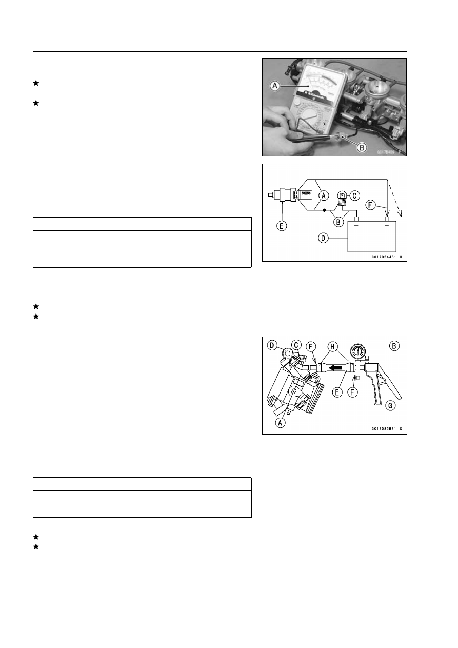
Use two leads [A] and the same test light set [B] as in
“Injector Signal Test”.

Rating of Bulb [C]: 12 V × (3

3.4) W

12 V Battery [D]

CAUTION

Be sure to connect the bulb in series. The bulb
works as a current limiter to protect the solenoid
in the injector from excessive current.

Connect the test light set to the injector [E] as shown.

Open and connect [F] the end of the lead to the battery
(–) terminal repeatedly. The injector should click.
If the injector does not click, replace the throttle body assy.
If the injector clicks, check the wiring again If the wiring is
good, replace the ECU.

Injector Fuel Line Inspection

Remove the throttle body assy (see this chapter).

Check the injector [A] fuel line for leakage as follows:

Connect a commercially available vacuum/pressure
pump [B] to the nipple [C] of the delivery pipe [D] with the
fuel hose [E] (both ends connected with the clamps [H])
as shown.

Apply soap and water solution to the areas [F] shown.

Watching the pressure gauge, squeeze the pump lever
[G], and build up the pressure until the pressure reaches
the maximum pressure.

Fuel Line Maximum Pressure

Standard:

300 kPa (3.06 kgf/cm², 43 psi)

CAUTION

During pressure testing, do not exceed the maxi-
mum pressure for which the system is designed.

Watch the gauge for at least 6 seconds.
If the pressure holds steady, the system is good.
If the pressure drops at once, or if bubbles are found in
the area, the line is leaking. Perform the following as
necessary.

Retighten the fuel hose clamps.

Torque - Fuel Hose Clamp Screws: 1.5 N·m (0.15 kgf·m, 13

in·lb)

FUEL SYSTEM (DFI) 3-119

Fuel Injectors (#1, #2, #3, #4: Service Code 41, 42, 43, 44)

Repeat the leak test, and check the fuel line for no leak-
age.
If again the pressure drops at once, or if bubbles are found
the area, replace the injectors, delivery pipe or related
parts.

Install the throttle body assy (see this chapter).

Run the hoses correctly (see Cable, Wire, and Hose Rout-
ing section in General Information chapter).

Torque - Fuel Hose Clamp Screws: 1.5 N·m (0.15 kgf·m, 13

in·lb)

ZX1200-B1/B2

: Signal

Ignition Switch [17]

ECU Fuse 15 A [27]

ECU [1]

Engine Stop Switch [19]

Starter Motor [29]

Fuel Injector #4 [9]

Junction Box [22]

Starter Relay [30]

Fuel Injector #3 [10]

Ignition Fuse 10 A [23]

Main Fuse 30 A [31]

Fuel Injector #2 [11]

ECU Main Relay [25]

Battery [33]

Fuel Injector #1 [12]

Fuel Pump Relay [26]

3-120 FUEL SYSTEM (DFI)

Fuel Injectors (#1, #2, #3, #4: Service Code 41, 42, 43, 44)

ZX1200-B3

: Signal

Junction Box [22]

Starter Relay [30]

ECU [1]

Ignition Fuse 10 A [23]

Main Fuse 30 A [31]

Fuel Injector #1, #2, #3, #4 [9]

ECU Main Relay [25]

Battery [33]

Ignition Switch [17]

Fuel Pump Relay [26]

Starter Motor [36]

Engine Stop Switch [19]

ECU Fuse 15 A [27]

FUEL SYSTEM (DFI) 3-121

Fuel Pump Relay (Service Code 45, 46)

Service code 45 is short or open to the fuel pump relay

system.

Service code 46 is stuck ON to the fuel pump relay sys-

tem.

Fuel Pump Relay Removal

CAUTION

Never drop the relay, especially on a hard surface.
Such a shock to the relay can damage it.

Remove:

Fuel Tank Cover (see Fuel Tank Removal)
Bracket Bolt [A]

Disconnect the connector and remove the fuel pump relay
[B].

Operating Voltage Inspection

NOTE

Be sure to the battery is fully charged.

Turn the ignition switch OFF.

Remove the ECU (see this chapter). Do not disconnect
the ECU connectors.

Connect the hand tester (× 25 V DC) to the connectors
[A], with the needle adapter set [B].

Special Tools - Hand Tester: 57001-1394

Needle Adapter Set: 57001-1457

Measure the operating voltage with the engine stopped,
and with the connector joined.

Turn the ignition switch ON.

The tester hand does not move for 3 seconds, and then
indicate the battery voltage.

Fuel Pump Relay Operating Voltage at ECU

Connection to ECU

ZX1200-B1/B2:

Tester (+)

BR/Y lead (terminal 8)

Tester (–)

Battery Ground Terminal

ZX1200-B3

:

Tester (+)

BR/Y lead (terminal 56)

Tester (–)

Battery Ground Terminal

Operating Voltage at ECU

Standard:

0 V or 1 V for 3 seconds, and then
battery voltage (12.5 V) or more

3-122 FUEL SYSTEM (DFI)

Fuel Pump Relay (Service Code 45, 46)

If the reading stays on 12.5 V or more, check the following.

[1] Vehicle-down Sensor (see this chapter)
[2] Emergency Engine Stop Voltage
(ZX1200-B1/B2: Terminal 23

←→

Ground)

(ZX1200-B3

: Terminal 53

←→

Ground)

[3] ECU for its Ground, and Power Supply

If the reading stays on 0 V, and never shows, battery volt-
age (12.5 V), check the ECU for its ground and power
supply (see this chapter).
If the ground and power supply are good, replace the
ECU.
If there is no battery voltage at all, check the relay oper-
ating voltage at the relay connector as follows.

Remove the fuel tank cover. Do not disconnect the relay
connector.

Hand Tester [A]
Fuel Pump Relay Connector [B]

Fuel Pump Relay Operating Voltage at Relay Connector

Connection to Relay Connect

Tester (+)

R lead [C]

Tester (–)

Battery (–) Terminal [D]

Operating Voltage at Pump Connector

Standard:

Battery Voltage (12.5 V or more)

If the voltage is in specification, check the relay (see Elec-
trical System chapter) and wiring contiuity.
If the voltage is not specification, check the following.

[1] Ignition Fuse 10 A (see Electrical System chapter)
[2] ECU Fuse 15 A (see this chapter)
[3] Engine Stop Switch (see Electrical System chapter)
[4] ECU Main Relay (see this chapter)
[5] Wiring for Fuel Pump Relay Operating Voltage (see
next diagram)

FUEL SYSTEM (DFI) 3-123

Fuel Pump Relay (Service Code 45, 46)

Power Source Voltage Inspection

NOTE

Confirm that the operation voltage is normal before in-
specting the power source voltage.

Be sure the battery is fully charged.

Connect the hand tester (× 25 V DC) [A] to the connector
[B], with the needle adapter set [C].

Special Tools - Hand Tester: 57001-1394

Needle Adapter Set: 57001-1457

Measure the power source voltage with the engine
stopped, and with the connector joined.

Turn the ignition switch ON.

The tester hand should indicate battery voltage for 3 sec-
onds, and then 0 V.

Relay Power Source Voltage

Connections to ECU

ZX1200-B1/B2:

Tester (+)

W/R lead (terminal 42)

Tester (–)

BK/Y lead (terminal 35)

ZX1200-B3

:

Tester (+)

W/R lead (terminal 33)

Tester (–)

BK/Y lead (terminal 34)

Power Source Voltage at ECU

Standard:

Battery Voltage (12.5 V or more), and
the 0 V

If the power source voltage is less than the standard,
check the ECU for its ground, and power supply (see this
chapter).
If the ground and power supply are good, replace the
ECU.
If the reading stays on battery voltage, and never shows
0 V, recheck the operating voltage or check the fuel pump
relay power source voltage at the relay connector.

Connect the hand tester [A] to the fuel pump relay con-
nector [B].

Measure the power source voltage with the engine
stopped, and with the relay connector joined.

Turn the ignition switch ON.

Fuel Pump Relay Power Source Voltage

Connections to Relay Connector

Tester (+)

W/Y lead [C]

Tester (–)

Battery (–) Terminal [D]

Power Source Voltage at Relay Connector

Standard:

Battery Voltage (12.5 V or more)

3-124 FUEL SYSTEM (DFI)

Fuel Pump Relay (Service Code 45, 46)

If the reading is good, the power source voltage is normal.
Check the fuel pump relay and wiring continuity.
If there is no battery voltage, check the following:

ECU Fuse 15 A (see this chapter)
ECU Main Relay (see this chapter)
Wiring for Fuel Pump Relay Power Source Voltage Sys-
tem

Relay Inspection

Remove the fuel pump relay (see this section).

Refer to the ECU Main Relay Inspection for fuel pump
relay inspection.

Fuel pump relay is identical part the ECU main relay.

ZX1200-B1/B2

: Signal

Junction Box [22]

ECU Fuse 15 A [27]

ECU [1]

Ignition Fuse 10 A [23]

Starter Relay [30]

Ignition Switch [17]

ECU Main Relay [25]

Main Fuse 30 A [31]

Engine Stop Switch [19]

Fuel Pump Relay [26]

Battery [33]

FUEL SYSTEM (DFI) 3-125

Fuel Pump Relay (Service Code 45, 46)

ZX1200-B3

: Signal

Junction Box [22]

ECU Fuse 15 A [27]

ECU [1]

Ignition Fuse 10 A [23]

Starter Relay [30]

Ignition Switch [17]

ECU Main Relay [25]

Main Fuse 30 A [31]

Engine Stop Switch [19]

Fuel Pump Relay [26]

Battery [33]

3-126 FUEL SYSTEM (DFI)

Stick Coils (#1, #2, #3, #4: Service Code 51, 52, 53, 54)

Stick Coil #1: Ignition Coil (Service Code 51)
Stick Coil #2: Ignition Coil (Service Code 52)
Stick Coil #3: Ignition Coil (Service Code 53)
Stick Coil #4: Ignition Coil (Service Code 54)

Removal/Installation

CAUTION

Never drop the ignition coils, especially on a hard
surface. Such a shock to the ignition coil can dam-
age it.

See Ignition System section in the Electrical System
chapter.

Input Voltage Inspection

NOTE

Be sure the battery is fully charged.

Turn the ignition switch OFF.

Remove the ECU (see this chapter). Do not disconnect
the ECU connector.

Connect a digital voltmeter [A] as shown, with the needle
adapter set [B].

Measure the input voltage to each primary winding of the
ignition coils with the engine stopped, and with the con-
nectors joined.

Turn the ignition switch ON.

FUEL SYSTEM (DFI) 3-127

Stick Coils (#1, #2, #3, #4: Service Code 51, 52, 53, 54)

Stick Coil Input Voltage at ECU

ZX1200-B1/B2:

Connections for Stick Coil #1

Meter (+)

BK lead (terminal 1)

Meter (–)

BK/Y lead (terminal 26)

Connections for Stick Coil #2

Meter (+)

BK/G lead (terminal 2)

Meter (–)

BK/Y lead (terminal 26)

Connections for Stick Coil #3

Meter (+)

BK/R lead (terminal 3)

Meter (–)

BK/Y lead (terminal 26)

Connections for Stick Coil #4

Meter (+)

BK/O lead (terminal 10)

Meter (–)

BK/Y lead (terminal 26)

ZX1200-B3

:

Connections for Stick Coil #1

Meter (+)

BK lead (terminal 47)

Meter (–)

BK/Y lead (terminal 59)

Connections for Stick Coil #2

Meter (+)

BK/G lead (terminal 46)

Meter (–)

BK/Y lead (terminal 59)

Connections for Stick Coil #3

Meter (+)

BK/R lead (terminal 45)

Meter (–)

BK/Y lead (terminal 59)

Connections for Stick Coil #4

Meter (+)

BK/O lead (terminal 60)

Meter (–)

BK/Y lead (terminal 59)

Input Voltage at ECU

Standard:

Battery Voltage (12.5 V or more)

If the reading is out of the standard, check the wiring (see
next wiring diagram).
If the reading is good, the input voltage is normal. Crank
the engine, and check the peak voltage of the stick coils
(see Electrical System chapter) in order to check the pri-
mary coils.

3-128 FUEL SYSTEM (DFI)

Stick Coils (#1, #2, #3, #4: Service Code 51, 52, 53, 54)

ZX1200-B1/B2

: Signal

Stick Coil #4 [16]

Ignition Fuse 10 A [23]

ECU [1]

Ignition Switch [17]

Starter Relay [30]

Stick Coil #1 [13]

Engine Stop Switch [19]

Main Fuse 30 A [31]

Stick Coil #2 [14]

Junction Box [22]

Battery [33]

Stick Coil #3 [15]

FUEL SYSTEM (DFI) 3-129

Stick Coils (#1, #2, #3, #4: Service Code 51, 52, 53, 54)

ZX1200-B3

: Signal

Stick Coil #4 [16]

Ignition Fuse 10 A [23]

ECU [1]

Ignition Switch [17]

Starter Relay [30]

Stick Coil #1 [13]

Engine Stop Switch [19]

Main Fuse 30 A [31]

Stick Coil #2 [14]

Junction Box [22]

Battery [33]

Stick Coil #3 [15]

3-130 FUEL SYSTEM (DFI)

Subthrottle Valve Actuator (Service Code 62) (ZX1200-B3

)

Subthrottle Valve Actuator Removal

CAUTION

Do not remove the subthrottle valve actuator [A]
since it has been adjusted and set with precision
at the factory.
Never drop the actuator , especially on a hard sur-
face. Such a shock to the actuator can damage it.

Audible Inspection

NOTE

Be sure the battery is fully charged.

Turn the ignition switch ON and ensure that the actuator
valves open and close (make light sounds) several times
within seconds, and then close at the idle throttle opening
position.

Turn the ignition switch OFF.
If the actuator does not work as described above, do the
visual inspection.

Visual Inspection

Remove the throttle body assy (see Throttle Body Assy
Removal).

Turn the ignition switch ON.

Check to see that all the subthrottle valves [A] open and
close smoothly.
If the subthrottle valves do not operate, check the actuator
internal resistance (see Resistance Inspection).

Resistance Inspection

Turn the ignition switch OFF.

Disconnect the subthrottle valve actuator connector [A].

Connect a digital meter to the subthrottle valve actuator
connector [A].

Measure the subthrottle valve actuator resistance.

Subthrottle Valve Actuator Resistance

Connections:

BK/BL lead [1]

←→

P/BL lead [2]

G lead [3]

←→

W/BL lead [4]

Standard:

about 2

4 k

Special Tool - Hand Tester: 57001-1394

If the reading is out of the range, replace the actuator
along with the throttle body assy.
If the reading is within the range, check the input voltage
(see Input Voltage Inspection).

FUEL SYSTEM (DFI) 3-131

Subthrottle Valve Actuator (Service Code 62) (ZX1200-B3

)

Input Voltage Inspection

NOTE

Be sure the battery is fully charged.

Turn the ignition switch OFF.

Connect the peak voltage adapter [A] and a digital meter
[B] to the connector [C], using the needle adapter set [D].

Special Tool - Peak Voltage Adapter: 57001-1415

Type: KEK-54-9-B

Needle Adapter Set: 57001-1457

Subthrottle Valve Actuator Input Voltage

Connections to Harness Connector
(I)

Meter (+)

BK/BL lead [1]

Meter (–)

P/BL lead [2]

(II)

Meter (+)

G lead [3]

Meter (–)

W/BL lead [4]

Measure the actuator input voltage with the engine
stopped, and with the connector joined.

Turn the ignition switch ON.

Input Voltage at Actuator

Standard:

about 10

14 V DC

If the reading is within the standard but the actuator
doesn’t operate, replace it.
If the reading is out of the range, check the wiring to ECU
(see wiring diagram in this section).
If the wiring is good, check the ECU for its ground and
power supply (see ECU section).

1. ECU

10. Subthrottle Valve Actuator

11. Subthrottle Sensor

A. Throttle Body Assy Connector

3-132 FUEL SYSTEM (DFI)

ECU

CAUTION

Never drop the ECU, especially on a hard surface.
Such a shock to the ECU can damage it.

ECU Removal

Remove:

Rear Seat with Cover (see Frame chapter)
Storage Box (see Frame chapter)

Pull the ECU [A] out.
If necessary, disconnect the connectors [B].

Refer to the Electrical System chapter for Europe model.

ECU Installation

Connect the ECU connectors.
If the rubber protector [A] is removed, install it.

ECU [B]

Insert the projections [A] of the rubber protector into the
holes [B] of the rear fender rear.

ECU Power Supply Inspection

Visually inspect the terminals [A] of the ECU connectors.
If the connector is clogged with mud or dust, blow it off
with compressed air.
Replace the main harness if the terminals of the main
harness connectors are cracked, bent, or otherwise dam-
aged.
Replace the ECU if the terminals of the ECU connectors
are cracked, bent, or otherwise damaged.

FUEL SYSTEM (DFI) 3-133

ECU

With the ECU connectors [A] connected, check the fol-
lowing ground lead for continuity with the ignition switch
OFF, using the hand tester and needle adapter set.

ECU Grounding Inspection

ZX1200-B1/B2:

18, 26, 27, or 35 (BK/Y) Terminal

←→

Battery (–) Terminal: 0

54 (BR/BK) Terminal

←→

Battery (–) Terminal: 0

Engine Ground Terminal [B]

←→

Battery (–) Terminal: 0

ZX1200-B3

:

34, 58 or 59 (BK/Y) Terminal

←→

Battery (–) Terminal: 0

28 (BR/BK) Terminal

←→

Battery (–) Terminal: 0

Engine Ground Terminal [B]

←→

Battery (–) Terminal: 0

If no continuity, check the connector, the engine ground
lead, or main harness, and repair or replace them if nec-
essary.

Battery [C] in the Frame

Special Tools - Hand Tester [D]: 57001-1394

Needle Adapter Set: 57001-1457

ZX1200-B1/B2

[E]: Terminal No.54

ZX1200-B3

[E]: Terminal No.28

3-134 FUEL SYSTEM (DFI)

ECU

Check the ECU power source voltage with the hand
tester.

Position the terminal in accordance with terminal numbers
of ECU connectors in this chapter figure.

ECU Power Source Inspection

ZX1200-B1/B2:

Tester Connections:

between 17 (W/Y) Terminal
and Battery (–) Terminal
between 48 (W) Terminal and
Battery (–) Terminal

Ignition SW OFF:

17 (W/Y) Terminal 0 V, 48 (W)
Terminal 12.5 V or more

Ignition SW ON:

Battery Voltage (12.5 V or
more)

ZX1200-B3

:

Tester Connections:

between 17 (W/Y) Terminal
and Battery (–) Terminal
between 16 (W) Terminal and
Battery (–) Terminal

Ignition SW OFF:

17 (W/Y) Terminal 0 V, 16 (W)
Terminal 12.5 V or more

Ignition SW ON:

Battery Voltage (12.5 V or
more)

If the tester does not read as specified, check the follow-
ing:

Power Source Wiring (see wiring diagram below)
ECU Fuse 15 A (see DFI Power Source section)
ECU Main Relay (see DFI Power Source section)
Ignition Fuse 10 A (see Electrical System chapter)
Main Fuse 30 A (see Electrical System chapter)

If the inspection checks good, the ECU is damaged. Re-
place the ECU. The ECU itself cannot be checked or ser-
viced.

FUEL SYSTEM (DFI) 3-135

ECU

ECU Power Source Circuit

ZX1200-B1/B2

: Current

ECU Main Fuse 15 A [27]

ECU [1]

Starter Relay [30]

Ignition Switch [17]

Main Fuse 30 A [31]

ECU Main Relay [25]

Battery [33]

ZX1200-B3

: Current

ECU Main Fuse 15 A [27]

ECU [1]

Starter Relay [30]

Ignition Switch [17]

Main Fuse 30 A [31]

ECU Main Relay [25]

Battery [33]

3-136 FUEL SYSTEM (DFI)

DFI Power Source

ECU Fuse Removal

Refer to the Electrical System chapter for the ECU fuse
removal.

ECU Fuse Installation

If a fuse fails during operation, inspect the DFI system to
determine the cause, and then replace it with a new fuse
of proper amperage.

Refer to the Electrical System chapter for the ECU fuse
installation.

ECU Fuse Inspection

Refer to the Electrical System chapter for the ECU Fuse
Inspection.

ECU Main Relay Removal

CAUTION

Never drop the relay, especially on a hard surface.
Such a shock to the relay can damage it.

Remove:

Fuel Tank Cover (see Fuel Tank Removal)
Bracket Bolt [A]

Remove the ECU fuse [B].

Pull out the ECU main relay [C] from the bracket and dis-
connect the connector.

ECU Main Relay Inspection

Remove the ECU main relay (see above).

Connect the hand tester [A] and one 12 V battery [B] to
the relay connector [C] as shown.

Special Tool - Hand Tester: 57001-1394

Relay Coil Terminals [1] and [2]
Relay Switch Terminals [3] and [4]

Testing Relay

Tester range:

1

range

Criteria:

When battery is connected

0

When battery is disconnected

→ ∞ Ω

If the relay does not work as specified, replace the relay.

FUEL SYSTEM (DFI) 3-137

FI Indicator LED Light

Inspection Flow Chart

3-138 FUEL SYSTEM (DFI)

FI Indicator LED Light

LED Light Inspection

Remove the meter unit (see Electrical System chapter).

Using two auxiliary leads, supply battery power to the FI
indicator LED light [A].

12 V Battery [B]

FI Indicator LED Light Check

Connector:

Meter Connector [C] (disconnected)

Connection:

BR/W Lead Terminal [14] of the Meter

Battery (+) Terminal
BR/R Lead Terminal [20] of the Meter

Battery (–) Terminal

Criterion:

The LED light should light.

If the LED light does not go on, replace the meter unit.
If the FI indicator LED light goes on, the wiring or ECU
has trouble. Check the wiring (see next diagram). If the
wiring is good, replace the ECU.

ZX1200-B1/B2

: Signal

Ignition Fuse 10 A [23]

ECU [1]

Starter Relay [30]

Ignition Switch [17]

Main Fuse 30 A [31]

FI Indicator LED Light [21]

Battery [33]

Junction Box [22]

FUEL SYSTEM (DFI) 3-139

FI Indicator LED Light

ZX1200-B3

: Signal

Ignition Fuse 10 A [23]

ECU [1]

Starter Relay [30]

Ignition Switch [17]

Main Fuse 30 A [31]

FI Indicator LED Light [21]

Battery [33]

Junction Box [22]

3-140 FUEL SYSTEM (DFI)

Fuel Line

Fuel Pressure Inspection

NOTE

Be sure the battery is fully charged.

Remove:

Fuel Tank Cover (see Fuel Tank Removal)

Be sure to place a piece of cloth around the fuel supply
pipe of the throttle body assy.

Loosen the clamp bolt and pull out the fuel supply hose
[A].

Quickly plug the pipe with a plug.

WARNING

Be prepared for fuel spillage; any spilled fuel must
be completely wiped up immediately.
When the fuel hose is disconnected, fuel spills out
from the hose and the pipe because of residual
pressure. Cover the hose connection with a piece
of clean cloth to prevent fuel spillage.

Install the fuel pressure gauge adapter [A] between the
fuel supply pipe [B] and the fuel supply hose [C].

Connect the pressure gauge [D] to the fuel pressure
gauge adapter.

Special Tools - Oil Pressure Gauge: 57001-125

Fuel Pressure Gauge Adapter: 57001-1593
Fuel Hose: 57001-1607

WARNING

Do not try to start the engine with the fuel hoses
disconnected.

Turn the ignition switch ON. The fuel pump will turn for 3
seconds, and then stop.

CAUTION

Do not drive the fuel pump 3 seconds or more with-
out the fuel in the fuel tank. If the fuel pump is driven
without the fuel, it may be damaged.

Measure the fuel pressure with the engine stopped.

Fuel Pressure

right after Ignition SW ON, with pump running for 3
seconds:

Standard:

285

315 kPa (2.91

3.21 kgf/cm², 41

46 psi)

NOTE

The gauge hand will fluctuate. Read the pressure at the
average of the maximum and minimum indications.

FUEL SYSTEM (DFI) 3-141

Fuel Line

If the fuel pressure is much higher than the specified,
check the following:

Fuel Return Hose for Sharp Bend, Kinking, or Clogging

If the fuel pressure is much lower than specified, check
the following:

Fuel Line Leakage
Amount of Fuel Flow (see Fuel Flow Rate Inspection)

If the fuel pressure is much lower than specified, and if
inspection above checks out good, replace the throttle
body assy, or the fuel pump and measure the fuel pres-
sure again

Remove the fuel pressure gauge and adapter.

Run the fuel hoses in accordance with the Cable, Wire,
and Hose Routing section in the General Information
chapter.

Torque - Fuel Hose Clamp Bolts: 1.5 N·m (0.15 kgf·m, 13

in·lb)

Fuel Flow Rate Inspection

NOTE

Be sure the battery is fully charged.

WARNING

Gasoline is extremely flammable and can be explo-
sive under certain conditions. Make sure the area
is well-ventilated and free from any source of flame
or sparks; this includes any appliance with a pilot
light. Do not smoke. Turn the ignition switch OFF.
Be prepared for fuel spillage; any spilled fuel must
be completely wiped up immediately.

Turn the ignition switch, and engine stop switch OFF.

Wait until the engine cools down.

Set up the fuel tank (see this chapter).

Open the fuel tank cap [A] to lower the pressure in the
tank.

Front [B]

3-142 FUEL SYSTEM (DFI)

Fuel Line

Prepare a measuring cylinder [A].

Disconnect the fuel supply hose [B] from the fuel outlet
pipe [C], and plug the outlet pipe with the rubber plug
quickly.

Connect the fuel pressure gauge adapter [D], and the
measuring cylinder as shown.

Special Tools - Fuel Pressure Gauge Adapter: 57001-1593

Fuel Hose: 57001-1607

Close the fuel tank cap.

WARNING

Wipe off spilled out fuel immediately.
Be sure to hold the measuring cylinder vertical.

With the engine stopped, turn the ignition switch ON. The
fuel pump should operate for 3 seconds, and then should
stop.

CAUTION

Do not drive the fuel pump 3 seconds or more with-
out the fuel in the fuel tank. If the fuel pump is driven
without the fuel, it may be damaged.

Measure the discharge for 3 seconds.

Measure the fuel flow rate so that the adapter hose filled
with fuel.

Amount of Fuel Flow

Standard:

83 mL (2.8 US oz) or more for 3 seconds

If the fuel flow is much less than the specified, check the
following:

Fuel Pump (see Fuel Pump Inspection in this chapter)
Pump Filter (see Pump Filter Cleaning in the In-tank Fuel
Pump section).

After inspection, connect the fuel hoses. (see Fuel Tank
Installation).

Start the engine and check for fuel leakage.

FUEL SYSTEM (DFI) 3-143

In-tank Fuel Pump

Fuel Pump Removal

CAUTION

Never drop the fuel pump, especially on a hard sur-
face. Such a shock to the pump can damage it.

WARNING

Gasoline is extremely flammable and can be explo-
sive under certain conditions. Make sure the area
is well-ventilated and free from any source of flame
or sparks; this includes any appliance with a pilot
light. Do not smoke. Turn the ignition switch OFF.
Disconnect the battery (–) terminal.
To make fuel spillage minimum, draw the fuel out
from the fuel tank when the engine is cold. Be
prepared for fuel spillage; any spilled fuel must be
completely wiped up immediately.

Draw the fuel out from the fuel tank (see Fuel Tank Re-
moval).

Remove the fuel tank (see this chapter).

Be careful of fuel spillage from the fuel tank since fuel still
remains in the fuel tank and fuel pump. Plug the fuel pipe
of the fuel tank.

Push down the stopper [A], using the (–) screw driver [B].

Remove the fuel level sensor connector [C].

Turn the fuel tank upside down.

Unscrew the fuel pump bolts [A], and take out the fuel
pump assembly [B] and gasket.

Discard the fuel pump gasket.

CAUTION

Do not pull the leads (C) of the fuel pump and fuel
reserve switch. If they are pulled, the lead terminals
may be damaged.

3-144 FUEL SYSTEM (DFI)

In-tank Fuel Pump

Pump Screen Cleaning

WARNING

Clean the pump screw in a well-ventilated area, and
take care that there are no sparks or flame any-
where near the working area. Because of the dan-
ger of highly flammable liquids, do not use gasoline
or low-flash point solvent to clean the pump screen.

Remove the fuel pump [A] along with the pump screen
[B].

Prepare a container [C] filled with a high-flash point sol-
vent.

Dip and shake the pump in the solvent to remove dirt and
fuel deposits from the pump screen.

Dry the pump and screen by lightly applying compressed
air.

Replace the fuel pump gasket with a new one.

Install the fuel pump (see this section).

Fuel Pump Installation

Clean the pump screen (see Pump Filter Cleaning).

Remove dirt or dust from the fuel pump [A] by lightly ap-
plying compressed air.

Replace the fuel pump gasket with a new one.

Check that the fuel pump terminals are in place.

Pump Motor and Fuel Reserve Switch BK/W (–) Lead
[A]
Pump Motor Y/R (+) Lead [C]
Fuel Reserve Switch R/BK (+) Lead [B]

Apply a non-permanent locking agent to the threads of
the fuel pump bolts.

Tighten the fuel pump bolts to a snug fit following the tight-
ening sequence shown.

Install the fuel pump bolts [3, 4] with the bracket [D].

Following the tightening sequence, tighten the pump bolts
to the specified torque.

Torque - Fuel Pump Bolts: 6.9 N·m (0.70 kgf·m, 61 in·lb)

Tighten the pump bolts again to check the tightness in the
order shown.

FUEL SYSTEM (DFI) 3-145

In-tank Fuel Pump

Secure the fuel level sensor connector [A], and fuel pump
connector [B] on the bracket.

Install the fuel tank (see this chapter).

Operation Inspection

NOTE

Be sure the battery is fully charged.

Turn the ignition switch ON and make sure that the fuel
pump operates (make light sounds) for 3 seconds, and
then stops.

Turn the ignition switch OFF.
If the pump does not work as described above, inspect
the operating voltage.

Operating Voltage Inspection

NOTE

Be sure the battery is fully charged.

Turn the ignition switch OFF.

Set up the fuel tank.

Connect the hand tester [A] (25 V DC) to the connectors,
with needle adapter set [B].

Special Tools - Hand Tester: 57001-1394

Needle Adapter Set: 57001-1457

Measure the operating voltage with the engine stopped,
and with the connector joined.

Turn the ignition switch ON.

The tester needle should indicate battery voltage for 3
seconds, and then 0 V.

Pump Operating Voltage at Pump

Connections to Pump Connectors

Tester (+)

Y/R Lead

Tester (–)

BK/W Lead

Operating Voltage at Pump Connector

Standard:

Battery Voltage (12.5 V or more for 3
seconds, and then 0 V.)

If the reading stays on battery voltage, and never shows
0 V. Check the ECU and fuel pump relay.
If the voltage is in specification, but the pump doesn’t
work, replace the pump.
If there is still no battery voltage, check the pump relay
(see this chapter).

3-146 FUEL SYSTEM (DFI)

In-tank Fuel Pump

ZX1200-B1/B2

: Current

Fuel Pump Relay [26]

ECU [1]

ECU Main Fuse 15 A [27]

Ignition Switch [17]

Starter Motor [29]

Engine Stop Switch [19]

Starter Relay [30]

Junction Box [22]

Main Fuse 30 A [31]

Ignition Fuse 10 A [23]

Battery [33]

ECU Main Relay [25]

Fuel Pump [34]

FUEL SYSTEM (DFI) 3-147

In-tank Fuel Pump

ZX1200-B3

: Current

Fuel Pump Relay [26]

ECU [1]

ECU Main Fuse 15 A [27]

Ignition Switch [17]

Starter Relay [30]

Engine Stop Switch [19]

Main Fuse 30 A [31]

Junction Box [22]

Battery [33]

Ignition Fuse 10 A [23]

Fuel Pump [34]

ECU Main Relay [25]

Starter Motor [36]

3-148 FUEL SYSTEM (DFI)

Evaporative Emission Control System

The Evaporative Emission Control System routes fuel va-

pors from the fuel system into the running engine or stores
the vapors in a canister when the engine is stopped. Al-
though no adjustments are required, a thorough visual in-
spection must be made at the intervals specified by the Pe-
riodic Maintenance Chart.

Parts Removal/Installation

WARNING

Gasoline is extremely flammable and can be ex-
plosive under certain conditions. Turn the ignition
switch OFF. Do not smoke. Make sure the area is
well-ventilated and free from any source of flame
or sparks; this includes any appliance with a pilot
light.

CAUTION

If gasoline, solvent, water or any other liquid enters
the canister, the canister’s vapor absorbing capac-
ity is greatly reduced. If the canister does become
contaminated, replace it with a new one.

To prevent the gasoline from flowing into or out of the
canister, hold the separator perpendicular to the ground.

Connect the hoses according to the diagram of the sys-
tem. Make sure they do not get pinched or kinked.

Hose Inspection

Refer to the Evaporative Emission Control Stem Inspec-
tion in the Periodic Maintenance chapter.

Separator Inspection

Refer to the Evaporative Emission Control Stem Inspec-
tion in the Periodic Maintenance chapter.

FUEL SYSTEM (DFI) 3-149

Evaporative Emission Control System

Separator Operation Test

WARNING

Gasoline is extremely flammable and can be ex-
plosive under certain conditions. Turn the ignition
switch OFF. Do not smoke. Make sure the area is
well-ventilated and free from any source of flame
or sparks; this includes any appliance with a pilot
light.

Connect the hoses to the separator, and install the sepa-
rator on the motorcycle.

Disconnect the breather hose from the separator, and in-
ject about 20 mL (0.68 US oz) of gasoline [A] into the sep-
arator [B] through the hose fitting.

Disconnect the fuel return hose [C] from the fuel tank [D].

Run the open end of the return hose into the container
and hold it level with the tank top [E].

Start the engine, and let it idle.
If the gasoline in the separator comes out of the hose, the
separator works well. If it does not, replace the separator
with a new one.

Canister Inspection (California Model Only)

Refer to the Evaporative Emission Control System In-
spection in the Periodic Maintenance chapter.

NOTE

The canister is designed to work well through the motor-
cycle’s life without any maintenance if it is used under
normal conditions.


Content      ..     6      7      8      9     ..