Kawasaki Ninja ZX-12R Motorcycle. Service Manual (2002-2005 year) - page 7
 

  Index      Manuals     Kawasaki Ninja ZX-12R Motorcycle. Service Manual (2002-2005 year)


Search            copyright infringement  


Content      ..     5      6      7      8     ..


Kawasaki Ninja ZX-12R Motorcycle. Service Manual (2002-2005 year) - page 7


3-86 FUEL SYSTEM (DFI)

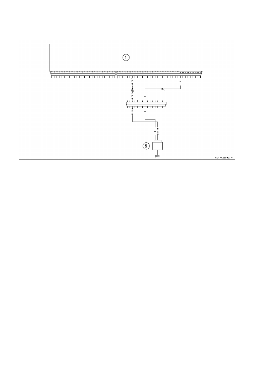
Water Temperature Sensor (Service Code 14)

ZX1200-B3

: Signal

ECU [1]

Water Temperature Sensor [5]

Sensor Resistance Inspection

Remove the water temperature sensor (see this section).

Refer to the Electrical System chapter for water temper-
ature sensor inspection.

FUEL SYSTEM (DFI) 3-87

Atmospheric Pressure Sensor (Service Code 15)

CAUTION

Never drop the sensor, especially on a hard surface.
Such a shock to the sensor can damage it.

Atmospheric Pressure Sensor Removal

Turn the ignition switch off.

Remove:

Seat Cover (see Frame chapter)
Bolts [A]

Remove the atmospheric pressure sensor [B].

Disconnect the sensor connectors [C].

Atmospheric Pressure Sensor Installation

Installation is reverse of removal.

Tighten the sensor bolts.

Torque - Atmospheric Pressure Sensor Bolts: 12 N·m (1.2

kgf·m, 106 in·lb)

NOTE

The atmospheric pressure sensor is the same part as
the inlet air pressure sensor except that the inlet air
pressure sensor has a inlet air pressure hose and dif-
ferent wiring.

Input Voltage Inspection

NOTE

Be sure the battery is fully charged.

The inspection is the same as “Input Voltage Inspection”
of the throttle sensor and the inlet air pressure sensor.

Turn the ignition switch OFF.

Remove the ECU (see this chapter). Do not disconnect
the ECU connectors.

Connect a digital voltmeter [A] to the connector [B], with
the needle adapter set.

Measure the input voltage with the engine stopped, and
with the connectors joined.

Special Tool - Needle Adapter Set: 57001-1457

Turn the ignition switch ON.

Atmospheric Pressure Sensor Input Voltage

Connections to ECU

ZX1200-B1/B2:

Meter (+)

BL/W lead (terminal 41)

Meter (–)

BR/BK lead (terminal 54)

ZX1200-B3

:

Meter (+)

BL/W lead (terminal 10)

Meter (–)

BR/BK lead (terminal 28)

Input Voltage at ECU

Standard:

4.75

5.25 V DC

3-88 FUEL SYSTEM (DFI)

Atmospheric Pressure Sensor (Service Code 15)

If the reading of input voltage is less than the standard
range, check the ECU for its ground, and power supply
(see this chapter). If the ground and power supply are
good, replace the ECU.

If the reading is within the standard range, remove the
seat cover, and check the input voltage again at the sen-
sor connector.

Disconnect the atmospheric pressure sensor connector
and connect the harness adapter between the main har-
ness connector and pressure sensor connector.

Connect a digital meter [A] to the harness adapter leads
[B].

Special Tool - Throttle Sensor Setting Adapter:

57001

-1521

Measure the input voltage with the engine stopped, and
with the connector joined.

Turn the ignition switch ON.

Atmospheric Pressure Sensor Input Voltage

Connections to Sensor

Meter (+)

BL/W lead [C]

Meter (–)

BR/BK lead [D]

Input Voltage at Sensor Connector

Standard:

4.75

5.25 V DC

If the reading is out of the standard range, check the
wiring (see wiring diagram in this section).
If the reading is good, the input voltage is normal. Check
the output voltage.

Turn the ignition switch OFF.

Output Voltage Inspection

Measure the output voltage at the ECU in the same way
as input voltage inspection. Note the following.

Digital Meter [A]
ECU Connector [B]
Needle Adapter Set [C]

FUEL SYSTEM (DFI) 3-89

Atmospheric Pressure Sensor (Service Code 15)

Atmospheric Pressure Sensor Output Voltage

Connections to ECU

ZX1200-B1/B2:

Meter (+)

G/W lead (terminal 45)

Meter (–)

BR/BK lead (terminal 54)

ZX1200-B3

:

Meter (+)

G/W lead (terminal 25)

Meter (–)

BR/BK lead (terminal 28)

Usable Range:

3.46

3.82 V DC at the standard

atmospheric pressure (101.32 kPa,
76 cmHg abs.)

NOTE

The output voltage changes according to the local at-
mospheric pressure.

The atmospheric sensor output voltage is based on
a nearly perfect vacuum in the small chamber of the
sensor. So, the sensor indicates absolute atmospheric
pressure.

If the output voltage is within the usable range, check the
ECU for its ground, and power supply (see this chapter). If
the ground and power supply are good, replace the ECU.

If the output voltage is far out of the usable range, remove
the fuel tank, and check the output voltage at the sensor
connector (when the wiring is open, the output voltage is
about 1.8 V).

Connect a digital meter [A] to the harness adapter leads
[B].

Special Tool - Throttle Sensor Setting Adapter:

57001

-1521

Atmospheric Pressure Sensor Output Voltage

Connections to Sensor

Meter (+)

G/W lead [C]

Meter (–)

BR/BK lead [D]

Output Voltage at Sensor

Usable Range:

3.46

3.82 V DC at the standard

atmospheric pressure (101.32 kPa,
76 cmHg abs)

If the output voltage is normal, check the wiring for conti-
nuity (see next diagram).
If the output voltage is out of the usable range, replace
the sensor.

3-90 FUEL SYSTEM (DFI)

Atmospheric Pressure Sensor (Service Code 15)

ZX1200-B1/B2

: Signal

ECU [1]

Atmospheric Pressure Sensor [38]

ZX1200-B3

: Signal

ECU [1]

Atmospheric Pressure Sensor [14]

If you need to check the atmospheric pressure sensor for
various altitudes other than sea level, check the output
voltage as follows:

Determine the local altitude (elevation).

FUEL SYSTEM (DFI) 3-91

Atmospheric Pressure Sensor (Service Code 15)

If you know the local atmospheric pressure using a
barometer, substitute the atmospheric pressure for throt-
tle vacuum pressure in the inlet air pressure sensor chart
(see Inlet Air Pressure Sensor section in this chapter).
And get the usable range of the atmospheric pressure
sensor output voltage and check if output voltage is
within the standard or not in the same way as Output
Voltage Inspection of the inlet air pressure sensor.

If you know the local altitude, use the following chart.

Atmospheric Pressure/Altitude Relationship

3-92 FUEL SYSTEM (DFI)

Crankshaft Sensor (Service Code 21)

Start the engine and switch the diagnosis mode to Dealer

1 mode to know all the problem that the DFI system has at
the time of self-diagnosis. If the engine cannot be started,
the self-diagnosis system does not detect dynamic condi-
tion of the crankshaft sensor. In this case turn off the igni-
tion switch and turn it on again to enter the Dealer 2 mode.
In this mode the system tells all the troubles which the DFI
system had in both static and dynamic conditions.

Crankshaft Sensor Removal/Installation

See the Ignition System section in the Electrical System
chapter.

Crankshaft Sensor Inspection

The crankshaft have no power source, and when the en-
gine stops, the crankshaft generates no signals.

Crank the engine and measure the peak voltage of the
crankshaft sensor (see Electrical System chapter) in or-
der to check the sensor.

Check the wiring for continuity, using the following dia-
gram.

ZX1200-B1/B2

ECU [1]

Crankshaft Sensor [7]

FUEL SYSTEM (DFI) 3-93

Crankshaft Sensor (Service Code 21)

ZX1200-B3

ECU [1]

Crankshaft Sensor [7]

3-94 FUEL SYSTEM (DFI)

Camshaft Position Sensor (Service Code 23)

Start the engine and switch the diagnosis mode to Dealer

1 mode to know all the problem that the DFI system has at
the time of self-diagnosis. If the engine cannot be started,
the self-diagnosis system does not detect dynamic condi-
tion of the camshaft position sensor. In this case turn off
the ignition switch and turn it on again to enter the Dealer 2
mode. In this mode the system tells all the troubles which
the DFI system had in both static and dynamic conditions.

Camshaft Position Sensor Removal/Installation

The camshaft position sensor detects the position of the

camshaft, and distinguishes the cylinder.

See the Ignition system section in the Electric System
chapter.

Camshaft Position Sensor Inspection

The camshaft position sensor have no power source, and
when the engine stops, the camshaft position sensor gen-
erates no signal.

Crank the engine and measure the peak voltage of the
camshaft position sensor (see Electrical System chapter)
in order to check the sensor.

Check the wiring for continuity, using the following dia-
gram.

ZX1200-B1/B2

ECU [1]

Camshaft Position Sensor [6]

FUEL SYSTEM (DFI) 3-95

Camshaft Position Sensor (Service Code 23)

ZX1200-B3

ECU [1]

Camshaft Position Sensor [6]

3-96 FUEL SYSTEM (DFI)

Speed Sensor (Service Code 24)

Speed Sensor Removal/Installation

See the Electrical System.

Speed Sensor Inspection

See the Electrical System chapter as to the Speed Sen-
sor.

Torque - Speed Sensor Bolt: 10 N·m (1.0 kgf·m, 89 in·lb)

NOTE

Be sure the battery is fully charged.

Turn the ignition switch ON.

Remove the ECU (see this chapter) not to disconnect the
ECU connectors.

Connect a digital voltmeter [A] leads to the connectors [B]
[C] as follows, with the needle adapter set [D], and check
the conductivity between them.

ZX1200-B1/B2:

Meter (+)

Y Lead (terminal 9)

Meter (–)

Y Lead (12P connector)

ZX1200-B3

:

Meter (+)

Y Lead (terminal 11)

Meter (–)

Y Lead (12P connector)

Special Tool - Needle Adapter Set: 57001-1457

If there is not a conductivity between the connector and
the ECU, check the speed sensor and wiring, or replace
the sensor and/or ECU.

FUEL SYSTEM (DFI) 3-97

Speed Sensor (Service Code 24)

ZX1200-B1/B2

ECU [1]

Meter Assembly [39]

Speed Sensor [40]

ZX1200-B3

ECU [1]

Meter Assembly [15]

Speed Sensor [16]

3-98 FUEL SYSTEM (DFI)

Gear Position Switch (Service Code 25)

The gear position switch detects the gear position of the

neutral and running, and sends the signal to the ECU.

The signal is used to determine the basic amount of the

fuel injected.

Gear Position Switch Removal

Remove:

Engine (see Engine Removal/Installation chapter)

Open the clamp [A].

Unscrew the screws [B] and remove the gear position
switch, pin and spring.

Gear Position Switch Installation

Securely place the spring [A] and pin [B] into the hole [C]
of the drum.

Apply grease to the O-ring [D] and install the gear position
switch.

Apply a non-permanent locking agent to the gear position
switch screws and tighten them.

Tighten the lower switch screw [A] with the ground termi-
nal [B].

Torque - Gear Position Switch Screws: 4.0 N·m (0.40 kgf·m,

35 in·lb)

Install the Engine (see Engine Removal/Installation chap-
ter).

FUEL SYSTEM (DFI) 3-99

Gear Position Switch (Service Code 25)

Gear Position Switch Input Voltage Inspection

NOTE

Be sure the battery is fully charged.

Turn the ignition switch OFF.

Remove the ECU (see this chapter). Do not disconnect
the ECU connectors.

Connect a digital voltmeter [A] to the connector [B], with
the needle adapter set [C].

Measure the input voltage with the engine stopped, and
with the connectors joined.

Special Tool - Needle Adapter Set: 57001-1457

Turn the ignition switch ON.

Gear Position Switch Input Voltage Connections to ECU
ZX1200-B1/B2:

Gear Position

Tester (+)

Tester (–)

Neutral

Light Green Lead

20

1st

Green/Red Lead

47

2nd

Green/Blue Lead

53

3rd

Green/Yellow Lead

60

4th

Green Lead

46

5th

Green/White Lead

52

6th

Green/Black Lead

59

Engine

Ground

ZX1200-B3

:

Gear Position

Tester (+)

Tester (–)

Neutral

Light Green Lead

55

1st

Green/Red Lead

37

2nd

Green/Blue Lead

36

3rd

Green/Yellow Lead

35

4th

Green Lead

50

5th

Green/White Lead

49

6th

Yellow/Green Lead

48

Engine

Ground

Input Voltage at ECU (Except gear position)

Standard:

Neutral Battery Voltage (12.5 V or
more) other than Neutral less than 5 V

Input Voltage at ECU (Respective Gear Position)

Standard:

0 V

If the reading of input voltage is out of the standard range,
check the ECU for its ground, and power supply (see this
chapter). If the ground and power supply are good, re-
place the ECU.

3-100 FUEL SYSTEM (DFI)

Gear Position Switch (Service Code 25)

If the reading is within the standard range, set up the fuel
tank, and check the input voltage again at the sensor con-
nector.

Connect a digital voltmeter [H] to the connector [I], with
the needle adapter set.

Measure the input voltage with the engine stopped, and
with the connector joined.

Special Tool - Needle Adapter Set: 57001-1457

Turn the ignition switch ON.

Gear Position Switch Input Voltage Connection to ECU

Gear Position

Tester (+)

Tester (–)

Neutral

Light Green Lead [A]

1st

Blue/Red Lead [B]

2nd

Light Blue Lead [C]

3rd

Red Lead [D]

4th

Blue Lead [E]

5th

Green/Red Lead [F]

6th

Yellow/Green Lead [G]

Engine Ground

For ZX1200-B3 model

; as shown in the figure.

Input Voltage at Gear Position Switch Connector
(Except Gear Position)

Standard:

Neutral Battery Voltage (12.5 V or
more) other than Neutral less than 5 V

Input Voltage at Gear Position Switch Connector
(Respective Gear Position)

Standard:

0 V

If the reading is out of the standard range, check the
wiring (see wiring diagram in this section).
If the reading is good, the input voltage is normal. Check
the gear position switch.

Turn the ignition switch OFF.

Remove the needle adapter set.

Gear Position Switch Inspection

Set up the fuel tank.

Disconnect the gear position switch connector [A].

FUEL SYSTEM (DFI) 3-101

Gear Position Switch (Service Code 25)

Check the switch for continuity at the following gear posi-
tions.

Gear Position

Tester (+)

Tester (–)

Neutral

Light Green Lead [A]

1st

Blue/Red Lead [B]

2nd

Light Blue Lead [C]

3rd

Red Lead [D]

4th

Blue Lead [E]

5th

Green/Red Lead [F]

6th

Yellow/Green Lead [G]

Engine Ground

[H]

For ZX1200-B3 model

; as shown in the figure.

White/Red Lead [I]
Yellow Lead [J]

The switch is normal if there is continuity in the respective
gear positions.
If the switch has an open or short circuit, repair or replace
it.

ZX1200-B1/B2

: Signal

Gear Position Switch [2]

ECU [1]

Junction Box [22]

3-102 FUEL SYSTEM (DFI)

Gear Position Switch (Service Code 25)

ZX1200-B3

: Signal

Gear Position Switch [2]

ECU [1]

FUEL SYSTEM (DFI) 3-103

Vehicle-down Sensor (Service Code 31)

This sensor has a weight [A] with two magnets inside, and

sends a signal to the ECU. But when the motorcycle banks
60

70° or more to either side (in fact falls down), the weight

turns and shuts off the signal. The ECU senses this change,
and stops the fuel pump, the fuel injectors, and the ignition
system.

Hall IC [B]

When the motorcycle is down, the ignition switch is left

ON. If the starter button is pushed, the electric starter turns
but the engine doesn’t start. To start the engine again, raise
the motorcycle, turn the ignition switch OFF, and then ON.
When the ignition switch is turned ON, current flows through
the latch-up circuit and the transistor in the circuit is turned
ON to unlock the latch-up circuit.

Vehicle-down Sensor [A]
Ground Terminal BK/Y [B]
Output Terminal Y/G [C]
Power Source Terminal BR [D]

Vehicle-down Sensor Removal

CAUTION

Never drop the down-sensor, especially on a hard
surface. Such a shock to the sensor can damage it.

Pull the battery tray (see Electrical System chapter).

Remove:

Screw [A]
Cover [B]

Turn Signal Relay [A]
Screws [B]
Vehicle-down Sensor [C]

Push locks on center, and disconnect the connector [D].

3-104 FUEL SYSTEM (DFI)

Vehicle-down Sensor (Service Code 31)

Vehicle-down Sensor Installation

The UP mark [A] of the sensor should face upward.

WARNING

Incorrect installation of the vehicle-down sensor
could cause sudden loss of engine power. The
rider could lose balance during certain riding situ-
ations, like leaning over in a turn, with the potential
for an accident resulting in injury or death. Ensure
that the down sensor is held in place by the sensor
brackets.

Again, make sure the vehicle-down sensor assy is in
place.

Tighten the screws securely [A].

Install battery tray (see Electrical System chapter).

Vehicle-down Sensor Inspection

NOTE

Be sure the battery is fully charged.

Remove:

Battery Tray (see Electrical System chapter)
Cover (see Removal in this section)

Connect:

Battery (–) Terminal [A]
Connectors [B]

CAUTION

Do not short the starter motor cable terminal.

FUEL SYSTEM (DFI) 3-105

Vehicle-down Sensor (Service Code 31)

Connect a digital volt meter [C] to the connector [B] (nat-
ural, 3P) of the vehicle-down sensor [A], with the needle
adapter set [D].

Turn the ignition switch ON, and measure the power
source voltage with the connector joined.

Vehicle-down Sensor Power Source Voltage

Connections to Sensor

Meter (+)

W/Y lead [E]

Meter (–)

BK/Y lead [F]

Power Source Voltage at Sensor

Standard:

Battery Voltage (12.5 V or more)

Turn the ignition switch OFF.
If there is no battery voltage, check the following:

Battery (see Electrical System chapter)
ECU Main Fuse 15 A
Wiring for Vehicle-down Sensor Power Source (see next
diagram)

If the power source is normal, check the output voltage.

Connect a digital volt meter [A] to the connector (natural,
3P), with needle adapter set [B].

Special Tool - Needle Adapter Set: 57001-1457

Turn the ignition switch ON, and measure the output volt-
age with the connector joined.

Remove the sensor.

Tilt the sensor 60

70° or more [C] right or left, then hold

the sensor almost vertical [D] with the arrow mark pointed
up, and measure the output voltage.

Vehicle-down Sensor Output Voltage

Connections to Sensor

Meter (+)

Y/G lead [E]

Meter (–)

BK/Y lead [F]

Output Voltage at Sensor

Standard:

with sensor tilted 60

70° or more

right or left: 3.7

4.4 V with sensor

arrow mark pointed up: 0.4

1.4 V

NOTE

If you need to test again, turn the ignition switch OFF,
and then ON.

3-106 FUEL SYSTEM (DFI)

Vehicle-down Sensor (Service Code 31)

Turn the ignition switch OFF.

Remove the needle adapter set, and apply silicone
sealant to the seals of the connector for waterproofing.

Silicone Sealant (Kawasaki Bond: 56019-120)

- Seals of Vehicle-down Sensor Connector

If the output voltage is normal, the wiring is suspect.
Check the wiring.
If the wiring is good, check the ECU for its ground and
power supply (see this chapter). If the ground and power
supply are good, replace the ECU.
If the output voltage is out of the specified, replace the
vehicle-down sensor.

ZX1200-B1/B2

: Signal

ECU Main Relay [25]

Starter Relay [30]

ECU [1]

ECU Main Fuse 15 A [27]

Main Fuse 30 A [31]

Ignition Switch [17]

Vehicle-down Sensor [28]

Battery [33]

FUEL SYSTEM (DFI) 3-107

Vehicle-down Sensor (Service Code 31)

ZX1200-B3

: Signal

ECU Main Relay [25]

Starter Relay [30]

ECU [1]

ECU Main Fuse 15 A [27]

Main Fuse 30 A [31]

Ignition Switch [17]

Vehicle-down Sensor [28]

Battery [33]

3-108 FUEL SYSTEM (DFI)

Subthrottle Sensor (Service Code 32) (ZX1200-B3

)

Subthrottle Sensor Removal/Adjustment

CAUTION

Do not remove or adjust the subthrottle sensor [A]
since it has been adjusted and set with precision at
the factory.
Never drop the sensor, especially on a hard surface.
Such a shock to the sensor can damage it.

Subthrottle Sensor Connector (black) [B]

Input Voltage Inspection

NOTE

Be sure the battery is fully charged.

Turn the ignition switch OFF.

Disconnect the subthrottle sensor connector (black) [A]
and connect the harness adapter [B] between these con-
nectors.

Connect a digital meter to the harness adapter lead.

Special Tool - Throttle Sensor Harness Adapter: 57001

-1538

Measure the sensor input voltage with the engine stopped
and with the connector joined.

Turn the ignition switch ON.

Subthrottle Sensor Input Voltage

Connections to Adapter

Meter (+)

BK (sensor BL/W) lead

Meter (–)

W (sensor BR/BK) lead

Standard: 4.75

5.25 V DC

Turn the ignition switch OFF.
If the input voltage is normal, check the sensor output
voltage.
If the input voltage is less than the standard, remove the
ECU and check the wiring between these connectors.

Disconnect the ECU and sensor connectors.

Wiring Connection

ECU Connector [A]

←→

Subthrottle Sensor Connector [B]

BL/W lead (ECU terminal 10)
BR/BK lead (ECU terminal 28)

If the wiring is good, check the ECU for its ground and
power supply (see ECU section).

FUEL SYSTEM (DFI) 3-109

Subthrottle Sensor (Service Code 32) (ZX1200-B3

)

Output Voltage Inspection

Measure the output voltage at the subthrottle sensor in
the same way as input voltage inspection. Note the fol-
lowing.

Disconnect the subthrottle sensor connector (black) [A]
and connect the harness adapter [B] between these con-
nectors.

Special Tool - Throttle Sensor Harness Adapter: 57001

-1538

Measure the output voltage of the sensor with the engine
running, and with the connector joined.

Turn the ignition switch ON.

Measure the output voltage when the subthrottle valve is
fully opened or completely closed by hand.

Main Throttle Sensor Output Voltage

Connections to Adapter

Meter (+)

R (sensor BR) lead

Meter (–)

W (sensor BR/BK) lead

Standard:

0.48

0.52 V DC (at idle throttle opening)

3.6

4.0 V DC (at full throttle opening)

If the output voltage is out of the standard, inspect the
subthrottle sensor resistance.
If the output voltage is normal, check the wiring for conti-
nuity.

Wiring Connection

ECU Connector [A]

←→

Subthrottle Sensor Connector [B]

BR lead (ECU terminal 24)
BR/BK lead (ECU terminal 28)

If the wiring is good, check the ECU for its ground and
power supply (see ECU section).

3-110 FUEL SYSTEM (DFI)

Subthrottle Sensor (Service Code 32) (ZX1200-B3

)

Resistance Inspection

Turn the ignition switch OFF.

Disconnect the subthrottle sensor connector.

Connect a digital meter [A] to the subthrottle sensor con-
nector [B].

Measure the subthrottle sensor resistance.

Throttle Sensor Resistance

Connections:

BL/W lead [C]

←→

BR/BK lead [D]

Standard:

4

6 k

If the reading is out of the range, replace the throttle body
assy.
If the reading is within the range, but the problem still
exists, replace the ECU (see this chapter).

1. ECU

10. Subthrottle Valve Actuator

11. Subthrottle Sensor

A. Throttle Body Assy Connector

FUEL SYSTEM (DFI) 3-111

Immobilizer Amplifier (Service Code 35) (ZX1200-B3

)

Antenna Resistance Inspection

Remove:

Left Lower Inner Cover (see Frame chapter)

Disconnect:

Antenna Lead Connector [A]

Measure the resistance of the antenna coil in the ignition
switch as follows.

Antenna Resistance

Connections to Antenna

Meter

Red Lead

Meter

Red Lead

Standard:

About 0.6

0.9

If the resistance is out of the standard range, replace the
ignition switch.

Amplifier Input Voltage Inspection

NOTE

Be sure the battery is fully charged.

Turn the ignition switch OFF.

Remove:

Upper Fairing (see Frame chapter)

Connect a digital voltmeter to the connectors, using the
needle adapter set.

Special Tool - Needle Adapter Set: 57001-1457

Amplifier Input Voltage

Connections to Connectors

Meter (+)

BR/W Lead in Meter Lead Connector [A]

Meter (–)

BK/Y Lead in Amplifier Lead Connector [B]

Measure the input voltage DC with the connectors joined.

Turn the ignition switch ON.

Input Voltage

Standard:

Battery Voltage

Turn the ignition switch OFF.
If the reading is out of the range, check the wiring (see
wiring diagram in next section).
If the reading and antenna resistance are good, replace
the amplifier.

3-112 FUEL SYSTEM (DFI)

Blank Key Detection (Service Code 36) (ZX1200-B3

)

This code appears in the following conditions.

The transponder [A] in the master and/or user key is mal-
function.

When the spare key of unregistration is used.

When the master key is registered in the registered ECU.

Therefore, the service code 36 will disappear when the
above issue is solved.

User Key Inspection

Register the user key correctly (see Electrical System
chapter).
If the service code 36 appears again, the transponder in
the key is malfunction, replace it.

1. Immobilizer Amplifier
2. Immobilizer Antenna
3. Ignition Switch
4. Meter Unit
5. FI Indicator Light (LED)
6. Ignition Fuse 10 A
7. ECU Fuse 15 A
8. Junction Box

9. ECU Main Relay

10. Starter Relay

11. Main Fuse 30 A

12. Battery
13. Immobilizer/Kawasaki Diagnostic

System Connector

14. ECU

FUEL SYSTEM (DFI) 3-113

Fuel Injectors (#1, #2, #3, #4: Service Code 41, 42, 43, 44)

Fuel Injector #1: (Service Code 41)
Fuel Injector #2: (Service Code 42)
Fuel Injector #3: (Service Code 43)
Fuel Injector #4: (Service Code 44)

CAUTION

Never drop the injector, especially on a hard sur-
face. Such a shock to the injector can damage it.

NOTE

Do not remove the injectors from the throttle body.

Power Source Voltage Inspection

NOTE

Be sure the battery is fully charged.

Turn the ignition switch OFF.

Remove the ECU (see this chapter). Do not disconnect
the ECU connectors.

Connect a digital voltmeter [A] to the connector [B], with
the needle adapter set [C].

Measure the power source voltage with the engine
stopped, and with the connectors joined.

Special Tool - Needle Adapter Set: 57001-1457

Turn the ignition switch ON.

Injector Power Source Voltage at ECU

Connections to ECU
ZX1200-B1/B2:

Meter (+)

W/R lead (terminal 42)

ZX1200-B3

:

Meter (+)

W/R lead (terminal 33)

Meter (–)

Battery (–) Terminal

Power Source Voltage at ECU

Standard:

Battery Voltage (12.5 V or more)

Meter (–)

Battery (–) Terminal

If the power source voltage is less than the standard,
check the ECU for its ground, and power supply (see this
chapter). If the ground and power supply are good, re-
place the ECU.

3-114 FUEL SYSTEM (DFI)

Fuel Injectors (#1, #2, #3, #4: Service Code 41, 42, 43, 44)

If the reading is normal, check the power source voltage
at the injector connector [B], with a digital volt meter [A].

Measure the power source voltage with the engine
stopped, and the connector joined, with a digital meter
and needle adapter set [C].

Turn the ignition switch ON.

Injector #1 BL/R Lead [E]
Injector #2 BL/G Lead [F]
Injector #3 BL/BK Lead [G]
Injector #4 BL/Y Lead [H]
Injector Power Supply W/R Lead [I]

Injector Power Source Voltage at Injector

Connections to Injector #1, #2, #3, #4

Meter (+)

W/R lead [I]

Meter (–)

Battery (–) Terminal [D]

Power Source Voltage at Injector Connector

Standard:

Battery Voltage (12.5 V or more)

Turn the ignition switch OFF.
If the reading is out of the standard, check the wiring (see
wiring diagram in this section).
If the reading is good, and the power source voltage is
normal, check the output voltage.

FUEL SYSTEM (DFI) 3-115

Fuel Injectors (#1, #2, #3, #4: Service Code 41, 42, 43, 44)

Output Voltage Inspection

Measure the output voltage at the ECU connector in the
same way as power source voltage inspection. Note the
following.

Injector Output Voltage at ECU

ZX1200-B1/B2:

Connections for Injector #1

Meter (+)

BL/R lead (terminal 4)

Meter (–)

Battery (–) Terminal

Connections for Injector #2

Meter (+)

BL/G lead (terminal 5)

Meter (–)

Battery (–) Terminal

Connections for Injector #3

Meter (+)

BL/BK lead (terminal 6)

Meter (–)

Battery (–) Terminal

Connections for Injector #4

Meter (+)

BL/Y lead (terminal 7)

Meter (–)

Battery (–) Terminal

ZX1200-B3

:

Connections for Injector #1

Meter (+)

BL/R lead (terminal 44)

Meter (–)

Battery (–) Terminal

Connections for Injector #2

Meter (+)

BL/G lead (terminal 43)

Meter (–)

Battery (–) Terminal

Connections for Injector #3

Meter (+)

BL/BK lead (terminal 42)

Meter (–)

Battery (–) Terminal

Connections for Injector #4

Meter (+)

BL/Y lead (terminal 41)

Meter (–)

Battery (–) Terminal

Output Voltage at ECU

Standard:

Battery Voltage (12.5 V or more)

If the output voltage is normal, check the ECU for its
ground, and power supply (see this chapter).

If the

ground and power supply are good, replace the ECU.

3-116 FUEL SYSTEM (DFI)

Fuel Injectors (#1, #2, #3, #4: Service Code 41, 42, 43, 44)

If the output voltage is out of the standard, remove the
left lower inner cover, and check the output voltage at the
injector connector [B] using a digital meter [A] and needle
adapter set [C] (when the lead is open, the output voltage
is 0 V).

Injector Output Voltage at Injector

Connections to Injector #1

Meter (+)

BL/R lead [E]

Meter (–)

Battery (–) Terminal [D]

Connections to Injector #2

Meter (+)

BL/G lead [F]

Meter (–)

Battery (–) Terminal [D]

Connections to Injector #3

Meter (+)

BL/BK lead [G]

Meter (–)

Battery (–) Terminal [D]

Connections to Injector #4

Meter (+)

BL/Y lead [H]

Meter (–)

Battery (–) Terminal [D]

Output Voltage at Injector Connector

Standard:

Battery Voltage (12.5 V or more)

If the output voltage is normal, check the wiring for con-
tinuity (see next diagram). If the wiring is good, perform
“Audible Inspection” for confirmation.
If the output voltage is out of the standard, perform “Au-
dible Inspection” for confirmation.

Audible Inspection

Start the engine.

Apply the tip of a screwdriver [A] to the injector [C]. Put
the grip end onto your ear, and listen whether the injector
is clicking or not.

A sound scope [B] can also be used.

Do the same for the other injector.
If all the injectors click at a regular intervals, the injectors
are good.

The click interval becomes shorter as the engine speed
rises.
If either injector doesn’t click, perform the “Injector Signal
Test” for injector operation.

FUEL SYSTEM (DFI) 3-117

Fuel Injectors (#1, #2, #3, #4: Service Code 41, 42, 43, 44)

Injector Signal Test

Prepare two test light sets with male terminals as shown.

Rating of Bulb [A]: 12 V × 3

3.4 W

Terminal Width [B]: 1.8 mm (0.07 in.)
Terminal Thickness [C]: 0.8 mm (0.03 in.)

CAUTION

Do not use larger terminals than specified above. A
larger terminal could damage the injector main har-
ness connector (female), leading to harness repair
or replacement.
Be sure to connect bulbs in series. The bulb works
as a current limiter to protect the solenoid in the
injector from excessive current.

Remove connectors for injector [A].

Connect each test light set [B] to the injector sub harness
connector [C].

Turn the ignition switch ON.

While cranking the engine with the starter motor, watch
the test lights.
If the test lights flicker at regular intervals, the injector
circuit in the ECU, and the wiring are good. Perform the
“Injector Resistance Inspection”.

Injector signals can be also confirmed by connecting the
hand tester (× 10 V AC) instead of the test light set to
the injector main harness (female) connector. Crank the
engine with the starter motor, and check to see if the hand
oscillates at regular intervals.

Special Tool - Hand Tester: 57001-1394

If the test light doesn’t flicker (or the test hand doesn’t
oscillates), check the wiring and connectors again If the
wiring is good, replace the ECU.

Injector Resistance Inspection

Remove the throttle body assy (see Throttle Body Assy
Removal).

Disconnect the connector [B] from the injector (see Throt-
tle Body Disassembly/Assembly).

Measure the injector resistance with the hand tester [A].

Special Tool - Hand Tester: 57001-1394

Injector Resistance

Connections to Injector

Meter (+)

Meter (–)

#1: W/R

←→

BL/R Terminal

#2: W/R

←→

BL/G Terminal

#3: W/R

←→

BL/BK Terminal

#4: W/R

←→

BL/Y Terminal

Standard:

ZX1200-B1/B2 about 12.5

@20°C

(68°F)
ZX1200-B3

about 12.0

@20°C

(68°F)


Content      ..     5      6      7      8     ..