Kawasaki Ninja 300 / Ninja 300 ABS Motorcycle. Service Manual (2013) - page 17
 

  Index      Manuals     Kawasaki Ninja 300 / Ninja 300 ABS Motorcycle. Service Manual (2013)


Search            copyright infringement  


Content      ..     15      16      17      18     ..


Kawasaki Ninja 300 / Ninja 300 ABS Motorcycle. Service Manual (2013) - page 17


16-46 ELECTRICAL SYSTEM

Electric Starter System

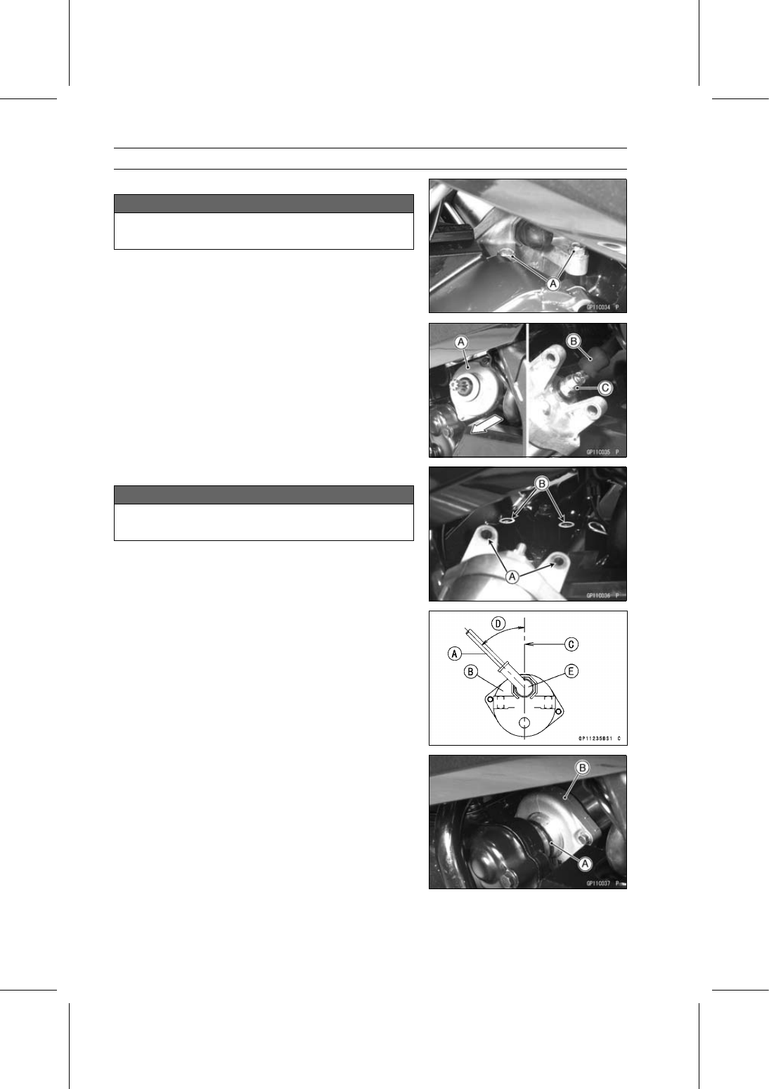
Starter Motor Removal

NOTICE

Do not tap the starter motor shaft or body. Tapping
the shaft or body could damage the motor.

Remove the clutch cable and clutch cable bracket.

Remove the starter motor mounting bolts [A].

Pull the starter motor [A] to the right side then pull out it
toward the left side.

Slide back the rubber cap [B] and remove the starter mo-
tor cable terminal nut [C].

Remove the starter motor.

Starter Motor Installation

NOTICE

Do not tap the starter motor shaft or body. Tapping
the shaft or body could damage the motor.

When installing the starter motor, clean the starter mo-
tor legs [A] and crankcase [B] where the starter motor is
grounded.

Connect the starter motor cable [A] to the starter motor
[B].

Position the starter motor cable as shown.

[C] Vertical Line
[D] Approx. 45°

Torque - Starter Motor Cable Terminal Nut: 9.8 N·m (1.0

kgf·m, 87 in·lb)

Slide the rubber cap [E] to the original position.

Replace the O-ring [A] with a new one and apply grease
to the O-ring.

Position the starter motor [B] on the crankcase and tighten
the starter motor mounting bolts.

Torque - Starter Motor Mounting Bolts: 9.8 N·m (1.0 kgf·m,

87 in·lb)

ELECTRICAL SYSTEM 16-47

Electric Starter System

Starter Motor Disassembly

Remove the starter motor (see Starter Motor Removal).

Remove the starter motor through bolts [A].

Remove the both end covers [A].

Remove the armature [B] from the yoke [C].

Remove:

Starter Motor Terminal Locknut [A]
Washer [B]
Insulator [C]
O-ring [D]

Remove:

Terminal [A]
Brush Holder Screw [B]
Brushes [C]
Brush Springs
Brush Holder [D]

16-48 ELECTRICAL SYSTEM

Electric Starter System

Starter Motor Assembly

Install:

Brush Holder [A]
Negative Brush [B]
Brush Holder Screw [C]
Positive brush [D]
Terminal [E]
Brush Springs [F]

NOTE

Make sure the brush base plates are properly fitted into
the grooves on the brush holder.

Tighten:

Torque - Starter Motor Brush Holder Screw: 3.8 N·m (0.39

kgf·m, 34 in·lb)

Install the brushes on the brush springs.

Replace the O-ring [A] with a new one.

Install the following parts to the starter motor terminal [B].

O-ring
Insulator [C]
Washer [D]
Starter Motor Terminal Locknut [E]

Install the insulator so that stepped side faces outward.

Tighten:

Torque - Starter Motor Terminal Locknut:

11 N·m (1.1

kgf·m, 97 in·lb)

Apply thin coat of grease to the oil seal [A].

Replace the O-ring [B] with a new one.

Replace the seal rings [A] with new ones.

Wrap the pinion gear portion with the vinyl tape to prevent
the oil seal from damaging during installation.

Insert the armature [B] into the left end cover [C].

ELECTRICAL SYSTEM 16-49

Electric Starter System

Install the yoke [A] over the armature so that the cut-out
[B] on the yoke faces commutator side [C].

Make sure the brush springs and brushes [D] are installed
in place.

Align the tab [E] with the cut-out on the yoke to install the
right end cover to the yoke.

Make sure the stamped mark [A] and terminal [B] are
properly positioned as shown.

Turn the left end cover [C] if necessary.

Tighten:

Torque - Starter Motor Through Bolts [A]: 5.0 N·m (0.51

kgf·m, 44 in·lb)

Brush Inspection

Measure the length of each brush [A].
If any is worn down to the service limit, replace the brush
assy.

Starter Motor Brush Length

Standard:

12 mm (0.47 in.)

Service Limit: 6.5 mm (0.26 in.)

Commutator Cleaning and Inspection

Clean the metallic debris off the between commutator
segments [A].

NOTE

Do not use emery or sand paper on the commutator.

Check the commutator for damage or abnormal wear.
Replace the starter motor with a new one if there is any
damage or wear.

Visually inspect the commutator segments for discol-
oration.
Replace the starter motor with a new one if discoloration
is noticed.

16-50 ELECTRICAL SYSTEM

Electric Starter System

Armature Inspection

Using the × 1

hand tester range, measure the resis-

tance between any two commutator segments [A].

Special Tool - Hand Tester: 57001-1394

If there is a high resistance or no reading (

) between any

two segments, a winding is open and the starter motor
must be replaced.

Using the highest hand tester range, measure the resis-
tance between the segments and the shaft [B].
If there is any reading at all, the armature has a short and
the starter motor must be replaced.

NOTE

Even if the foregoing checks show the armature to be
good, it may be defective in some manner not readily
detectable with the hand tester. If all other starter motor
and starter motor circuit components check good, but
the starter motor still does not turn over or only turns
over weakly, replace the starter motor with a new one.

Brush Lead Inspection

Using the × 1

hand tester range, measure the resis-

tance as shown.

Terminal Bolt and Positive Brushes [A]
End Cover and Negative Brushes [B]

Special Tool - Hand Tester: 57001-1394

If there is not close to zero ohms, the brush lead has an
open. Replace the brush plate assy.

End Cover Inspection

Using the highest hand tester range, measure the resis-
tance as shown.

Terminal Bolt and End Cover [A]
Terminal Bolt and Negative Brushes [B]

Special Tool - Hand Tester: 57001-1394

If there is any reading, the brush assy and/or terminal bolt
assy have a short. Replace the starter motor.

Starter Relay Inspection

Remove:

Battery [A] (see Battery Removal)

Pull the starter relay rearward to remove it from the
bracket.

Disconnect the connector [B] from the starter relay [C].

ELECTRICAL SYSTEM 16-51

Electric Starter System

Remove:

Cable Terminal Bolts [A]
Starter Relay [B]

Connect the hand tester [A] and 12 V battery [B] to the
starter relay [C] as shown.

Special Tool - Hand Tester: 57001-1394

If the relay does not work as specified, the relay is defec-
tive. Replace the relay.

Testing Relay

Tester Range:

× 1

range

Criteria:

When battery is connected

0

When battery is disconnected

→ ∞ Ω

16-52 ELECTRICAL SYSTEM

Electric Starter System

Electric Starter Circuit

1. Ignition Switch
2. Engine Stop Switch
3. Starter Button
4. Neutral Switch
5. Water-proof Joint 5
6. Water-proof Joint 7
7. Water-proof Joint 1
8. Frame Ground
9. Sidestand Switch

10. Engine Ground

11. Battery 12 V 8 Ah

12. Starter Relay
13. Main Fuse 30 A
14. Starter Motor
15. Relay Box
16. Starter Circuit Relay
17. Fuse Box 1
18. Ignition Fuse 10 A
19. Starter Lockout Switch

ELECTRICAL SYSTEM 16-53

Lighting System

This motorcycle adopt the daylight system and have a

headlight relay in the relay box. The headlight does not
go on when the ignition switch and the engine stop switch
are first turned on. The headlight comes on after the starter
button is released and stays on until the ignition switch is
turned off. The headlight will go out momentarily whenever
the starter button is pressed and come back on when the
button is released.

Headlight Beam Horizontal Adjustment

Refer to the Headlight Aiming Inspection in the Periodic
Maintenance chapter.

Headlight Beam Vertical Adjustment

Refer to the Headlight Aiming Inspection in the Periodic
Maintenance chapter.

Headlight Bulb Replacement

Remove:

Middle Fairing (see Middle Fairing Removal in the Frame
chapter)
Headlight Bulb Dust Cover [A]

Remove:

Hook [A]
Headlight Bulb [B]

NOTICE

When handling the quartz-halogen bulb, never
touch the glass portion with bare hands. Always
use a clean cloth. Oil contamination from hands or
dirty rags can reduce bulb life or cause the bulb to
explode.

NOTE

Clean off any contamination that inadvertently gets on
the bulb with alcohol or soap and water solution.

Replace the headlight bulb.

Fit the projection [A] on the bulb in the cutout [B] on the
headlight.

16-54 ELECTRICAL SYSTEM

Lighting System

Install the hook [A] and connect the connector [B] to the
headlight bulb.

Fit the dust cover [A] onto the headlight housing with its
lead toward downward.

After installation, adjust the headlight aim (see Headlight
Aiming Inspection in the Periodic Maintenance chapter).

Headlight Removal/Installation

Remove:

Upper Fairing (see Upper Fairing Removal in the Frame
chapter)
Bolts [A]
Headlight [B]

Installation is the reverse of removal.

City Light Bulb Replacement

Remove the middle fairing (see Middle Fairing Removal
in the Frame chapter).

Pull out the socket [A] from the headlight housing.

Pull out the bulb [A] straight from the socket.

NOTICE

Do not turn the bulb. Pull the bulb out to prevent
damage to the bulb. Do not use bulb rated for
greater wattage then the specified value.

Replace the bulb with a new one.

ELECTRICAL SYSTEM 16-55

Lighting System

Tail/Brake Light Bulb Replacement

Remove the rear seat (see Rear Seat Removal in the
Frame chapter).

Turn the socket [A] counterclockwise to remove it.

Push the bulb [A] in the socket, turn it counterclockwise
and pull it out.

Insert the new bulb by aligning its pins [B] with the grooves
[C] in the socket, and turn the bulb clockwise.

Turn the bulb about 15°.

Fit the projection [A] of the socket into the groove [B] of
the tail/brake light.

Turn the socket clockwise.

Tail/Brake Light Removal

Remove:

Seat Covers (see Seat Cover Removal in the Frame
chapter)
Flap Assembly (see Flap and Rear Fender Removal in
the Frame chapter)
Tail/Brake Light Socket (see Tail/Brake Light Bulb Re-
placement)

Push the tab [A] to unhook the rear fender from the frame.

Remove the tail/brake light mounting screws [B] while
pulling down the rear of the fender.

Remove the tail/brake light [C].

Tail/Brake Light Installation

Installation is the reverse of removal.

Run the lead correctly (see Cable, Wire, and Hose Rout-
ing section in the Appendix chapter).

16-56 ELECTRICAL SYSTEM

Lighting System

License Plate Light Bulb Replacement

Remove:

Screws [A]
License Plate Light Cover [B]

Pull the bulb [A] out of the socket [B].

NOTICE

Do not turn the bulb. Pull the bulb out to prevent
damage to the bulb. Do not use bulb rated for
greater wattage then the specified valve.

Replace the bulb with a new one.

Insert the bulb into the socket.

Install the license plate light cover.

ELECTRICAL SYSTEM 16-57

Lighting System

Headlight/Tail Light Circuit

1. Ignition Switch
2. Alternator
3. License Plate Light 12

V 5 W

4. Tail/Brake Light 12 V

21/5 W

5. Frame Ground
6. Engine Ground
7. Battery 12 V 8 Ah

8. Starter Relay
9. Main Fuse 30 A

10. Fuse Box 1

11. Headlight Fuse 15 A

12. Fuse Box 2
13. Turn Signal Relay Fuse 10 A
14. Relay Box
15. Headlight Circuit Relay
16. Passing Button

17. Dimmer Switch
18. Left City Light 12 V 5 W
19. Headlight (High Beam) 12 V

55 W

20. Headlight (Low Beam) 12 V

55 W

21. Right City Light 12 V 5 W
22. Water-proof Joint 8
23. Meter Unit

Turn Signal Light Bulb Replacement

Remove the screw [A] and lens [B].

16-58 ELECTRICAL SYSTEM

Lighting System

Push and turn the bulb [A] counterclockwise and remove
it.

Insert the new bulb [A] by aligning its pins [B] with the
grooves [C] in the socket, and turn the bulb clockwise.

Turn the bulb about 15°.

Fit the projection [A] on the lens to the groove [B] on the
socket.

Tighten the screw.

Turn Signal Relay Inspection

Remove:

Left Seat Cover (see Seat Cover Removal in the Frame
chapter)
Turn Signal Relay [A]

Disconnect:

Connector [B]

ELECTRICAL SYSTEM 16-59

Lighting System

Connect one 12 V battery and turn signal lights as indi-
cated in the figure, and count how may times the lights
flash for one minute.

Turn Signal Relay [A]
Turn Signal Lights [B]
12 V Battery [C]

If the lights do not flash as specified, replace the turn sig-
nal relay.

Testing Turn Signal Relay

Load

The Number of Turn

Signal Lights

Wattage (W)

Flashing Times

(c/m*)

1**

10

Lights stays on

2

20

75

95

(*): Cycle(s) per minute

(**): Corrected to "one light burned out".

16-60 ELECTRICAL SYSTEM

Lighting System

Turn Signal Light Circuit

1. Ignition Switch
2. Water-proof Joint 1
3. Rear Right Turn Signal Light 12 V 10 W
4. Rear Left Turn Signal Light 12 V 10 W
5. Frame Ground
6. Engine Ground
7. Battery 12 V 8 Ah
8. Starter Relay
9. Main Fuse 30 A

10. Fuse Box 2

11. Turn Signal Relay Fuse 10 A

12. Turn Signal Relay
13. Turn Signal Switch
14. Front Left Turn Signal Light 12 V 10 W
15. Front Right Turn Signal Light 12 V 10 W
16. Meter Unit

ELECTRICAL SYSTEM 16-61

Air Switching Valve

Air Switching Valve Operation Test

Refer to the Air Suction System Damage Inspection in the
Periodic Maintenance chapter.

Air Switching Valve Unit Test

Remove the air switching valve (see Air Switching Valve
Removal in the Engine Top End chapter).

Set the hand tester [A] to the × 1

range and connect it

to the air switching valve terminals as shown in the figure.

Special Tool - Hand Tester: 57001-1394

Air Switching Valve Resistance

Standard:

20

24

at 20°C (68°F)

If the tester does not read as specified value, replace it
with a new one.

Connect the 12 V battery [A] to the air switching valve
terminals as shown in the figure.

Blow the air to the intake air duct [A], and make sure does
not flow the blown air from the outlet air duct [B].

Disconnect the 12 V battery.

Blow the air to the intake air duct [A] again, and make sure
flow the blown air from the outlet air duct [B].
If the air switching valve does not operate as described,
replace it with a new one.

NOTE

To check air flow through the air switching valve, just
blow through the air switching valve hose (intake side).

16-62 ELECTRICAL SYSTEM

Air Switching Valve

Air Switching Valve Circuit

1. ECU
2. Water-proof Joint 1
3. Water-proof Joint 2
4. Frame Ground
5. Engine Ground
6. Battery 12 V 8 Ah
7. Main Fuse 30 A
8. Starter Relay
9. Fuse Box 1

10. FI Fuse 15 A

11. Ignition Fuse 10 A

12. Relay Box
13. ECU Main Relay
14. Water-proof Joint 8
15. Ignition Switch
16. Air Switching Valve

ELECTRICAL SYSTEM 16-63

Radiator Fan System

Fan Motor Inspection

Remove the fuel tank (see Fuel Tank Removal in the Fuel
System (DFI) chapter).

Disconnect the connector [A].

Using an auxiliary leads, supply battery power to the fan
motor.
If the fan does not rotate, the fan motor is defective and
must be replaced.

16-64 ELECTRICAL SYSTEM

Radiator Fan System

Radiator Fan Circuit

1. ECU
2. Joint Connector 2
3. Frame Ground
4. Engine Ground
5. Battery 12 V 8 Ah
6. Main Fuse 30 A
7. Starter Relay
8. Fuse Box 1
9. Fan Fuse 10 A

10. Ignition Fuse 10 A

11. Relay Box

12. Fan Relay
13. Water-proof Joint 7
14. Ignition Switch
15. Fan Motor
16. Water-proof Joint 3
17. Water Temperature Sensor

ELECTRICAL SYSTEM 16-65

Meter, Gauge, Indicator Unit

Meter Unit Removal/Installation

Remove:

Instrument Cover (see Instrument Cover Removal in the
Frame chapter)
Screws [A]
Clamps [B]

NOTICE

Place the meter unit so that the face is up. If a meter
unit is left upside down or sideways for any length
of time, it will malfunction.

Do not try to disassemble the meter unit.

Installation is the reverse of removal.

Run the leads and cable correctly (see Cable, Wire, and
Hose Routing section in the Appendix chapter).

Install the removed parts (see appropriate chapters).

Meter Unit Inspection

Remove the meter unit (see Meter Unit Removal).

[1] Green Left Turn Signal Indicator Light (LED)
[2] Green Right Turn Signal Indicator Light (LED)
[3] Green Neutral Indicator Light (LED) (–)
[4] Blue High Beam Indicator Light (LED) (+)
[5] Red Oil Pressure Warning Indicator Light (LED)
[6] Battery (+)
[7] Unused
[8] Fuel Level Gauge
[9] Yellow ABS Indicator Light (LED) (ABS Equipped

Model only)

[10] Yellow Engine Warning Indicator Light (LED)

[11] Unused

[12] Tachometer Signal
[13] Unused
[14] Speed Sensor Signal
[15] Ground (–)
[16] Ignition (+)

NOTICE

Do not drop the meter unit. Place the meter unit so
that it faces upward. If the meter unit is left upside
down or sideways for a long time or dropped, it will
malfunction. Do not short each terminals.

16-66 ELECTRICAL SYSTEM

Meter, Gauge, Indicator Unit

Liquid Crystal Display (LCD) Segment Check

Using the auxiliary leads, connect the 12 V battery to the
meter unit connector as follows.

Battery Positive (+) Terminal to Terminal [6] and [16]
Battery Negative (–) Terminal to Terminal [15]

Then the tachometer needle [A] sweeps to the maximum
reading, then sweeps back to the minimum reading.

The following should appear.

Yellow ABS Indicator Light (LED) [B] (ABS Equipped
Model only)
LCD Segments [C]
LED Illumination Light [D]

The following should appear for 2 seconds.

Red Oil Pressure Warning Indicator Light (LED) [E]
Yellow Engine Warning Indicator Light (LED) [F]
Red Battery Voltage Warning Indicator Light (LED) [G]
Red Water Temperature Warning Indicator Light (LED)
[H]
Blue High Beam Indicator Light (LED) [I]
Green Turn Signal Indicator Lights (LED) [J]

The all segments of the fuel gauge in the display will blink.
(This function is Fuel Level Sensor Line Self-Diagnosis
Mode. Refer to Fuel Level Sensor Line Self-Diagnosis
Mode Inspection.)
If the multifunction meter does not work as above, replace
the meter assembly.

Disconnect the terminal [16].

The LED illumination light, LCD segments and all the
warning indicator lights should disappear.
If the multifunction meter does not work as above, replace
the meter assembly.

ELECTRICAL SYSTEM 16-67

Meter, Gauge, Indicator Unit

Left and Right Button Operation Check

Connect the 12 V battery and terminals in the same man-
ner as specified in the “Liquid Crystal Display (LCD) Seg-
ments Check”.

Check that the multifunction meter displays shift as shown
when the left button [A] is pressed.
If the multifunction meter display function does not work,
replace the meter assembly.

Display the odometer.

Check that when the right button [A] is pressed for more
than 2 seconds in ODO mode, the multifunction meter
display turns to the clock set mode.

Both the hour and minute display start blinking.

In the HOUR/MINUTE setting mode, press the right but-
ton again to effect the HOUR setting mode.

The hour display blinks on the display.

Press the left button to set the hour.

In the HOUR setting mode, press the right button to effect
the MINUTE setting mode.

The minute display blinks on the display.

Press the left button to set the minute.

16-68 ELECTRICAL SYSTEM

Meter, Gauge, Indicator Unit

In the MINUTE setting mode, press the right button to
return the HOUR/MINUTE setting mode.

Press the left button to complete the clock setting process.

The clock starts counting the seconds as soon as the left
button is pressed.

Display the odometer.

Check that the multifunction meter displays shift as shown
by pressing the right button while the left button pressed
in.

NOTE

Km/h, mph display can alternate between English and
metric modes (mile and km) [A] in the digital meter.
Make sure that km/h or mph according to local regu-
lations is correctly displayed before riding.

If the multifunction meter display function does not work,
replace the meter assembly.

Speedometer Check

Connect the 12 V battery and terminals in the same man-
ner as specified in the “Liquid Crystal Display (LCD) Seg-
ments Check”.

The speed equivalent to the input frequency is indicated in
the oscillator [A], if the square wave (illustrated as shown)
would be input into the terminal [14].

Indicates approximately 60 mph in case the input fre-
quency would be approximately 166.9 Hz.

Indicates approximately 60 km/h in case the input fre-
quency would be approximately 104.3 Hz.
If the oscillator is not available, the speedometer can be
checked as follows.

Install the meter unit (see Meter Unit Installation).

Raise the rear wheel off the ground using the stand (see
Rear Wheel Removal in the Wheels/Tires chapter).

Turn the ignition switch on.

Rotate the rear wheel by hand.

Check that the speedometer shows the speed.
If the speedometer does not work, replace the meter as-
sembly.

NOTE

The input frequency of the oscillator adds the integrated
value of the odometer.

The integrated value of the odometer cannot be reset.

ELECTRICAL SYSTEM 16-69

Meter, Gauge, Indicator Unit

Odometer Check

Check the odometer with the speedometer in the same
way.
If the value indicated in the odometer is not added, re-
place the meter assembly.

NOTE

The integrated value of the odometer cannot be reset.

When the figures come to 999999, they are stopped and
locked.

Trip Meter A/B Check

Check the trip meter A/B with the speedometer in the
same way.
If the value indicated in the trip meter A/B is not added,
replace the meter assembly.

Check that the figure display turns to 0.0 when the right
button is pressed for more than 2 seconds.
If the figure displayed in the trip meter A/B does not indi-
cate 0.0, replace the meter assembly.

NOTE

The integrated value of the odometer cannot be reset.

Tachometer Check

Connect the 12 V battery and terminals in the same man-
ner as specified in the “Liquid Crystal Display (LCD) Seg-
ments Check”.

The revolutions per minute (rpm) equivalent to the input
frequency is indicated in the oscillator [A] if the square
wave (illustrated as shown) would be input into the termi-
nal [12].

Indicates approximately 4 000 rpm in case the input fre-
quency would be approximately 133.3 Hz.

If the oscillator is not available, the tachometer can be
checked as follows.

Connect the 12 V battery and terminals in the same man-
ner as specified in the “Liquid Crystal Display (LCD) Seg-
ments Check”.

Then the tachometer needle [A] sweeps to the maximum
reading [B], then sweeps back to the minimum reading
[C].
If the tachometer needle does not sweep, replace the me-
ter assembly.

Using the insulated auxiliary lead, quickly open and con-
nect the terminal [16] to the terminal [12] repeatedly.

Then the tachometer needle should flick.
If the tachometer needle does not flick, replace the meter
assembly.

16-70 ELECTRICAL SYSTEM

Meter, Gauge, Indicator Unit

Fuel Level Sensor Line Self-Diagnosis Mode Inspection

NOTE

Usually when the open or short of the fuel level sensor
circuit is detected, it becomes the Fuel Level Sensor
Line Self-Diagnosis Mode.

The all segments of the fuel gauge [A] and fuel warning
symbol [B] in the display will blink. (This function is Fuel
Level Sensor Line Self-Diagnosis Mode.)
If the meter enters the self-diagnostic mode when the me-
ter is installed in the motorcycle, check the fuel level sen-
sor (see Fuel Level Sensor Inspection).
If the fuel level sensor and wiring are good, replace the
meter unit.

Fuel Level Gauge Check

Connect the 12 V battery and terminals in the same man-
ner as specified in the “Liquid Crystal Display (LCD) Seg-
ments Check”.

Connect the variable rheostat [A] between the terminal [8]
and ground.

Check that the number of segments [A] matches the re-
sistance value of the variable rheostat.

Variable Rheostat

Resistance (

)

Display Segments

9.5

15.4

6

61.9

97.8

4

178.7

197.4

1

If the multifunction meter display function does not work,
replace the meter assembly.

Fuel Level Warning Check

Connect the 12 V battery and terminals in the same man-
ner as specified in the “Liquid Crystal Display (LCD) Seg-
ments Check”.

Connect the variable rheostat [A] between the terminal [8]
and ground.

Adjust the resistance value to the approximately 216

.

ELECTRICAL SYSTEM 16-71

Meter, Gauge, Indicator Unit

Check that one segment [A] in the fuel gauge starts blink-
ing.

Check that the fuel warning symbol [B] blinks.
If the multifunction meter display function does not work,
replace the meter assembly.

Indicator Lights Inspection

Connect the 12 V battery and terminals in the same man-
ner as specified in the “Liquid Crystal Display (LCD) Seg-
ments Check”.

Check that the following lights go on.

Green Right and Left Turn Signal Indicator Lights (LED)
[A]
Green Neutral Indicator Light (LED) [B]
Red Oil Pressure Warning Indicator Light (LED) [C]
Yellow ABS Indicator Light (LED) [D] (ABS Equipped
Model only)
Blue High Beam Indicator Light (LED) [E]

Using the auxiliary leads, connect a 12 V battery to the
meter unit connector as follows.

Yellow ABS Indicator Light (LED) (ABS Equipped Model
only)

Battery Negative (–) Terminal to Terminal [9]

Red Oil Pressure Warning Indicator Light (LED)

Battery Negative (–) Terminal to Terminal [5]

NOTE

The red oil pressure warning indicator light (LED)
should go on after about 3 seconds from connecting
the terminals.

16-72 ELECTRICAL SYSTEM

Meter, Gauge, Indicator Unit

Green Left and Right Turn Signal Indicator Light (LED)

For Green Left Turn Signal Indicator Light (LED)
Battery Positive (+) Terminal to Terminal [1]

For Green Right Turn Signal Indicator Light (LED)
Battery Positive (+) Terminal to Terminal [2]

Green Neutral Indicator Light (LED)

Battery Negative (–) Terminal to Terminal [3]

Blue High Beam Indicator Light (LED)

Battery Positive (+) Terminal to Terminal [4]

If each light (LED) does not go on, replace the meter as-
sembly.

ELECTRICAL SYSTEM 16-73

Meter, Gauge, Indicator Unit

Meter Circuit

1. Ignition Switch
2. Speed Sensor
3. Water-proof Joint 4
4. Water-proof Joint 3
5. Water Temperature Sensor
6. Neutral Switch
7. Oil Pressure Switch
8. ECU
9. Fuel Level Gauge

10. Water-proof Joint 2

11. Frame Grounds

12. Engine Ground
13. Battery 12 V 8 Ah
14. Main Fuse 30 A
15. Starter Relay
16. ABS Hydraulic Unit (ABS Equipped Models)
17. Fuse Box 1
18. Meter Fuse 10 A
19. Ignition Fuse 10 A
20. Water-proof Joint 7
21. Meter Unit

16-74 ELECTRICAL SYSTEM

Switches and Sensors

Brake Light Timing Inspection

Refer to the Brake Light Switch Operation Inspection in
the Periodic Maintenance chapter.

Brake Light Timing Adjustment

Refer to the Brake Light Switch Operation Inspection in
the Periodic Maintenance chapter.

Switch Inspection

Using a hand tester, check to see that only the connec-
tions shown in the table have continuity.

For the switch housings and the ignition switch, refer to
the tables in the Wiring Diagram.
If the switch has an open or short, repair it or replace it
with a new one.

Special Tool - Hand Tester: 57001-1394

Rear Brake Light Switch Connections

Sidestand Switch Connections

Neutral Switch Connections

Oil Pressure Switch Connections*

*: Engine lubrication system is in good condition.

ELECTRICAL SYSTEM 16-75

Switches and Sensors

Water Temperature Sensor Inspection

Remove the water temperature sensor (see Water Tem-
perature Sensor Removal/Installation in the Fuel System
(DFI) chapter).

Suspend the sensor [A] in a container of coolant so that
the temperature-sensing projection [C] is submerged.

Suspend an accurate thermometer [B] with temperature
-sensing projection located in almost the same depth with
the sensor.

NOTE

The sensor and thermometer must not touch the con-
tainer side or bottom.

Place the container over a source of heat and gradu-
ally raise the temperature of the coolant while stirring the
coolant gently.

Using the hand tester, measure the internal resistance of
the sensor.
If the hand tester does not show the specified values, re-
place the sensor.

Water Temperature Sensor Resistance

Temperature

Resistance (k

)

–20°C (–4°F)

*18.80 ±2.37

0°C (32°F)

*(about 6.544)

40°C (104°F)

1.136 ±0.095

100°C (212°F)

0.1553 ±0.0070

*: Reference Information

Speed Sensor Removal

NOTICE

Never drop the sensor especially on a hard surface.
Such a shock to the sensor can damage it.

Lift up the fuel tank slightly (see Fuel Tank Removal in the
Fuel System (DFI) chapter).

Disconnect the connector [A].

Remove:

Engine Sprocket Cover (see Engine Sprocket Removal
in the Final Drive chapter)
Speed Sensor Bolt [A]
Speed Sensor [B]

16-76 ELECTRICAL SYSTEM

Switches and Sensors

Speed Sensor Installation

Installation is the reverse of removal.

Run the lead correctly (see Cable, Wire, and Hose Rout-
ing section in the Appendix chapter).

Apply a non-permanent locking agent to the threads of
the speed sensor bolt, and tighten it.

Torque - Speed Sensor Bolt: 7.8 N·m (0.80 kgf·m, 69 in·lb)

Install the removed parts (see appropriate chapters).

Speed Sensor Inspection

Remove the speed sensor (see Speed Sensor Removal).

Connect the speed sensor connector [A] with the battery
[B], 10 k

resistor [C] and hand tester [D] as shown.

Set the tester to the DC 25 V range.

Special Tool - Hand Tester: 57001-1394

Trace [A] each side of the speed sensor surface with the
screwdriver.

Then the tester indicator should flick [B].
If the tester indicator does not flick, replace the speed
sensor.

Oxygen Sensor Removal (Equipped Model)

NOTICE

Never drop the sensor especially on a hard surface.
Such a shock to the sensor can damage it.

NOTICE

Do not pull strongly, twist, or bend the oxygen sen-
sor lead. This may cause the wiring open.

Remove:

Left Middle Fairing (see Middle Fairing Removal in the
Frame chapter)

Disconnect the oxygen sensor lead connector [A].

Free the lead from the clamps [B].

Remove the oxygen sensor [C].

ELECTRICAL SYSTEM 16-77

Switches and Sensors

Oxygen Sensor Installation (Equipped Model)

NOTICE

Never drop the oxygen sensor [A] especially on a
hard surface. Such a shock to the unit can damage
it. Do not touch the sensing part [B] and filter holes
[C] of the sensor to prevent oil contact. Oil contami-
nation from hands can reduce sensor performance.

Apply a silicone grease to the threads of the sensor, and
install it to the exhaust pipe.

Tighten:

Torque - Oxygen Sensor: 44.1 N·m (4.50 kgf·m, 32.5 ft·lb)

Run the oxygen sensor lead correctly (see Cable, Wire,
and Hose Routing section in the Appendix chapter).

Oxygen Sensor Inspection (Equipped Model)

Refer to the Oxygen Sensor Inspection in the Fuel System
(DFI) chapter.

Fuel Level Sensor Inspection

Remove:

Fuel Pump (see Fuel Pump Removal in the Fuel System
(DFI) chapter)

Check that the float moves up and down smoothly without
binding. It should go down under its own weight.
If the float does not move smoothly, replace the fuel pump.

Float in Full Position [A]
Float in Empty Position [B]
Float Arm Stoppers [C]

Using the hand tester [A], measure the resistance be-
tween the R/BK lead [B] and BK/W lead [C] terminals.

Special Tools - Hand Tester: 57001-1394

If the tester readings are not as specified, or do not
change smoothly according as the float moves up and
down, replace the fuel pump.

Fuel Level Sensor Resistance

Standard: Full position: 9

11

Empty position: 213

219


Content      ..     15      16      17      18     ..