Kawasaki Ninja 300 / Ninja 300 ABS Motorcycle. Service Manual (2013) - page 18
 

  Index      Manuals     Kawasaki Ninja 300 / Ninja 300 ABS Motorcycle. Service Manual (2013)


Search            copyright infringement  


Content      ..     16      17      18     


Kawasaki Ninja 300 / Ninja 300 ABS Motorcycle. Service Manual (2013) - page 18


16-78 ELECTRICAL SYSTEM

Relay Box

NOTE

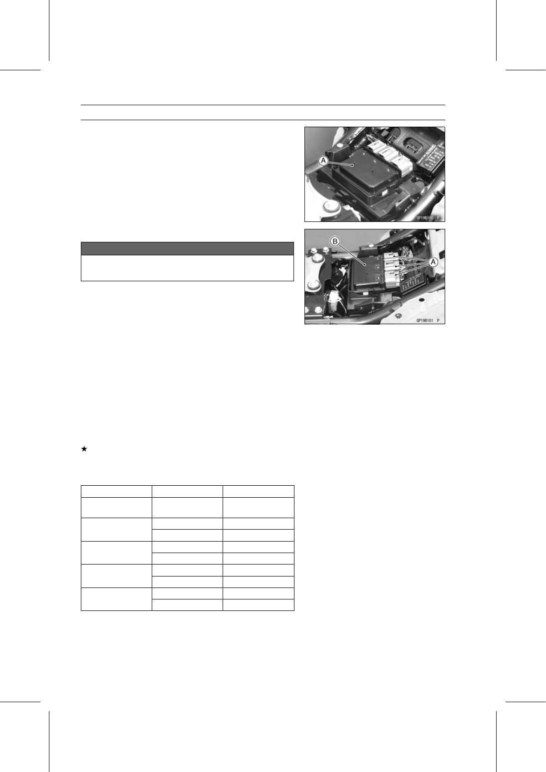
The relay box [A] has relays and diodes. The relays and
diodes can not be removed.

Relay Box Removal

NOTICE

Never drop the relay box especially on a hard sur-
face. Such a shock to the relay box can damage it.

Remove:

Front Seat (see Front Seat Removal in the Frame chap-
ter)

Disconnect the connectors [A] and remove the relay box
[B].

Relay Box Installation

Installation is the reverse of removal.

Run the lead correctly (see Cable, Wire, and Hose Rout-
ing section in the Appendix chapter).

Relay Circuit Inspection

Remove the relay box (see Relay Box Removal).

Check conductivity of the following numbered terminals
by connecting the hand tester and one 12 V battery to the
relay box as shown in the figure (see Relay Box Internal
Circuit in this section).
If the tester does not read as specified, replace the relay
box.

Relay Circuit Inspection (with the battery disconnected)

Tester Connection

Tester Reading (

)

Headlight Circuit
Relay

1-3

7-6

ECU Main Relay

4-5

Not

*

7-8

Fuel Pump Relay

9-10

Not

*

11-16

Starter Circuit Relay

11-12

17-20

Fan Relay

18-19

Not

*

*: The actual reading varies with the hand tester used.

ELECTRICAL SYSTEM 16-79

Relay Box

Relay Circuit Inspection (with the battery connected)

Battery

Connection

(+)

(–)

Tester

Connection

Tester

Reading (

)

Headlight Circuit
Relay

2-11

1-3

0

ECU Main Relay

4-5

7-6

0

Fuel Pump Relay

9-10

7-8

0

Fan Relay

18-19

17-20

0

Battery

Connection

(+)

(–)

Tester Connection

DC 25 V Range

(+)

(–)

Tester

Reading (V)

Starter
Circuit Relay

16-12

11-12

Battery

Voltage

(+): Apply positive lead.

(–): Apply negative lead.

Diode Circuit Inspection

Remove the relay box (see Relay Box Removal).

Check conductivity of the following pairs of terminals (see
Relay Box Internal Circuit in this section).

Diode Circuit Inspection

Tester Connection

1-11, 2-11, 12-13, 12-15, 12-16, 13-14,
13-15

The resistance should be low in one direction and more
than ten times as much in the other direction. If any diode
shows low or high in both directions, the diode is defective
and the relay box must be replaced.

NOTE

The actual meter reading varies with the meter or tester
used and the individual diodes, but generally speaking,
the lower reading should be from zero to one half the
scale.

16-80 ELECTRICAL SYSTEM

Relay Box

Relay Box Internal Circuit

A: Headlight Circuit Relay
B: ECU Main Relay

C: Fuel Pump Relay
D: Starter Circuit Relay

E: Fan Relay

ELECTRICAL SYSTEM 16-81

Fuse

30 A Main Fuse Removal

Remove:

Front Seat (see Front Seat Removal in the Frame chap-
ter)
30 A Main Fuse Cover [A]

Pull out the main fuse [A] from the starter relay with a
needle nose pliers.

Fuse Box Fuse Removal

Remove the front seat (see Front Seat Removal in the
Frame chapter).

Unlock the hook [A] to lift up the lid [B].

Pull the sub fuses [A] straight out from the fuse box with
a needle nose pliers.

Fuse Installation

If a fuse fails during operation, inspect the electrical sys-
tem to determine the cause, and then replace it with a
new fuse of proper amperage.

Install the fuse box fuses on the original position as spec-
ified on the lid.

16-82 ELECTRICAL SYSTEM

Fuse

Fuse Inspection

Remove the fuse (see 30 A Main/Fuse Box/Sub Fuse Re-
moval).

Inspect the fuse element.
If it is blown out, replace the fuse. Before replacing a
blown fuse, always check the amperage in the affected
circuit. If the amperage is equal to or greater than the
fuse rating, check the wiring and related components for
a short circuit.

Housing [A]
Fuse Element [B]
Terminals [C]
Blown Element [D]

NOTICE

When replacing a fuse, be sure the new fuse
matches the specified fuse rating for that circuit.
Installation of a fuse with a higher rating may cause
damage to wiring and components.

APPENDIX 17-1

17

Appendix

Table of Contents

Cable, Wire, and Hose Routing ..............................................................................................

17-2

Troubleshooting Guide ...........................................................................................................

17-54

17-2 APPENDIX

Cable, Wire, and Hose Routing

Left Side Main Harness

APPENDIX 17-3

Cable, Wire, and Hose Routing

1. Meter Lead Connector
2. Horn Lead Connectors
3. Radiator Fan Lead Connector
4. Left Switch Housing Lead Connector
5. Frame Ground
6. Stick Coil #1 Lead Connector
7. Intake Air Pressure Sensor Lead Connector
8. Intake Air Temperature Sensor Lead Connector
9. Battery Positive Lead Connector (ABS Equipped Model)

10. Relay Box Lead Connectors

11. Rear Right Turn Signal Light Lead Connector

12. Rear Left Turn Signal Light Lead Connector
13. Headlight (High) Connector
14. City Light Lead Connector
15. Regulator/Rectifier Lead Connector
16. Front Left Turn Signal Light Lead Connector
17. Bands
18. Purge Valve Lead Connector (CAL Model)
19. Crankshaft Sensor Lead Connector
20. Alternator Lead Connector
21. Oxygen Sensor Lead Connector (Equipped Model)
22. Fuel Injector #1 Lead Connector
23. Subthrottle Valve Actuator Lead Connector
24. Speed Sensor Lead Connector
25. Starter Relay Lead Connector
26. Battery Negative Lead Connector
27. Wheel Rotation Sensor Lead Connector (ABS Equipped Model)
28. Fuse Box
29. License Plate Light Lead Connector
30. Tail/Brake Light Lead Connector
31. Kawasaki Diagnostic System Connector
32. Sidestand Switch Lead Connector
33. Neutral Switch Lead Connector
34. Clamp

17-4 APPENDIX

Cable, Wire, and Hose Routing

Right Side Main Harness

APPENDIX 17-5

Cable, Wire, and Hose Routing

1. ECU Lead Connectors
2. Fuel Pump Lead Connector
3. ABS ECU Lead Connector (ABS Equipped Model)
4. Fuel Injector #2 Lead Connector
5. Ignition Switch Lead Connector
6. Air Switching Valve Lead Connector
7. Vehicle-down Sensor Lead Connector
8. Right Switch Housing Lead Connector
9. Turn Signal Light Relay Lead Connector

10. Rear Brake Light Switch Lead Connector

11. Battery Negative Lead Connector

12. ABS Kawasaki Diagnostic System Connector
13. Subthrottle Sensor Lead Connector
14. Main Throttle Sensor Lead Connector
15. Oil Pressure Switch Lead Connector
16. Clamp
17. Stick Coil #2 Lead Connector
18. Wheel Rotation Sensor Lead Connector (ABS Equipped Model)
19. Water Temperature Sensor Lead Connector
20. Front Right Turn Signal Light Lead Connector
21. Headlight (Low) Connector
22. City Light Lead Connector
23. Bands

17-6 APPENDIX

Cable, Wire, and Hose Routing

APPENDIX 17-7

Cable, Wire, and Hose Routing

1. Right Switch Housing Lead
2. Clamp (Hold the right switch housing lead.)
3. Clamp (Hold the left switch housing lead.)
4. Starter Lockout Switch
5. Left Switch Housing Lead
6. Throttle Cable
7. Brake Hose
8. Guide (Run the throttle cables, right switch housing and ignition switch leads through into the

guide.)

9. Ignition Switch Lead

10. Guide (Run the clutch cable and left switch housing lead through into the guide.)

11. Clutch Cable

12. Guide (Run the clutch cable over the left switch housing lead through into the guide.)
13. Right City Light Connector
14. Headlight (Low) Connector
15. Meter Unit Lead
16. Clamp (Hold the main harness and insert the clamp into the frame.)
17. Headlight (High) Connector
18. Left City Light Connector
19. Main Harness

17-8 APPENDIX

Cable, Wire, and Hose Routing

APPENDIX 17-9

Cable, Wire, and Hose Routing

1. Run the brake hose to front of the right switch housing lead.
2. Front Brake Hose
3. Run the front brake hose to front of the throttle cables.
4. Front Brake Hose
5. Bracket (Hold the front brake hose.)
6. Guide (Run the front brake hose through into the guide.)
7. Bracket (Hold the front brake hose.)
8. Front Brake Hose

17-10 APPENDIX

Cable, Wire, and Hose Routing

APPENDIX 17-11

Cable, Wire, and Hose Routing

1. Throttle Cable (Decelerator)
2. Throttle Cable (Accelerator)
3. Guide (Run the throttle cables, right switch housing and ignition switch leads through into the

guide.)

4. Clutch Cable
5. Guide (Run the clutch cable and left switch housing lead through into the guide.)
6. Guide (Run the clutch cable through into the guide.)
7. Guide (Run the left switch housing lead and throttle cables through into the guide.)
8. Frame Ground Lead
9. Run the throttle cables to over the frame ground lead.

10. Throttle Body Assy

17-12 APPENDIX

Cable, Wire, and Hose Routing

APPENDIX 17-13

Cable, Wire, and Hose Routing

1. Guide (Run the horn lead through into the guide.)
2. Horn Lead
3. Guide (Run the throttle cables through into the guide.)
4. Throttle Cable (Decelerator)
5. Throttle Cable (Accelerator)
6. Regulator/Rectifier
7. Horn
8. Band (Hold the main harness to the upper fairing bracket.)
9. Guide (Run the left switch housing lead through into the guide.)

10. Guide (Run the throttle cables through into the guide.)

11. Left Switch Housing Lead Connector

12. Vehicle-down Sensor
13. Bracket
14. Air Switching Valve
15. Intake Air Pressure Sensor
16. Front Left Turn Signal Light Lead Connector
17. Band (Hold the main harness to the frame pipe.)
18. Crankshaft Sensor Lead Connector
19. Oxygen Sensor Lead Connector (Equipped Model)
20. Alternator Lead Connector
21. Guide (Run the crankshaft sensor lead, oxygen sensor lead and alternator lead through into the

guide.)

22. Band (Hold the crankshaft sensor lead, oxygen sensor lead and alternator lead together with

the water pipe.)

23. Clamp (Hold the crankshaft sensor lead, oxygen sensor lead and alternator lead.)
24. Guide (Run the main harness into the guide.)
25. Main Harness
26. Band (Hold the main harness to the frame pipe.)
27. Band (Hold the main harness to the frame.)

17-14 APPENDIX

Cable, Wire, and Hose Routing

APPENDIX 17-15

Cable, Wire, and Hose Routing

1. Vehicle-down Sensor Lead
2. Clamp (Hold the right switch housing lead and fix the clamp into the frame.)
3. Ignition Switch Lead
4. Clamp (Hold the ignition switch lead and front right turn signal light lead and fix the clamp into

the upper fairing bracket.)

5. Band (Hold the front right turn signal light lead together with the upper fairing bracket.)
6. Front Right Turn Signal Light Lead Connector
7. Right Switch Housing Lead
8. Band (Hold the water temperature sensor lead together with the frame.)
9. Hold the main harness to the frame with the band, and cut the band excess length after tying it.

10. Ignition Switch Lead Connector

11. Ignition Switch Lead Connector (Hold the connector to the bracket on the frame.)

12. Hold the main harness to the frame with the band, and cut the band excess length after tying it.
13. Water Temperature Sensor
14. Run the oil pressure switch lead to outside of the clutch cable.
15. Oil Pressure Switch Lead
16. Band (Hold the oil pressure switch lead with the bracket.)
17. Clamp (Hold the oil pressure switch lead.)
18. Run the ignition switch lead under the main harness.

17-16 APPENDIX

Cable, Wire, and Hose Routing

APPENDIX 17-17

Cable, Wire, and Hose Routing

1. Guide (Run the sidestand switch lead, neutral switch lead and speed sensor lead through into

the guide.)

2. Drain Hose
3. Speed Sensor Lead
4. Neutral Switch Lead
5. Sidestand Switch Lead
6. Clamp (Hold the neutral switch lead and speed sensor lead.)
7. Clamp (Hold the neutral switch lead and speed sensor lead.)
8. Guide (Run the sidestand switch lead and drain hose through into the guide.)
9. Sidestand Switch

17-18 APPENDIX

Cable, Wire, and Hose Routing

APPENDIX 17-19

Cable, Wire, and Hose Routing

1. Fuel Injector #2
2. Fuel Pump Lead Connector
3. Air Switching Valve Hose
4. Guide (Run the turn signal relay lead through into the guide.)
5. Turn Signal Relay
6. License Plate Light Lead Connector
7. Tail/Brake Light Lead Connector
8. Kawasaki Diagnostic System Connector
9. Fuel Injector #1

10. Subthrottle Valve Actuator Lead Connector

11. Rear Right Turn Signal Light Lead Connector

12. Rear Left Turn Signal Light Lead Connector
13. Band (Hold the main harness to the bracket.)
14. Band (Hold the license plate light lead, tail/brake light lead, rear right turn signal light lead and

rear left turn signal light lead to the bracket.)

15. Bracket
16. Clamp (Hold the main harness to the rear fender.)
17. Battery Negative Cable
18. ECU Lead Connectors
19. Hold the main harness to the frame with the band, and cut the band excess length after tying it.
20. Starter Motor Cable
21. Intake Air Temperature Sensor Lead Connector
22. Starter Relay Lead Connector
23. Battery Positive Cable
24. Relay Box
25. Fuse Box

17-20 APPENDIX

Cable, Wire, and Hose Routing

APPENDIX 17-21

Cable, Wire, and Hose Routing

1. Turn Signal Relay
2. Main Harness
3. Band (Hold the main harness to the frame.)
4. Band (Hold the main harness, battery negative cable and starter motor cable. Do not hold them

to the frame.)

5. Subthrottle Sensor
6. Main Throttle Sensor
7. Rear Fender
8. Rear Brake Light Switch Lead
9. Engine Ground Terminal

10. Starter Motor Cable Terminal

11. Band

12. Run the rear brake light switch lead through the hole on the rear fender.
13. Band (Hold the rear brake light switch lead at the white mark on the lead.)
14. Clamp (Hold the rear brake light switch lead.)
15. Rear Brake Light Switch
16. Band

17-22 APPENDIX

Cable, Wire, and Hose Routing

APPENDIX 17-23

Cable, Wire, and Hose Routing

1. Rear Right Turn Signal Light Lead Connector
2. Rear Left Turn Signal Light Lead Connector
3. License Plate Light Lead Connector
4. Tail/Brake Light Lead Connector
5. Run the license plate light lead, rear left turn signal light lead and rear right turn signal light lead

through into the guide.

6. Cover
7. Tail/Brake Light Lead
8. Clamp (Hold the tail/brake light lead to the bracket.)
9. Guide (Run the main harness over the guide.)

10. Band (Hold the main harness with the bracket.)

11. Clamp (Hold the license plate light lead, rear left turn signal light lead, rear right turn signal light

lead and tail/brake light lead to the bracket.)

12. Kawasaki Diagnostic System Connector
13. Guide (Run the license plate light lead, rear left turn signal light lead and rear right turn signal

light lead through into the guide.)

14. Clamp (Hold the license plate light lead, rear left turn signal light lead, rear right turn signal light

lead, tail/brake light lead and main harness to the rear fender.)

15. Rear Right Turn Signal Light Lead
16. Run the license plate light lead, rear left turn signal light lead and rear right turn signal light lead

into the hole of the rear fender.

17. Trim (Run the license plate light lead and rear right turn signal light lead through the trim.)
18. License Plate Light Lead
19. Rear Left Turn Signal Light Lead

17-24 APPENDIX

Cable, Wire, and Hose Routing

APPENDIX 17-25

Cable, Wire, and Hose Routing

1. Fuel Tank Breather Hose
2. Guide (Run the fuel tank breather hose through into the guide.)
3. Drain Hose
4. Clamp (Hold the fuel tank drain hose with the frame.)
5. Adjusting Screw
6. Sidestand Switch Lead Connector
7. Fuel Tank Drain Hose
8. Run the fuel tank drain hose under the air cleaner housing.
9. Engine Bracket

10. Sidestand Switch Lead

11. Guide (Run the fuel tank drain hose and sidestand switch lead through into the guide.)

12. Engine Bracket
13. Clamp (Hold the fuel tank drain hose with the sidestand switch.)

17-26 APPENDIX

Cable, Wire, and Hose Routing

APPENDIX 17-27

Cable, Wire, and Hose Routing

1. Clamp (Hold the left city light lead and headlight (high) lead and fix the clamp into the upper

fairing bracket.)

2. Left City Light Lead
3. Cover
4. Headlight (High) Lead
5. Band (Hold the left city light lead and headlight (high) lead to the upper fairing bracket.)
6. Clamp (Hold the right city light lead and headlight (low) lead and fix the clamp to the meter.)
7. Clamp (Hold the leads.)
8. Cover
9. Right City Light Lead

10. Headlight (Low) Lead

11. Band (Hold the right city light lead and headlight (low) lead to the frame.)

12. Radiator Fan Connector
13. Run the leads to inside of the main harness.
14. Battery Negative Cable
15. Main Harness
16. Starter Motor Cable
17. Battery Positive Cable
18. Main Harness

17-28 APPENDIX

Cable, Wire, and Hose Routing

ABS Equipped Models

APPENDIX 17-29

Cable, Wire, and Hose Routing

1. ABS Hydraulic Unit
2. Damper (Hold the brake pipes to bracket on frame.)
3. Brake Pipe (ABS Hydraulic Unit

Front Caliper)

4. Brake Pipe (Front Master Cylinder

ABS Hydraulic Unit)

5. Front Wheel Rotation Sensor Connector
6. Clamp (Hold the brake pipes.)
7. Ignition Switch Lead
8. Guide (Run the leads.)
9. Front Right Turn Signal Light Lead

10. Clamp (Hold the front right turn signal light lead, wheel rotation sensor lead and ignition switch

lead and insert the clamp to the thermostat housing.)

11. Main Harness

12. Band (Hold the water temperature sensor lead.)
13. Throttle Cable
14. Clutch Cable
15. Guide (Run the leads.)
16. Front Brake Hose
17. Front Brake Hose
18. Band (Hold the front wheel rotation sensor lead.)
19. Clamp (Hold the front brake hose.)
20. Front Wheel Rotation Sensor Lead
21. Clamp (Hold the front wheel rotation sensor lead and brake hose.)
22. Clamp (Hold the front wheel rotation sensor lead and brake hose.)
23. Clamp (Hold the front wheel rotation sensor lead and brake hose to front fender.)
24. Clamp (Hold the front wheel rotation sensor lead.)
25. Front Wheel Rotation Sensor

17-30 APPENDIX

Cable, Wire, and Hose Routing

ABS Equipped Models

APPENDIX 17-31

Cable, Wire, and Hose Routing

1. ECU Lead Connectors
2. ECU Lead Connectors
3. Wheel Rotation Sensor Lead Connector
4. ABS Hydraulic Unit
5. Damper (Hold the brake pipes to bracket on frame.)
6. Brake Pipe (ABS Hydraulic Unit

Rear Caliper)

7. Brake Pipe (ABS Hydraulic Unit

Rear Master Cylinder

)

8. Rear Brake Switch Connector
9. Run the rear wheel rotation sensor lead and rear brake switch lead into the hole of the rear

fender.

10. Damper (Hold the brake pipes to bracket on frame.)

11. ABS Kawasaki Diagnostic System Connector

12. Hold the ABS Kawasaki Diagnostic System Connector to the fuel tank bracket.

17-32 APPENDIX

Cable, Wire, and Hose Routing

ABS Equipped Models

APPENDIX 17-33

Cable, Wire, and Hose Routing

1. Rear Wheel Rotation Sensor Lead
2. Clamp (Hold the rear wheel rotation sensor lead to the swingarm.)
3. Run the rear wheel rotation sensor lead and rear brake switch lead into the hole of the rear

fender.

4. Band (Hold the rear wheel rotation sensor lead and rear brake switch lead to the rear fender.)
5. Guide (Run the rear brake hose into the guide.)
6. Clamp (Hold the rear wheel rotation sensor lead and rear brake hose.)
7. Rear Wheel Rotation Sensor
8. Rear Brake Hose
9. Clamp (Hold the rear wheel rotation sensor lead and rear brake hose.)

10. Guide (Run the rear wheel rotation sensor lead and rear brake hose into the guide.)

11. Clamp (Hold the rear wheel rotation sensor lead.)

12. Clamp (Hold the rear brake hose.)
13. Rear Brake Switch Lead
14. Clamp (Hold the rear wheel rotation sensor lead and rear brake switch lead.)
15. Clamp (Hold the rear brake hose.)

17-34 APPENDIX

Cable, Wire, and Hose Routing

1. Stick Coil #1 Lead Connector
2. Stick Coil #2 Lead Connector

APPENDIX 17-35

Cable, Wire, and Hose Routing

CAL Model

1. Purge Valve
2. Main Harness
3. Fuel Tank Drain Hose
4. Guide (Run the hose into the guide.)
5. Guide (Run the hose into the guide.)
6. Canister

17-36 APPENDIX

Cable, Wire, and Hose Routing

GPS Unit Equipped Models

APPENDIX 17-37

Cable, Wire, and Hose Routing

1. Right City Light Connector
2. Headlight (Low) Connector
3. Upper Fairing Bracket
4. GPS Unit Lead Connector
5. To Meter
6. Headlight (High) Connector
7. Left City Light Connector
8. GPS Unit
9. Band (Hold the right city light lead, headlight (low) lead and GPS unit lead to the upper fairing

bracket.)

10. Clamp (Hold the main harness and GPS unit lead to the meter.)

11. Guide (Run the main harness and GPS unit lead to the upper fairing bracket.)

17-38 APPENDIX

Cable, Wire, and Hose Routing

GPS Unit Equipped Models

APPENDIX 17-39

Cable, Wire, and Hose Routing

1. Band (Hold the main harness to the upper fairing bracket.)
2. Siren
3. Band (Hold the main harness to the frame.)
4. Main Harness

17-40 APPENDIX

Cable, Wire, and Hose Routing

APPENDIX 17-41

Cable, Wire, and Hose Routing

1. Thermostat
2. Radiator Cap
3. Clamp Screw
4. 90°
5. Section B-B
6. Upper
7. 45°
8. Viewed A
9. Align the white paint mark on the hose with the projection mark on the fitting.

10. Viewed C

11. Cylinder Head

12. Radiator
13. Install the hose so that its end covers the white paint mark on the pipe.
14. Cylinder
15. Align the white paint mark on the hose with the projection mark on the fitting.
16. Viewed D

17-42 APPENDIX

Cable, Wire, and Hose Routing

APPENDIX 17-43

Cable, Wire, and Hose Routing

1. Reserve Tank Overflow Hose
2. Clamps
3. Radiator Cap
4. Align the white paint mark on the hose with the hole of the reserve tank.
5. Reserve Tank Hose
6. Reserve Tank
7. Run the reserve tank overflow hose under the reserve tank hose.
8. Bracket
9. Run the reserve tank overflow hose into the bracket.

17-44 APPENDIX

Cable, Wire, and Hose Routing

APPENDIX 17-45

Cable, Wire, and Hose Routing

1. Vehicle-down Sensor
2. Intake Air Pressure Sensor
3. Damper
4. Clamps
5. Vacuum Hose
6. Air Switching Valve Hose
7. Air Switching Valve
8. Clamp
9. Install the hose so that its white mark side faces the air switching valve.

17-46 APPENDIX

Cable, Wire, and Hose Routing

APPENDIX 17-47

Cable, Wire, and Hose Routing

1. Front Master Cylinder
2. Front Brake Hose
3. Bracket
4. Guide
5. Front Brake Caliper
6. Rear Brake Reservoir Tank
7. Rear Brake Caliper
8. Clamp
9. Clamp

10. Clamp

11. Rear Master Cylinder

12. Viewed A

17-48 APPENDIX

Cable, Wire, and Hose Routing

ABS Equipped Models

APPENDIX 17-49

Cable, Wire, and Hose Routing

1. Front Master Cylinder
2. ABS Hydraulic Unit
3. Brake Pipe (ABS Hydraulic Unit

Front Caliper)

4. Clamp (Hold the brake pipes.)
5. Bracket (Hold the brake pipes.)
6. Brake Hose (Front Master Cylinder

ABS Hydraulic Unit)

7. Brake Hose (ABS Hydraulic Unit

Front Caliper)

8. Brake Pipe (Front Master Cylinder

ABS Hydraulic Unit)

9. Damper (Hold the brake pipes.)

10. Brake Hose Bracket

11. Clamp (Hold the front wheel rotation sensor lead.)

12. Front Brake Caliper
13. Front Wheel Rotation Sensor
14. Guide
15. Band
16. Bracket
17. Guide
18. Clamps (Hold the front wheel rotation sensor lead to the brake hose with the clamps at the white

mark on the lead.)

17-50 APPENDIX

Cable, Wire, and Hose Routing

ABS Equipped Models

APPENDIX 17-51

Cable, Wire, and Hose Routing

1. Clamp (Hold the rear wheel rotation sensor lead to the brake hose with the clamp at the white

mark on the lead.)

2. ABS Hydraulic Unit
3. Bracket (Hold the brake hoses.)
4. Clamp (Hold the brake pipes.)
5. Rear Brake Reservoir Tank
6. Brake Hose (Rear Brake Reservoir Tank

Rear Master Cylinder)

7. Clamp (Hold the rear wheel rotation sensor lead.)
8. Brake Hose (Rear Master Cylinder

ABS Hydraulic Unit)

9. Clamp (Hold the brake pipes.)

10. Damper (Hold the brake pipes.)

11. Rear Wheel Rotation Sensor

12. Rear Brake Caliper
13. Clamp (Hold the brake hose.)
14. Clamp (Hold the brake hose.)
15. Guide (Run the rear wheel rotation sensor lead )
16. Brake Hose (ABS Hydraulic Unit

Rear Caliper)

17. Clamp (Hold the brake hose.)
18. Rear Master Cylinder

17-52 APPENDIX

Cable, Wire, and Hose Routing

CAL Model

APPENDIX 17-53

Cable, Wire, and Hose Routing

1. Clamp (Face the tabs of the clamp in direction.)
2. Green Mark
3. Hose (Green)
4. Vacuum Hose
5. Run the hose (Green) over the vacuum hose and throttle cable.
6. Throttle Cable
7. Throttle Body Assy
8. Purge Valve
9. Hose (Green)

10. Clamps (Hold the hoses.)

11. Fuel Tank

12. Blue Mark
13. Hose (Blue)
14. Clamp (Hold the hose.)
15. Bracket
16. Green Mark
17. Clamp (Hold the hose.)
18. Canister

17-54 APPENDIX

Troubleshooting Guide

NOTE

Refer to the Fuel System (DFI) chapter for
most of DFI trouble shooting guide.

This is not an exhaustive list, giving every
possible cause for each problem listed. It
is meant simply as a rough guide to assist
the troubleshooting for some of the more
common difficulties.

Engine Doesn’t Start, Starting

Difficulty:

Starter motor not rotating:

Starter lockout switch or neutral switch trou-

ble

Starter motor trouble
Battery voltage low
Starter relay not contacting or operating
Starter button not contacting
Wiring open or shorted
Ignition switch trouble
Engine stop switch trouble
Fuse blown

Starter motor rotating but engine doesn’t
turn over:

Starter clutch trouble
Vehicle-down sensor (DFI) coming off

Engine won’t turn over:

Valve seizure
Valve lifter seizure
Cylinder, piston seizure
Crankshaft seizure
Connecting rod small end seizure
Connecting rod big end seizure
Transmission gear or bearing seizure
Camshaft seizure
Starter idle gear seizure

No fuel flow:

No fuel in tank
Fuel pump trouble
Fuel tank air vent obstructed
Fuel filter clogged
Fuel line clogged

Engine flooded:

Clean spark plug and adjust plug gap
Starting technique faulty
(When flooded, do not crank the engine with
the throttle fully opened. This promotes
engine flood because more fuel is supplied
automatically by DFI.)

No spark; spark weak:

Vehicle-down sensor (DFI) coming off
Ignition switch not ON
Engine stop switch turned to stop position
Clutch lever not pulled in or gear not in neu-

tral

Battery voltage low

Spark plug dirty, broken, or gap malad-

justed

Stick coil shorted or not in good contact
Stick coil trouble
Spark plug incorrect
IC igniter in ECU trouble
Neutral, starter lockout, or side stand switch

trouble

Crankshaft sensor trouble
Ignition switch or engine stop switch

shorted

Wiring shorted or open
Fuse blown

Fuel/air mixture incorrect:

Bypass screw and/or idle adjusting screw

maladjusted

Air passage clogged
Air cleaner clogged, poorly sealed, or miss-

ing

Compression Low:

Spark plug loose
Cylinder head not sufficiently tightened

down

No valve clearance
Cylinder, piston worn
Piston ring bad (worn, weak, broken, or

sticking)

Piston ring/groove clearance excessive
Cylinder head gasket damaged
Cylinder head warped
Valve spring broken or weak
Valve not seating properly (valve bent,

worn, or carbon accumulation on the
seating surface)

Poor Running at Low Speed:

Spark weak:

Battery voltage low
Spark plug dirty, broken, or maladjusted
Stick coil wiring trouble
Stick coil not in good contact
Spark plug incorrect
IC igniter in ECU trouble
Crankshaft sensor trouble
Stick coil trouble

Fuel/air mixture incorrect:

Bypass screw maladjusted
Air passage clogged
Air cleaner clogged, poorly sealed, or miss-

ing

Fuel tank air vent obstructed
Fuel pump trouble
Throttle body assy holder loose
Air cleaner duct loose

Compression low:

Spark plug loose

APPENDIX 17-55

Troubleshooting Guide

Cylinder head not sufficiently tightened

down

No valve clearance
Cylinder, piston worn
Piston ring bad (worn, weak, broken, or

sticking)

Piston ring/groove clearance excessive
Cylinder head warped
Cylinder head gasket damaged
Valve spring broken or weak
Valve not seating properly (valve bent,

worn, or carbon accumulation on the
seating surface)

Other:

IC igniter in ECU trouble
Throttle body assy not synchronizing
Engine oil viscosity too high
Drive train trouble
Brake dragging
Air suction valve trouble
Air switching valve trouble
Engine overheating
Clutch slipping

Poor Running or No Power at High

Speed:

Firing incorrect:

Spark plug dirty, broken, or maladjusted
Stick coil wiring trouble
Stick coil not in good contact
Spark plug incorrect
Camshaft position trouble
IC igniter in ECU trouble
Crankshaft sensor trouble
Stick coil trouble

Fuel/air mixture incorrect:

Air cleaner clogged, poorly sealed, or miss-

ing

Air cleaner O-ring damaged
Air cleaner duct loose
Water or foreign matter in fuel
Throttle body assy holder loose
Fuel to injector insufficient (DFI)
Fuel tank air vent obstructed
Fuel line clogged
Fuel pump trouble

Compression low:

Spark plug loose
Cylinder head not sufficiently tightened

down

No valve clearance
Cylinder, piston worn
Piston ring bad (worn, weak, broken, or

sticking)

Piston ring/groove clearance excessive
Cylinder head gasket damaged
Cylinder head warped

Valve spring broken or weak
Valve not seating properly (valve bent,

worn, or carbon accumulation on the
seating surface)

Knocking:

Carbon built up in combustion chamber
Fuel poor quality or incorrect
Spark plug incorrect
IC igniter in ECU trouble
Crankshaft sensor trouble

Miscellaneous:

Throttle valve won’t fully open
Brake dragging
Clutch slipping
Engine overheating
Engine oil level too high
Engine oil viscosity too high
Drive train trouble
Air suction valve trouble
Air switching valve trouble
Catalytic converter melt down due to muffler

overheating (KLEEN)

Overheating:

Firing incorrect:

Spark plug dirty, broken, or maladjusted
Spark plug incorrect
IC igniter in ECU trouble

Muffler overheating:

For KLEEN, do not run the engine even if

with only one cylinder misfiring or poor
running (Request the nearest service fa-
cility to correct it)

For KLEEN, do not push-start with a dead

battery (Connect another full-charged
battery with jumper cables, and start the
engine using the electric starter)

For KLEEN, do not start the engine under

misfire due to spark plug fouling or poor
connection of the stick coil

For KLEEN, do not coast the motorcycle

with the ignition switch off (Turn the igni-
tion switch ON and run the engine)

IC igniter in ECU trouble

Fuel/air mixture incorrect:

Throttle body assy holder loose
Air cleaner duct loose
Air cleaner poorly sealed, or missing
Air cleaner O-ring damaged
Air cleaner clogged

Compression high:

Carbon built up in combustion chamber

Engine load faulty:

Clutch slipping
Engine oil level too high
Engine oil viscosity too high
Drive train trouble

17-56 APPENDIX

Troubleshooting Guide

Brake dragging

Lubrication inadequate:

Engine oil level too low
Engine oil poor quality or incorrect

Water temperature warning indicator light
incorrect:

Meter unit trouble
Water temperature sensor broken

Coolant incorrect:

Coolant level too low
Coolant deteriorated
Wrong coolant mixed ratio

Cooling system component incorrect:

Radiator fin damaged
Radiator clogged
Thermostat trouble
Radiator cap trouble
Radiator fan relay trouble
Fan motor broken
Fan blade damaged
Water pump not turning
Water pump impeller damaged

Over Cooling:

Cooling system component incorrect:

Radiator fan relay trouble
Thermostat trouble
Water temperature sensor broken

Clutch Operation Faulty:

Clutch slipping:

Friction plate worn or warped
Steel plate worn or warped
Clutch spring broken or weak
Clutch hub or housing unevenly worn
No clutch lever play
Clutch inner cable trouble
Clutch release mechanism trouble

Clutch not disengaging properly:

Clutch plate warped or too rough
Clutch spring compression uneven
Engine oil deteriorated
Engine oil viscosity too high
Engine oil level too high
Clutch housing frozen on drive shaft
Clutch hub nut loose
Clutch hub spline damaged
Clutch friction plate installed wrong
Clutch lever play excessive
Clutch release mechanism trouble

Gear Shifting Faulty:

Doesn’t go into gear; shift pedal doesn’t
return:

Clutch not disengaging
Shift fork bent or seized

Gear stuck on the shaft
Gear positioning lever binding
Shift return spring weak or broken
Shift return spring pin loose
Shift mechanism arm spring broken
Shift mechanism arm broken
Shift pawl broken

Jumps out of gear:

Shift fork ear worn, bent
Gear groove worn
Gear dogs and/or dog holes worn
Shift drum groove worn
Gear positioning lever spring weak or bro-

ken

Shift fork guide pin worn
Drive shaft, output shaft, and/or gear

splines worn

Overshifts:

Gear positioning lever spring weak or bro-

ken

Shift mechanism arm spring broken

Abnormal Engine Noise:

Knocking:

IC igniter in ECU trouble
Carbon built up in combustion chamber
Fuel poor quality or incorrect
Spark plug incorrect
Overheating

Piston slap:

Cylinder/piston clearance excessive
Cylinder, piston worn
Connecting rod bent
Piston pin, piston pin hole worn

Valve noise:

Valve clearance incorrect
Valve spring broken or weak
Camshaft bearing worn
Valve lifter worn

Other noise:

Connecting rod small end clearance exces-

sive

Connecting rod big end clearance exces-

sive

Piston ring/groove clearance excessive
Piston ring worn, broken, or stuck
Piston ring groove worn
Piston seizure, damage
Cylinder head gasket leaking
Exhaust pipe leaking at cylinder head con-

nection

Crankshaft runout excessive
Engine mount loose
Crankshaft bearing worn
Camshaft chain tensioner trouble
Camshaft chain, sprocket, guide worn
Air suction valve damaged

APPENDIX 17-57

Troubleshooting Guide

Air switching valve damaged
Alternator rotor loose
Catalytic converter melt down due to muffler

overheating (KLEEN)

Abnormal Drive Train Noise:

Clutch noise:

Clutch housing/friction plate clearance ex-

cessive

Clutch housing gear worn
Wrong installation of outside friction plate

Transmission noise:

Bearings worn
Transmission gear worn or chipped
Metal chips jammed in gear teeth
Engine oil insufficient

Drive line noise:

Drive chain adjusted improperly
Drive chain worn
Rear and/or engine sprocket worn
Chain lubrication insufficient
Rear wheel misaligned

Abnormal Frame Noise:

Front fork noise:

Oil insufficient or too thin
Spring weak or broken

Rear shock absorber noise:

Shock absorber damaged

Disc brake noise:

Pad installed incorrectly
Pad surface glazed
Disc warped
Caliper trouble

Other noise:

Bracket, nut, bolt, etc.

not properly

mounted or tightened

Oil Pressure Warning Light Goes On:

Engine oil pump damaged
Engine oil screen clogged
Engine oil filter clogged
Engine oil level too low
Engine oil viscosity too low
Camshaft bearing worn
Crankshaft bearing worn
Oil pressure switch damaged
Wiring faulty
Relief valve stuck open
O-ring at the oil passage in the crankcase

damaged

Exhaust Smokes Excessively:

White smoke:

Piston oil ring worn
Cylinder worn

Valve oil seal damaged
Valve guide worn
Engine oil level too high

Black smoke:

Air cleaner clogged

Brown smoke:

Air cleaner duct loose
Air cleaner O-ring damaged
Air cleaner poorly sealed or missing

Handling and/or Stability

Unsatisfactory:

Handlebar hard to turn:

Cable routing incorrect
Hose routing incorrect
Wiring routing incorrect
Steering stem nut too tight
Steering stem bearing damaged
Steering stem bearing lubrication inade-

quate

Steering stem bent
Tire air pressure too low

Handlebar shakes or excessively vibrates:

Tire worn
Swingarm pivot bearing worn
Rim warped, or not balanced
Wheel bearing worn
Handlebar holder bolt loose
Steering stem nut loose
Front, rear axle runout excessive
Engine mounting bolt loose

Handlebar pulls to one side:

Frame bent
Wheel misalignment
Swingarm bent or twisted
Swingarm pivot shaft runout excessive
Steering maladjusted
Front fork bent
Right and left front fork oil level uneven

Shock absorption unsatisfactory:

(Too hard)
Front fork oil excessive
Front fork oil viscosity too high
Rear shock absorber adjustment too hard
Tire air pressure too high
Front fork bent
(Too soft)
Tire air pressure too low
Front fork oil insufficient and/or leaking
Front fork oil viscosity too low
Rear shock adjustment too soft
Front fork, rear shock absorber spring weak
Rear shock absorber oil leaking

Brake Doesn’t Hold:

Air in the brake line
Pad or disc worn

17-58 APPENDIX

Troubleshooting Guide

Brake fluid leakage
Disc warped
Contaminated pad
Brake fluid deteriorated
Primary or secondary cup damaged in master

cylinder

Master cylinder scratched inside

Battery Trouble:

Battery discharged:

Charge insufficient
Battery faulty (too low terminal voltage)

Battery cable making poor contact
Load excessive (e.g., bulb of excessive

wattage)

Ignition switch trouble
Alternator trouble
Wiring faulty
Regulator/rectifier trouble

Battery overcharged:

Alternator trouble
Regulator/rectifier trouble
Battery faulty

MODEL APPLICATION

Year

Model

Beginning Frame No.

2013

EX300AD

JKAEX8A1

DDA00001

JKAEX300AADA00001

2013

EX300BD

JKAEX8B1

DDA00001

JKAEX300ABDA00001

:This digit in the frame number changes from one machine to another.

Part No.99924-1460-01

Printed in Japan


Content      ..     16      17      18