Kawasaki Ninja 300 / Ninja 300 ABS Motorcycle. Service Manual (2013) - page 14
 

  Index      Manuals     Kawasaki Ninja 300 / Ninja 300 ABS Motorcycle. Service Manual (2013)


Search            copyright infringement  


Content      ..     12      13      14      15     ..


Kawasaki Ninja 300 / Ninja 300 ABS Motorcycle. Service Manual (2013) - page 14


12-60 BRAKES

Anti-Lock Brake System (Equipped Models)

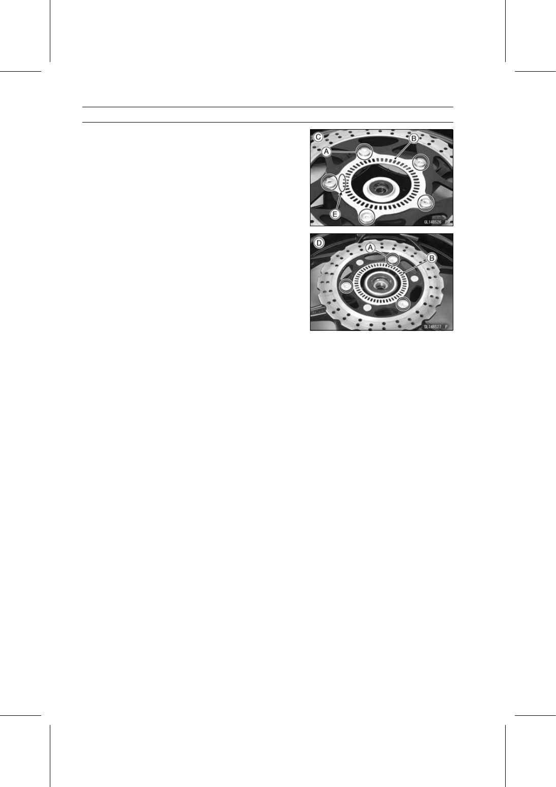
If necessary, replace the sensor rotor as follows.

Remove:

Wheels (see Front/Rear Wheel Removal in the
Wheels/Tires chapter)
Brake Disc Mounting Bolts [A]
Sensor Rotor [B]
Front Wheel [C]
Rear Wheel [D]

The rear sensor rotor can not be removed from the rear
brake disc.

Install the front sensor rotor with “577” mark [E] side facing
out.

Install the removed parts (see appropriate chapters).

Fuse Removal

Refer to the Fuse Box Fuse Removal in the Electrical Sys-
tem chapter.

Fuse Installation

If a fuse fails during operation, inspect the electrical sys-
tem to determine the cause, and then replace it with a
new fuse of proper amperage (see Fuse Installation in the
Electrical System chapter).

Fuse Inspection

Refer to the Fuse Inspection in the Electrical System
chapter.

SUSPENSION 13-1

13

Suspension

Table of Contents

Exploded View........................................................................................................................

13-2

Specifications .........................................................................................................................

13-6

Special Tools ..........................................................................................................................

13-7

Front Fork ...............................................................................................................................

13-8

Front Fork Removal (Each Fork Leg) ...............................................................................

13-8

Front Fork Installation (Each Fork Leg) ............................................................................

13-8

Front Fork Oil Change ......................................................................................................

13-8

Front Fork Disassembly ....................................................................................................

13-10

Front Fork Assembly.........................................................................................................

13-11

Inner Tube, Outer Tube Inspection ...................................................................................

13-12

Dust Seal Inspection .........................................................................................................

13-13

Fork Spring Tension Inspection.........................................................................................

13-13

Rear Shock Absorber .............................................................................................................

13-14

Spring Preload Adjustment ...............................................................................................

13-14

Rear Shock Absorber Removal ........................................................................................

13-14

Rear Shock Absorber Installation .....................................................................................

13-15

Rear Shock Absorber Inspection ......................................................................................

13-15

Rear Shock Absorber Scrapping ......................................................................................

13-16

Swingarm................................................................................................................................

13-17

Swingarm Removal...........................................................................................................

13-17

Swingarm Installation........................................................................................................

13-17

Swingarm Bearing Removal .............................................................................................

13-18

Swingarm Bearing Installation ..........................................................................................

13-18

Swingarm Bearing, Sleeve Inspection ..............................................................................

13-19

Swingarm Bearing Lubrication ..........................................................................................

13-19

Tie-Rod, Rocker Arm..............................................................................................................

13-20

Tie-Rod Removal ..............................................................................................................

13-20

Tie-Rod Installation ...........................................................................................................

13-20

Rocker Arm Removal........................................................................................................

13-20

Rocker Arm Installation.....................................................................................................

13-21

Tie-Rod, Rocker Arm Bushing Inspection.........................................................................

13-21

Tie-Rod, Rocker Arm Sleeve Inspection...........................................................................

13-21

13-2 SUSPENSION

Exploded View

SUSPENSION 13-3

Exploded View

Torque

No.

Fastener

N·m

kgf·m

ft·lb

Remarks

1

Front Fork Upper Clamp Bolts

20

2.0

15

2

Front Fork Lower Clamp Bolts

30

3.1

22

3

Front Fork Bottom Allen Bolts

20

2.0

15

AD

AD: Apply adhesive.

G: Apply grease.

R: Replacement Parts

13-4 SUSPENSION

Exploded View

SUSPENSION 13-5

Exploded View

Torque

No.

Fastener

N·m

kgf·m

ft·lb

Remarks

1

Rear Shock Absorber Nuts

59

6.0

44

R

2

Swingarm Pivot Shaft Nut

98

10.0

72

3

Rocker Arm Nut

59

6.0

44

R

4

Tie-Rod Nuts

59

6.0

44

R

G: Apply grease.

R: Replacement Parts

13-6 SUSPENSION

Specifications

Item

Standard

Front Fork (Per One Unit)

Fork Inner Tube Diameter

37 mm (1.5 in.)

Air Pressure

Atmospheric pressure (Non-adjustable)

Rebound Damper Setting

Non-adjustable

Fork Spring Preload Setting

Non-adjustable

Fork Oil:

Recommended Oil

SHOWA SS-8 or equivalent

Amount

Approx. 316 mL (10.7 US oz.) (when changing oil)
372 ±2.5 mL (12.6 ±0.085 US oz.) (after disassembly and
completely dry)

Fork Oil Level

100 ±2 mm (3.94 ±0.08 in.) (fully compressed, without fork
spring, below from the top of the inner tube)

Fork Spring Free Length

420.5 mm (16.56 in.) (Service Limit: 412 mm (16.22 in.))

Rear Shock Absorber

Rebound Damper Setting

Non-adjustable

Spring Preload Setting

2nd position (Adjustable range: 1st

5th position)

Gas Pressure

980 kPa (10 kgf/cm², 142 psi, Non-adjustable)

SUSPENSION 13-7

Special Tools

Fork Cylinder Holder Handle:
57001-183

Fork Cylinder Holder Adapter:
57001-1057

Oil Seal & Bearing Remover:
57001-1058

Bearing Driver Set:
57001-1129

Fork Outer Tube Weight:
57001-1218

Front Fork Oil Seal Driver:
57001-1219

Jack:
57001-1238

Fork Oil Level Gauge:
57001-1290

Jack Attachment:
57001-1608

13-8 SUSPENSION

Front Fork

Front Fork Removal (Each Fork Leg)

Remove:

Lower Fairings (see Lower Fairing Removal in the Frame
chapter)
Front Wheel (see Front Wheel Removal in the
Wheels/Tires chapter)
Front Fender (see Front Fender Removal in the Frame
chapter)
Bolts [A] (Both Sides)
Bracket [B]

Remove the handlebar (see Handlebar Removal in the
Steering chapter).

Loosen the front fork upper [A] and lower [B] clamp bolts.

With a twisting motion, remove the fork leg down and out.

Front Fork Installation (Each Fork Leg)

Insert the fork leg [A] through the steering stem and steer-
ing stem head.

Adjust the fork height [B] measured at the edge of the slit
[C] on the steering stem head is approximate 12 mm (0.47
in.).

Tighten:

Torque - Front Fork Upper Clamp Bolts [D]: 20 N·m (2.0

kgf·m, 15 ft·lb)

Front Fork Lower Clamp Bolts [E]: 30 N·m (3.1

kgf·m, 22 ft·lb)

Install the removed parts (see appropriate chapters).

Front Fork Oil Change

Remove:

Front Fork (see Front Fork Removal)
Snap Ring [A] (see Front Fork Disassembly)
Top Plug [B] with O-ring [C]
Collar [D]
Fork Spring Seat [E]
Fork Spring [F]

SUSPENSION 13-9

Front Fork

Compress [A] the fork [B] upside down to draw out the oil
into the suitable container [C].

Hold the fork tube upright, pour in the type and amount of
fork oil specified.

Suspension Oil - SHOWA SS-8: 44091-0007

Fork Oil

Amount (Per Side):

When changing oil:

Approx. 316 mL (10.7 US oz.)

After disassembly and completely dry:

372 ±2.5 mL (12.6 ±0.085 US oz.)

NOTE

Move the outer tube up and down a few times to remove
the air that is trapped in the fork oil in order to stabilize
the oil level.

Hold the outer tube vertically in a vise and compress the
fork completely.

Wait until the oil level stabilizes.

Use the fork oil level gauge [A] to measure the distance
between the top of the inner tube to the oil level.

Special Tool - Fork Oil Level Gauge: 57001-1290

Set the oil level gauge stopper [B] so that the distance [C]
from the bottom of the stopper to the lower end of the pipe
is the standard oil level distance.

A correct measurement can not be obtained unless the
level gauge pipe is placed in the center of the inner tube.

Fork Oil Level (fully compressed, without fork spring)

Standard:

100 ±2 mm (3.94 ±0.08 in.)

Place the stopper of the level gauge at the top [D] of the
inner tube [E] and pull the handle slowly to draw out the
excess oil from fork into the gauge, thus attaining the stan-
dard level.
If not oil is drawn out, there is not enough oil in the fork.
Pour in some more oil and measure again.

Install the removed part (see appropriate chapter).

Install the front fork (see Front Fork Installation).

13-10 SUSPENSION

Front Fork

Front Fork Disassembly

Remove the front fork (see Front Fork Removal).

To remove the top plug [A], remove the snap ring [B] while
pushing down the top plug with a suitable tool.

Remove:

Top Plug [A] with O-ring [B]
Collar [C]
Fork Spring Seat [D]
Fork Spring [E]

Replace the O-ring with a new one.

Drain the fork oil (see Front Fork Oil Change).

Hold the fork leg horizontally in a vise [A].

Hold the cylinder unit [B] using the special tools.

Special Tools - Fork Cylinder Holder Handle [C]: 57001-183

Fork Cylinder Holder Adapter [D]: 57001

-1057

Remove the Allen bolt [E] and gasket from the bottom of
the outer tube.

Remove the cylinder unit and spring.

Remove the following from the top of the outer tube.

Fork Guard [A]
Dust Seal [B]
Retaining Ring [C]

Use the fork outer tube weight [A] to separate the inner
tube from the outer tube. Holding the inner tube by hand
in a vertical position, pull down the outer tube several
times to pull out the inner tube.

Special Tool - Fork Outer Tube Weight: 57001-1218

SUSPENSION 13-11

Front Fork

Remove:

Oil Seal
Washer
Outer Guide Bushing
Inner Guide Bushing
Cylinder Base

Front Fork Assembly

Replace the following parts with new ones.

Inner Guide Bushing [A]
Oil Seal [B]
Outer Guide Bushing [C]
Bottom Allen Bolt Gasket [D]

Install the new inner guide bushing to the groove on the
inner tube.

Put the cylinder unit [A] with the spring into the inner tube
[B] protruding from the inner tube, and install the cylinder
base [C] onto the bottom end of the cylinder unit.

Install the cylinder base with the tapered end [D] facing
upward.

Install the inner tube, cylinder unit, and cylinder base as
a set into the outer tube.

Install a new bottom Allen bolt gasket.

Apply a adhesive (Cemedine #575 or equivalent) to the
threads of the bottom Allen bolt.

Hold the outer tube in a vise [A], stop the cylinder unit [B]
with the special tools, then tighten the Allen bolt [C].

Special Tools - Fork Cylinder Holder Handle [D]: 57001-183

Fork Cylinder Holder Adapter [E]: 57001

-1057

Torque - Front Fork Bottom Allen Bolts: 20 N·m (2.0 kgf·m,

15 ft·lb)

Install the new guide bushing [A] with a use one [B] on it
by tapping the use one with the fork oil seal driver [C].

The slit [D] of the bushing should face toward the side of
the motorcycle.

Special Tool - Front Fork Oil Seal Driver: 57001-1219

13-12 SUSPENSION

Front Fork

Apply grease to the oil seal lips, and install the washer
and the oil seal [A] into the outer tube.

Special Tool - Front Fork Oil Seal Driver [B]: 57001-1219

Install the retaining ring [A] on the outer tube.

Install the dust seal [B] and fork guard [C].

Pour in the specified type of oil (see Front Fork Oil
Change).

Wipe off fork oil from the fork spring [A] thoroughly.

Install the fork spring with its tapered end [B] facing to the
downward [C].

Install:

Fork Spring Seat [D]
Collar [E]
O-ring [F] (replace with new one)
Top Plug [G]

Install the new snap ring [A] into the groove on the inner
tube while depressing the top plug [B].

Make sure that the snap ring is properly installed.

Install the front fork (see Front Fork Installation).

Inner Tube, Outer Tube Inspection

Visually inspect the inner tube [A] for damage.

Temporarily assemble the inner and outer [B] tubes, and
pump them back and forth manually to check for smooth
operation.
If you feel binding or catching, the inner and outer tubes
must be replaced.

WARNING

A straightened inner or outer fork tube may fall in
use, possibly causing an accident resulting in seri-
ous injury or death. Replace a badly bent or dam-
aged inner or outer tube and inspect the other tube
carefully before reusing it.

SUSPENSION 13-13

Front Fork

Dust Seal Inspection

Inspect the dust seal [A] for any signs of deterioration or
damage.
Replace it if necessary.

Fork Spring Tension Inspection

Since a spring becomes shorter as it weakens, check its
free length [A] to determine its condition.
If the spring of either fork leg is shorter than the service
limit, it must be replaced. If the length of a replacement
spring and that of the remaining spring vary greatly, the
remaining spring should also be replaced in order to keep
the fork legs balanced for motorcycle stability.

Fork Spring Free Length

Standard:

420.5 mm (16.56 in.)

Service Limit: 412 mm (16.22 in.)

13-14 SUSPENSION

Rear Shock Absorber

Spring Preload Adjustment

Remove the bolts [A] and chain cover [B].

Using the wrench [A] from the tool kit, turn the adjusting
nut to adjust the spring preload.

The standard adjuster setting is 2nd position.

Spring Preload Setting

Standard Position:

2nd position

Adjustable Range:

1st

5th position

If the compression of the spring is not suited to the op-
erating conditions, adjust it to an appropriate position by
referring to the table below.

Spring Preload Adjustment

Adjuster

Position

Shock

Absorber

Hardness

Load

Road

Conditions

Driving

Speed

1st

Soft

Light

Good

Low

5th

Hard

Heavy

Bad

Highway

Rear Shock Absorber Removal

Squeeze the brake lever slowly and hold it with a band
[A].

WARNING

Be sure to hold the front brake when removing the
shock absorber, or the motorcycle may fall over. It
could cause an accident and injury.

Remove the lower fairings (see Lower Fairing in the
Frame chapter).

Raise the rear wheel off the ground with jack.

Special Tools - Jack: 57001-1238

Jack Attachment: 57001-1608

SUSPENSION 13-15

Rear Shock Absorber

Remove the cap [A] (both sides).

Remove:

Tie-Rod Lower Nut [A] and Bolt
Rear Shock Absorber Nuts [B] and Bolts

Remove the shock absorber [C] from downside.

Rear Shock Absorber Installation

Install the rear shock absorber [A].

Replace:

Rear Shock Absorber Nuts
Tie-Rod Nuts
O-rings

Apply grease to the O-ring.

Tighten:

Torque - Rear Shock Absorber Nuts: 59 N·m (6.0 kgf·m, 44

ft·lb)

Tie-Rod Nuts: 59 N·m (6.0 kgf·m, 44 ft·lb)

Install the removed parts (see appropriate chapters).

Rear Shock Absorber Inspection

Remove the rear shock absorber (see Rear Shock Ab-
sorber Removal).

Visually inspect the following items.

Oil Leakage
Crack or Dent

If there is any damage to the rear shock absorber, replace
it.

Visually inspect the rubber bushing [A].
If it show any signs of damage, replace it.

13-16 SUSPENSION

Rear Shock Absorber

Rear Shock Absorber Scrapping

WARNING

Since the rear shock absorber contains nitrogen
gas, do not incinerate the rear shock absorber with-
out first releasing the gas or it may explode.
Before a rear shock absorber is scrapped, drill a
hole at the point [A] shown to release the nitrogen
gas completely. Wear safety glasses when drilling
the hole, as the gas may below out bits of drilled
metal when the hole opens.

Remove the rear shock absorber (see Rear Shock Ab-
sorber Removal).

Drill the cylinder of the shock absorber using about 2 mm
(0.08 in.) drillbit.

SUSPENSION 13-17

Swingarm

Swingarm Removal

Remove:

Lower Fairings (see Lower Fairing Removal in the Frame
chapter)
Rear Wheel (see Rear Wheel Removal in the
Wheels/Tires chapter)
Chain Cover [A] (see Spring Preload Adjustment)

Remove the brake hose [A] from the clamp [B] and guides
[C].

Free the rear wheel rotation sensor lead [D] (ABS
equipped model) from the clamps [E].

Remove:

Muffler Cover (see Muffler Body Removal in the Engine
Top End chapter)
Rear Shock Absorber Lower Nut [A] and Bolt
Tie-Rod Upper Nut [B] and Bolt

Remove the cap [A].

Remove the swingarm pivot shaft nut [B].

Pull out the pivot shaft and remove the swingarm.

Swingarm Installation

Installation is the reverse of removal.

Apply grease to the lips of the oil seals [A].

13-18 SUSPENSION

Swingarm

Replace:

Rear Shock Absorber Lower Nut [A]
Tie-Rod Upper Nut [B]
O-rings

Apply grease to the O-ring.

Tighten:

Torque - Swingarm Pivot Shaft Nut [C]: 98 N·m (10.0 kgf·m,

72 ft·lb)

Rear Shock Absorber Lower Nut: 59 N·m (6.0

kgf·m, 44 ft·lb)

Tie-Rod Upper Nut: 59 N·m (6.0 kgf·m, 44 ft·lb)

Install the removed parts (see appropriate chapters).

Swingarm Bearing Removal

Remove:

Swingarm (see Swingarm Removal)
Oil Seals [A]
Sleeve [B]

Remove the needle bearings.

Special Tool - Oil Seal & Bearing Remover [A]: 57001-1058

Swingarm Bearing Installation

Apply plenty of grease to the needle bearings.

Press the needle bearings so that the manufacturer’s
marks face out.

Special Tool - Bearing Driver Set [A]: 57001-1129

SUSPENSION 13-19

Swingarm

Swingarm Bearing, Sleeve Inspection

NOTICE

Do not remove the bearings for inspection. Re-
moval may damage them.

Inspect the needle bearings [A] installed in the swingarm.

The rollers in a needle bearing normally wear very little,
and wear is difficult to measure. Instead of measuring,
visually inspect the bearing for abrasion, discoloration, or
other damage.
If the needle bearing and sleeve [B] show any signs of
abnormal wear, discoloration, or damage, replace them
as a set.

Swingarm Bearing Lubrication

Refer to the Swingarm Pivot Lubrication in the Periodic
Maintenance chapter.

13-20 SUSPENSION

Tie-Rod, Rocker Arm

Tie-Rod Removal

Squeeze the brake lever slowly and hold it with a band
[A].

Remove:

Muffler Cover (see Muffler Body Removal in the Engine
Top End chapter)
Lower Fairings (see Lower Fairing Removal in the Frame
chapter)

Raise the rear wheel off the ground with the jack.

Special Tools - Jack: 57001-1238

Jack Attachment: 57001-1608

Remove:

Tie-Rod Upper Nut and Bolt [A]
Tie-Rod Lower Nut and Bolt [B]
Tie-Rod [C] (Both Sides)

Tie-Rod Installation

Replace the tie-rod nuts and O-rings with new ones.

Apply grease to the inside of the oil seals and O-rings.

Tighten:

Torque - Tie-Rod Nuts: 59 N·m (6.0 kgf·m, 44 ft·lb)

Install the removed parts (see appropriate chapters).

Rocker Arm Removal

Squeeze the brake lever slowly and hold it with a band.

Remove the lower fairings (see Lower Fairing Removal in
the Frame chapter).

Raise the rear wheel off the ground with the jack.

Special Tools - Jack: 57001-1238

Jack Attachment: 57001-1608

Remove the muffler mounting bolt [A].

To remove the rocker arm bolt, remove the followings:

Bolts [A]
Stay [B]

Remove the exhaust pipe mounting bolt [C] and move the
exhaust pipe [D] downward.

SUSPENSION 13-21

Tie-Rod, Rocker Arm

Remove:

Rear Shock Absorber Lower Nut [A] and Bolt
Tie-Rod Lower Nut [B] and Bolt
Rocker Arm Nut [C] and Bolt
Rocker Arm [D]

Rocker Arm Installation

Replace:

Rocker Arm Nut
Tie-Rod Lower Nut
Rear Shock Absorber Lower Nut
O-rings

Apply grease to the inside of the oil seals and O-rings.

Tighten:

Torque - Rocker Arm Nut: 59 N·m (6.0 kgf·m, 44 ft·lb)

Tie-Rod Nut: 59 N·m (6.0 kgf·m, 44 ft·lb)
Rear Shock Absorber Nut: 59 N·m (6.0 kgf·m, 44

ft·lb)

Install the removed parts (see appropriate chapters).

Tie-Rod, Rocker Arm Bushing Inspection

The bushings wear so little that the wear is difficult to mea-
sure. Instead, inspect the bushings for abrasion, color
change, or other damage.
If there is any doubt as to the condition of either bushings,
replace the bushing with a new one.

Tie-Rod, Rocker Arm Sleeve Inspection

Visually inspect the sleeves.
If there is visible damage, replace the sleeve with a new
one.

STEERING 14-1

14

Steering

Table of Contents

Exploded View........................................................................................................................

14-2

Special Tools ..........................................................................................................................

14-4

Steering ..................................................................................................................................

14-5

Steering Inspection ...........................................................................................................

14-5

Steering Adjustment..........................................................................................................

14-5

Steering Stem.........................................................................................................................

14-6

Stem, Stem Bearing Removal...........................................................................................

14-6

Stem, Stem Bearing Installation........................................................................................

14-7

Steering Stem Bearing Lubrication ...................................................................................

14-8

Steering Stem Warp Inspection ........................................................................................

14-9

Oil Seal Deterioration, Damage Inspection.......................................................................

14-9

Handlebar ...............................................................................................................................

14-10

Handlebar Removal ..........................................................................................................

14-10

Handlebar Installation .......................................................................................................

14-10

14-2 STEERING

Exploded View

STEERING 14-3

Exploded View

Torque

No.

Fastener

N·m

kgf·m

ft·lb

Remarks

1

Switch Housing Screws

3.5

0.36

31 in·lb

2

Handlebar Mounting Bolts

25

2.5

18

3

Steering Stem Head Bolt

44

4.5

32

4

Front Fork Upper Clamp Bolts

20

2.0

15

5

Steering Stem Nut

20

2.0

15

6

Front Fork Lower Clamp Bolts

30

3.1

22

AD: Apply adhesive.

G: Apply grease.

L: Apply a non-permanent locking agent.

14-4 STEERING

Special Tools

Steering Stem Bearing Driver:
57001-137

Bearing Puller:
57001-158

Bearing Puller Adapter:
57001-317

Oil Seal & Bearing Remover:
57001-1058

Steering Stem Bearing Driver Adapter, 34.5:
57001-1074

Head Pipe Outer Race Press Shaft:
57001-1075

Head Pipe Outer Race Driver, 51.5:
57001-1076

Steering Stem Nut Wrench:
57001-1100

Head Pipe Outer Race Driver, 47:
57001-1447

STEERING 14-5

Steering

Steering Inspection

Refer to the Steering Play Inspection in the Periodic Main-
tenance chapter.

Steering Adjustment

Refer to the Steering Play Adjustment in the Periodic
Maintenance chapter.

14-6 STEERING

Steering Stem

Stem, Stem Bearing Removal

Remove:

Lower Fairings (see Lower Fairing Removal in the Frame
chapter)
Fuel Tank (see Fuel Tank Removal in the Fuel System
(DFI) chapter)
Front Wheel (see Front Wheel Removal in the
Wheels/Tires chapter)

Remove the bolts [A] and brake hose clamp [B].

Remove:

Handlebars (see Handlebar Removal)
Steering Stem Head Bolt [A]
Front Forks [B] (see Front Fork Removal in the Suspen-
sion chapter)
Steering Stem Head [C]

Pushing up the stem base, and remove the steering stem
nut [A] and stem cap [B].

Special Tool - Steering Stem Nut Wrench [C]: 57001-1100

Remove:

Steering Stem [D]
Upper Ball Bearing Inner Race and Ball Bearings

NOTE

Be aware of removing the steering stem so that the stem
bearing steel balls are not lost.

Remove the upper and lower outer races using the re-
mover [A].

Special Tool - Oil Seal & Bearing Remover: 57001-1058

NOTE

If either steering stem bearing is damaged, it is recom-
mended that both the upper and lower bearings (includ-
ing outer races) should be replaced with new ones.

Remove the lower ball bearing inner race (with its oil seal)
[A] which is pressed onto the steering stem using the
bearing puller [B] and adapter [C].

Special Tools - Bearing Puller: 57001-158

Bearing Puller Adapter: 57001-317

STEERING 14-7

Steering Stem

Stem, Stem Bearing Installation

Replace the bearing outer races with new ones.

Drive them into the head pipe at the same time.

Special Tools - Head Pipe Outer Race Press Shaft [A]:

57001-1075

Head Pipe Outer Race Driver,

51.5 [B]:

57001-1076

Head Pipe Outer Race Driver, 47 [C]: 57001

-1447

Apply grease to the outer races.

Replace the bearing inner races and oil seal with new
ones.

Apply grease to the oil seal.

Install the washer [A] and oil seal [B] on the steering stem,
and drive the ball bearing inner race [C] applied grease
onto the stem.

Special Tools - Steering Stem Bearing Driver [D]: 57001

-137

Steering Stem Bearing Driver Adapter,

34.5 [E]: 57001-1074

Apply grease to the lower ball bearings (20) [A] and outer
race and install the ball bearings onto the outer race.

Apply grease to the upper ball bearings (19) [A] and outer
race [B], and install the ball bearings onto the outer race.

Install the steering stem [A] carefully through the head
pipe so that the steel balls on the head pipe does not fall.

Apply grease to the upper ball bearing inner race and in-
stall it.

Install the stem cap [B] and steering stem nut [C], and
tighten it by hand.

Install the steering stem nut with stepped side [D] facing
down.

14-8 STEERING

Steering Stem

Settle the bearings in place as follows.

Tighten the steering stem nut with

35 N·m (3.6 kgf·m,

26 ft·lb)

of torque first (Pull the steering stem nut wrench

[A] at the hole by 194 N (19.8 kgf) force [B] in the direc-
tion shown), and loosen it a fraction of a turn until it turns
lightly. Afterward tighten it again with specified torque us-
ing the steering stem nut wrench.

Check that there is no play and the steering stem turns
smoothly without rattles. If not, the steering stem bearings
may be damaged.

Special Tool - Steering Stem Nut Wrench: 57001-1100

Torque - Steering Stem Nut: 20 N·m (2.0 kgf·m, 15 ft·lb)

Install the stem head [A].

Install the front forks [B] temporarily (see Front Fork In-
stallation in the Suspension chapter).

Tighten the stem head bolt [C] temporarily.

NOTE

Tighten the front fork upper clamp bolts first, next the
stem head bolt, last the front fork lower clamp bolts.

Torque - Front Fork Upper Clamp Bolts: 20 N·m (2.0 kgf·m,

15 ft·lb)

Steering Stem Head Bolt: 44 N·m (4.5 kgf·m, 32

ft·lb)

Front Fork Lower Clamp Bolts: 30 N·m (3.1 kgf·m,

22 ft·lb)

WARNING

If the handlebar does not turn to the steering stop it
may cause an accident resulting in injury or death.
Be sure the cables, harnesses and hoses are routed
properly and do not interfere with handlebar move-
ment (see Cable, Wire, and Hose Routing section in
the Appendix chapter).

Run the leads, wire harness and hoses correctly (see
Cable, Wire, and Hose Routing section in the Appendix
chapter).

Install the removed parts (see appropriate chapters).

Steering Stem Bearing Lubrication

Refer to the Steering Stem Bearing Lubrication in the Pe-
riodic Maintenance chapter.

STEERING 14-9

Steering Stem

Steering Stem Warp Inspection

Whenever the steering stem is removed, or if the steering
can not be adjusted for smooth action, check the steering
stem for straightness [A].
If the steering stem is bent, replace it with a new one.

Oil Seal Deterioration, Damage Inspection

Inspect the oil seal for any sign of deterioration or dam-
age.
If the oil seal is deterioration or damage, replace it with a
new one.


Content      ..     12      13      14      15     ..