Kawasaki Ninja 300 / Ninja 300 ABS Motorcycle. Service Manual (2013) - page 13
 

  Index      Manuals     Kawasaki Ninja 300 / Ninja 300 ABS Motorcycle. Service Manual (2013)


Search            copyright infringement  


Content      ..     11      12      13      14     ..


Kawasaki Ninja 300 / Ninja 300 ABS Motorcycle. Service Manual (2013) - page 13


12-28 BRAKES

Anti-Lock Brake System (Equipped Models)

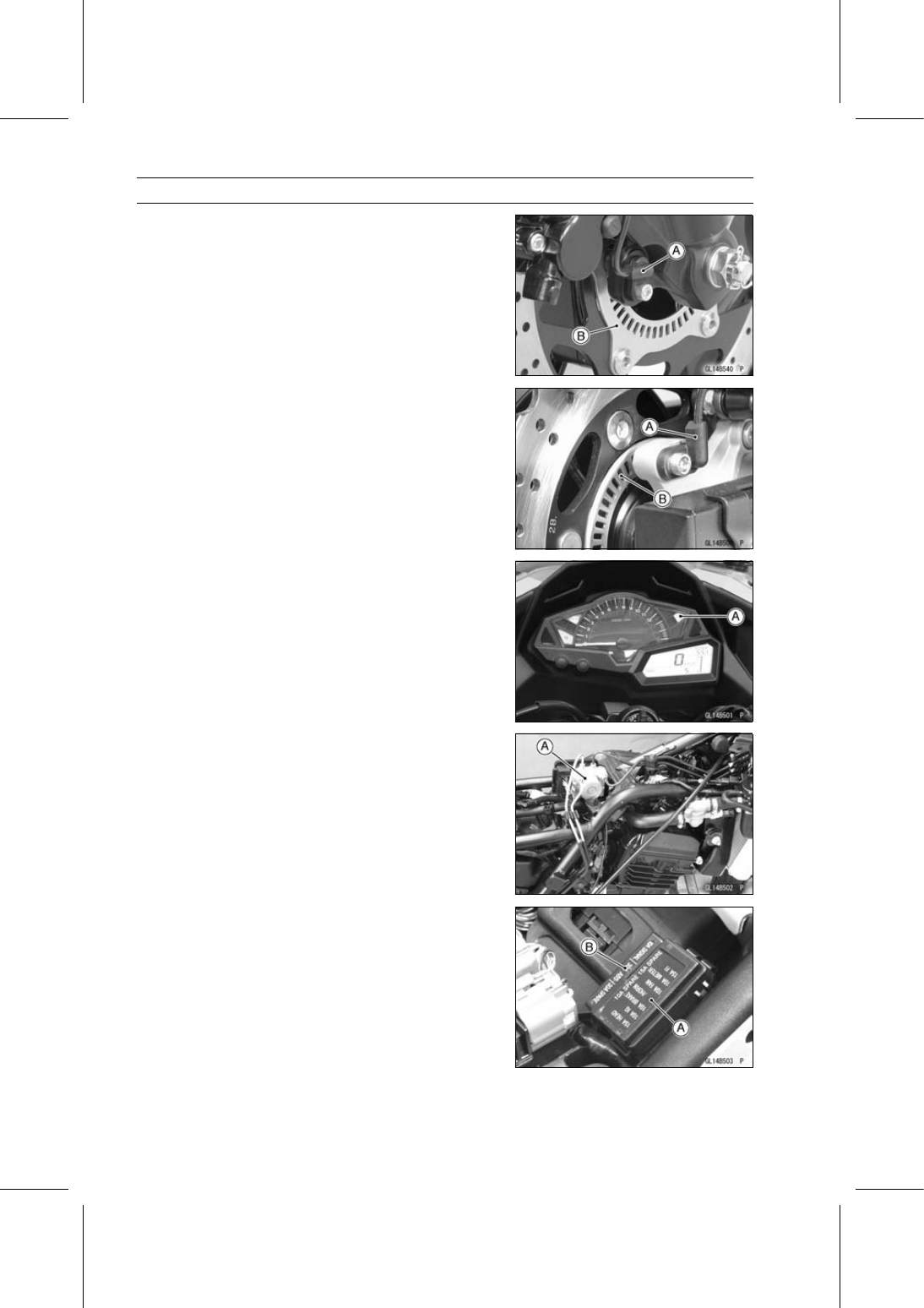
Parts Location

Front Wheel Rotation Sensor [A]
Front Wheel Rotation Sensor Rotor [B]

Rear Wheel Rotation Sensor [A]
Rear Wheel Rotation Sensor Rotor [B]

Yellow ABS Indicator Light (LED) [A]

ABS Hydraulic Unit [A]

Fuse Box 1 [A]
Fuse Box 2 [B]

BRAKES 12-29

Anti-Lock Brake System (Equipped Models)

ABS Kawasaki Diagnostic System Connector [A]
ABS Self-diagnosis Terminal [B]

ABS System Wiring Diagram

1. Front Brake Light Switch
2. Ignition Switch
3. Meter Unit
4. Yellow ABS Indicator Light (LED)
5. Front Wheel Rotation Sensor
6. Water-proof Joint 7
7. Fuse Box 1
8. Meter Fuse 10 A
9. Brake/Horn Fuse 10 A

10. Ignition Fuse 10 A

11. ABS Fuse 30 A

12. Fuse Box 2
13. ABS Hydraulic Unit
14. ABS Self-diagnosis Terminal
15. ABS Kawasaki Diagnostic System Connector
16. Main Fuse 30 A
17. Starter Relay
18. Battery 12 V 8 Ah
19. Engine Ground
20. Frame Ground 4
21. Rear Brake Light Switch
22. Rear Wheel Rotation Sensor

12-30 BRAKES

Anti-Lock Brake System (Equipped Models)

Color Codes:

BK: Black

BL: Blue

BR: Brown

CH: Chocolate

DG: Dark Green

G: Green

GY: Gray

LB: Light Blue

LG: Light Green

O: Orange

P: Pink

PU: Purple

R: Red

V: Violet

W: White

Y: Yellow

ABS Hydraulic Unit Terminal Names

2. Unused
3. Unused
4. Front and Rear Brake Light Switch Signal: BL/R
5. ABS Kawasaki Diagnostic System Terminal: P
6. Power Supply to Rear Wheel Rotation Sensor: W/G
7. Power Supply: BR/W
8. Power Supply to Front Wheel Rotation Sensor: W/BK
9. Ground: BK/Y

11. Unused

12. Unused
13. Yellow ABS Indicator Light (LED): V
14. ABS Self-Diagnosis Terminal: GY
15. Rear Wheel Rotation Sensor Signal Input: BK/O
16. Unused
17. Front Wheel Rotation Sensor Signal Input: BK/W
18. Power Supply to ABS Motor Relay: R/W

BRAKES 12-31

Anti-Lock Brake System (Equipped Models)

ABS Servicing Precautions

There are a number of important precautions that should

be followed servicing the ABS system.

This ABS system is designed to be used with a 12 V
sealed battery as its power source. Do not use any
other battery except for a 12 V sealed battery as a power
source.

Do not reverse the battery cable connections. This will
damage the ABS hydraulic unit.

To prevent damage to the ABS parts, do not disconnect
the battery cables or any other electrical connections
when the ignition switch is on or while the engine is
running.

Take care not to short the leads that are directly con-
nected to the battery positive (+) terminal to the chassis
ground.

Do not turn the ignition switch on while any of the ABS
electrical connectors are disconnected. The ABS hy-
draulic unit memorizes service codes.

Do not spray water on the electrical parts, ABS parts, con-
nectors, leads and wiring.

If a transceiver is installed on the motorcycle, make sure
that the operation of the ABS system is not influenced
by electric wave radiated from the antenna. Locate the
antenna as far as possible away from the ABS hydraulic
unit.

Whenever the ABS electrical connections are to be dis-
connected, first turn the ignition switch off.

The ABS parts should never be struck sharply, as with
a hammer, or allowed to fall on a hard surface. Such a
shock to the parts can damage them.

The ABS parts cannot be disassembled. Even if a fault is
found, do not try to disassemble and repair the ABS parts,
replace it.

The ABS has many brake lines, pipes, and leads. And
the ABS cannot detect problems with the conventional
braking system (brake disc wear, unevenly worn brake
pad, and other mechanical faults). To prevent trouble,
check the brake lines and pipes for correct routing and
connection, the wiring for correct routing, and the brakes
for proper braking power. Be sure to check for fluid leak-
age, and bleed the brake line thoroughly.

12-32 BRAKES

Anti-Lock Brake System (Equipped Models)

WARNING

Air in the brake lines diminish braking performance
and can cause an accident resulting in injury or
death. If any of the brake line fittings, including the
ABS hydraulic unit joint nuts, or the bleed valve is
opened at any time, the air must be bled completely
from the brake line. If the brake lever has a soft
or "spongy" feeling mushy when it is applied, there
might be air in the brake lines or the brake may be
defective. Do not operate the vehicle and service
the brake system immediately.

NOTICE

Do not ride the motorcycle with air in the brake line,
or the ABS could malfunction.

The yellow ABS indicator light (LED) [A] may light if the
tire pressure is incorrect, a non-recommended tire is in-
stalled, or the wheel is deformed. If the indicator light
lights, remedy the problem and clear the service code.

WARNING

Use of non-recommended tires may cause malfunc-
tioning of ABS and can lead to extended braking
distance resulting in an accident causing serious
injury or death. Always use recommended stan-
dard tires for this motorcycle.

BRAKES 12-33

Anti-Lock Brake System (Equipped Models)

The yellow ABS indicator light (LED) may come on if the
engine is run with the motorcycle on its stand and the
transmission in gear. If the indicator light comes on, just
turn the ignition switch off, then clear service code 42,
which indicates a “Faulty front wheel rotation sensor”.

When the ABS operates, the ABS makes noise and the
rider feels the reaction force on the brake lever and brake
pedal. This is a normal condition. It informs the rider that
the ABS is operating normally.

Service codes detected once by the ABS hydraulic unit
will be memorized in the ABS hydraulic unit. Therefore,
after maintenance work is finished, be sure to erase the
service codes. Do not erase the service codes during
troubleshooting. Wait until all the checks and repair work
are finished to prevent duplication of previous service
codes and unnecessary maintenance work.

Before delivering the motorcycle to the customer, be
sure to erase any service codes which might be stored in
the ABS hydraulic unit. Using the self-diagnosis feature,
make sure that the yellow ABS indicator light (LED) lights.
A fully charged battery is a must for conducting reliable
self-diagnosis. Test run the motorcycle at a speed of
more than 30 km/h (19 mph) to see that the yellow ABS
indicator light (LED) does not come on. Finally, test run
the motorcycle at a speed of more than 30 km/h (19 mph)
and brake suddenly to see that the motorcycle stops
without loss of steering control and the ABS operates
normally (the reaction force generated is felt in the brake
lever and pedal). This completes the final inspection.

ABS Troubleshooting Outline

When an abnormality in the system occurs, the yellow

ABS indicator light (LED) lights up to alert the rider. In ad-
dition, the nature of the fault is stored in the memory of the
ABS hydraulic unit and when in the self-diagnosis mode,
the service code [A] is indicated by the number of times the
yellow ABS indicator light (LED) blinks. The service codes
stored in memory are not erased until the mode has been
changed to the fault erase mode after the fault has been
corrected. Therefore, after correcting the problem, always
erase the service codes and then run the self-diagnosis pro-
gram to confirm normal signal output. When, due to a mal-
function, the yellow ABS indicator light (LED) remains lit, get
a thorough understanding of the background before starting
the repair work. Ask the rider about the conditions [B] under
which the problem occurred and try to determine the cause
[C]. Do not rely solely on the ABS self-diagnosis function,
use common sense; check the brakes for proper braking
power, and brake fluid level, search for leaks, etc.

12-34 BRAKES

Anti-Lock Brake System (Equipped Models)

Even when the ABS is operating normally, the yellow ABS

indicator light (LED) may light up under the conditions listed
below. Turn the ignition switch off to stop the indicator light.
If the motorcycle runs without erasing the service code, the
light may light up again.

After continuous riding on a rough road.

When the engine is started with the stand raised and the
transmission engaged, and the rear wheel turns.

When accelerating so abruptly that the front wheel leaves
the ground.

When the ABS has been subjected to strong electrical
interference.

When tire pressure is abnormal. Adjust tire pressure.

When a tire different in size from the standard size is being
used. Replace with standard size.

When the wheel is deformed. Replace the wheel.

Much of the ABS troubleshooting work consists of con-

firming continuity of the wiring. The ABS parts are assem-
bled and adjusted by the manufacturer, so there is no need
to disassemble or repair them. Replace the ABS hydraulic
unit.

The basic troubleshooting procedures are listed below.

Carry out pre-diagnosis inspections as a preliminary in-
spection.

Determine the fault using the self-diagnosis function.

Check wiring and connections from the ABS hydraulic
unit connector to the suspected faulty ABS part, using the
hand tester.

Special Tool - Hand Tester: 57001-1394

Visually inspect the wiring for signs of burning or fraying.
If any wiring is poor, replace the damaged wiring.

Pull each connector [A] apart and inspect it for corrosion,
dirt and damage.
If the connector is corroded or dirty, clean it carefully. If it
is damaged, replace it.

Check the wiring for continuity.

Use the wiring diagram to find the ends of the lead which
is suspected of being a problem.

Connect the hand tester between the ends of the leads.

Special Tool - Hand Tester: 57001-1394

Set the tester to the × 1

range, and read the tester.

If the tester does not read 0

, the lead is defective. Re-

place the main harness [B] if necessary.

Narrow down suspicious parts and close in on the faulty
ABS part by repeating the continuity tests.
If no abnormality is found in the wiring or connectors, the
ABS parts are the next likely suspects. Check each part
one by one.
If an abnormality is found, replace the affected ABS part.

BRAKES 12-35

Anti-Lock Brake System (Equipped Models)

ABS Diagnosis Flow Chart

12-36 BRAKES

Anti-Lock Brake System (Equipped Models)

Inquiries to Rider

Each rider reacts to problems in different ways, so it is important to confirm what kind of condition
the rider is dissatisfied with.

Try to find out exactly what problem occurs under exactly what conditions by asking the rider; know-
ing this information may help you reproduce the problem in the shop.

The diagnosis sheet will help prevent you from overlooking any keys, so always use it.

Sample Diagnosis Sheet

Rider name:

Registration No. (license plate No.):

Year of initial registration:

Model:

Engine No.:

Frame No.:

Date problem occurred:

Frequency:

Weather:

Mileage:

Phenomenon

Brake lever vibration or noise

Pedal vibration or noise

Yellow ABS indicator light (LED) blinks

Yellow ABS indicator light (LED) remains lit up

Braking distance too long

Abnormal brake lever movement

Abnormal pedal movement

ABS not working

ABS works but yellow ABS indicator light (LED) doesn’t light up

ABS operating too frequently

Engine conditions at
problem

At start-up

After starting

At 5 000 r/min (rpm) or more

Road conditions

Slippery road

(

snow,

gravel,

other )

Rough surface

Other

Driving conditions

High-speed cornering

Driving 30 km/h (19 mph) or above

Driving below 30 km/h (19 mph)

When stopping

When turning

Brake application

Gradual

Abrupt

Other conditions

Large brake lever stroke

Large pedal stroke

BRAKES 12-37

Anti-Lock Brake System (Equipped Models)

Pre-Diagnosis Inspection 1

12-38 BRAKES

Anti-Lock Brake System (Equipped Models)

Pre-Diagnosis Inspection 2

Self-diagnosis Outline

When the yellow ABS indicator light (LED) has blinked or come on, the ABS hydraulic unit mem-

orizes and stores the service code for the service person to troubleshoot easily. The service code
memory is powered directly by the battery and cannot be canceled by the ignition switch.

The ABS hydraulic unit can memorize up to all service codes. Further service codes are memorized

after erasing the preceding all service codes. If there is no fault, the yellow ABS indicator light (LED)
lights, indicating that “The ABS is normal”.

Self-diagnosis Procedures

Before performing the self-diagnosis procedures, make
sure that the yellow ABS indicator light (LED) [A] stays
on to indicate any electrical problem occurring in the ABS
system.

NOTE

Use a fully charged battery for performing self-diagnosis
procedure properly. A insufficient battery may cause
improperly result.

The self-diagnosis procedures should be done with the
motorcycle is stopped.

BRAKES 12-39

Anti-Lock Brake System (Equipped Models)

The ABS hydraulic unit can be store the service codes
including previous ones.

To read out the current service code, erase the stored
service codes once prior reading the service code (see
Service Code Clearing Procedures).

Test ride the motorcycle with 30 km/h (19 mph) or more in
a safety area to store the service code, which correspond
to the current problems.

Remove the seat (see Seat Removal in the Frame chap-
ter).

Ground the self-diagnosis terminal [A] (Gray) to a frame
ground, using a suitable auxiliary lead. Keep the auxiliary
lead ground during self-diagnosis procedure.

Turn the ignition switch to on and read the service code
(see How to Read Service Code).

To exit the self-diagnosis mode, remove the auxiliary lead
from the self-diagnosis terminal.

NOTE

The grounding auxiliary lead must be removed after the
self-diagnosis procedure.

Service Code Clearing Procedures

Start the service code erase mode with the following pro-
cedure.

The erase mode starts when the ABS self-diagnosis ter-
minal is disconnected from the frame ground after starting
the self-diagnosis mode.

The service code can be erased by grounding (time
for at least one second) and ungrounding the ABS
self-diagnosis terminal three times or more within about
12.5 seconds after starting the erase mode and ground-
ing it.

The yellow ABS indicator light (LED) remains lit during the
erase mode.

After erasing, the yellow ABS indicator light (LED) blinks
two times and lights.

Once erasing is finished, enter the self-diagnosis mode
again to confirm that the service codes have been
erased. If the ABS has been reset and all codes have
been erased, the yellow ABS indicator light (LED) lights.

12-40 BRAKES

Anti-Lock Brake System (Equipped Models)

BRAKES 12-41

Anti-Lock Brake System (Equipped Models)

Self-diagnosis Flow Chart

12-42 BRAKES

Anti-Lock Brake System (Equipped Models)

How to Read Service Codes

Service codes are shown by a series of long and short blinks of the yellow ABS indicator light (LED)
as shown below.

Read 10th digit and unit digit as the yellow ABS indicator light (LED) blinks.

When there are a number of faults, a maximum of all service codes can be stored.

For the display pattern, the display will begin starting from the small number code entered, then the
display is repeated from the smallest number code once again.

If there is no fault, the yellow ABS indicator light (LED) lights as shown in the figure.

How to Erase Service Codes

Even if the ignition switch is turned off, the battery or the ABS hydraulic unit are disconnected, all
service codes remain in the ABS hydraulic unit.

Refer to the Service Code Clearing Procedure for the service code erasure.

BRAKES 12-43

Anti-Lock Brake System (Equipped Models)

Service Code Table

Service

Code

Yellow ABS Indicator

Light (LED)

Problems

Light State

Stays on* (Error function
after the ignition switch
turned on)

Main harness, meter unit, wheel rotation
sensor(s) or ABS unit abnormal

ON

Does not go on (When the
ignition switch turned on)

Main harness, meter unit or ABS unit
abnormal

OFF

13

Rear intake solenoid valve trouble (wiring
shorted or open)

ON

14

Rear outlet solenoid valve trouble (wiring
shorted or open)

ON

17

Front intake solenoid valve trouble (wiring
shorted or open)

ON

18

Front outlet solenoid valve trouble (wiring
shorted or open)

ON

19

ABS solenoid valve relay trouble [stuck
relay (ON or OFF)]

ON

25

Front, rear wheel rotation difference
abnormal (substandard tire)

ON

35

ABS motor trouble (mechanical stuck)

ON

42

Front wheel rotation sensor signal abnormal
(sensor or rotor missing, too large
clearance, rotor tooth worn or missing)

ON

43

Front or rear wheel rotation sensor wiring
(wiring shorted or open, connector bad
connection)

ON

44

Rear wheel rotation sensor signal abnormal
(sensor or rotor missing, too large
clearance, rotor tooth worn or missing)

ON

45

Rear wheel rotation sensor wiring (wiring
shorted or open, connector bad connection)

ON

52

Power supply voltage abnormal
(low-voltage)

ON

53

Power supply voltage abnormal
(high-voltage)

ON

55

ABS Hydraulic Unit Internal Error (ECU
operation abnormal)

ON

*: In spite of the service code is not stored, the yellow ABS Indicator Light (LED) does not go off

when the 2 seconds later from the ignition switch turned on.

12-44 BRAKES

Anti-Lock Brake System (Equipped Models)

Yellow ABS Indicator Light (LED) Inspection

In this model, the yellow ABS indicator light (LED) [A]
goes on or blinks by the control of the ABS hydraulic unit.

Yellow ABS Indicator Light (LED) Stays ON (Error func-
tion after the ignition switch turned on - No Service
Code)

Perform the Pre-Diagnosis Inspection 1.

Check the system connectors for loose or poorly contact.

Step 1

Check the ignition fuse 10 A in the fuse box 1 [A] for blown.
If the fuse is blown, replace the fuse.
If the fuse is not blown, go to next step.

Step 2

Measure the battery terminal voltage using a voltmeter
[A].

The battery voltage should be within 10

16 V.

If the voltage without specifications, recharge or replace
the battery.
If the voltage within specifications, go to next step.

Step 3

Disconnect the ABS hydraulic unit connector.

Check the voltage between the terminal 7 (BR/W) (+) [A]
and terminal 9 (BK/Y) (–) [B] of the ABS hydraulic unit
connector.

Special Tool - Hand Tester: 57001-1394

The battery voltage (10

16 V) should be appeared while

the ignition switch turned on.
If the battery voltage appeared, go to step 4.
If the battery voltage does not appear, go to next step.

Step 3-1

Check the voltage between the terminal 7 (BR/W) (+) [A]
of the ABS hydraulic unit connector and a frame ground
(–) [B].

Special Tool - Hand Tester: 57001-1394

The battery voltage (10

16 V) should be appeared while

the ignition switch turned on.
If the battery voltage does not appear, repair or replace
the main harness.
If the battery voltage appeared, go to next step.

BRAKES 12-45

Anti-Lock Brake System (Equipped Models)

Step 3-2

Check for continuity between the terminal 9 (BK/Y) [A] of
the ABS hydraulic unit connector and a frame ground [B].
If there is no continuity, repair or replace the main har-
ness.
If there is continuity, replace the ABS hydraulic unit.

Step 4

With the self-diagnosis terminal connected to the ground,
check for continuity between the terminal 9 (BK/Y) [A] and
terminal 14 (GY) [B] of the ABS hydraulic unit connector.
If there is no continuity, repair or replace the main har-
ness.
If there is continuity, go to next step.

Step 5

Jump the terminal 9 (BK/Y) [A] and terminal 13 (V) [B] at
the ABS hydraulic unit connector using a jumper read [C].

Check the yellow ABS indicator light (LED) with the igni-
tion switch turned on.
If the indicator goes off, replace the ABS hydraulic unit.
If the indicator goes on, go to next step.

Step 6

Disconnect the connector from the meter unit (see Meter
Unit Removal in the Electrical System chapter).

Check for continuity between the terminal 13 (V) [A] of the
ABS hydraulic unit connector [B] and terminal 9 (V) [C] of
the meter connector [D].
If there is no continuity, repair or replace the main har-
ness.
If there is continuity, replace the meter unit with a new
one.

Yellow ABS Indicator Light (LED) does not go on (When
the Ignition Switch turned on)

Perform the Pre-Diagnosis Inspection 1.

Check the system connectors for loose or poorly contact.

Step 1

Check the meter fuse 10 A in the fuse box 1 for blown.
If the fuse is blown, replace the fuse.
If the fuse is not blown, go to next step.

12-46 BRAKES

Anti-Lock Brake System (Equipped Models)

Step 2

Disconnect the ABS hydraulic unit connector [A] and
check the yellow ABS indicator light (LED) for function.

The yellow ABS indicator light (LED) should goes on when
the ignition switch turned on.
If the indicator does not goes on, go to next step.
If the indicator goes on, go to step 3.

Step 2-1

Disconnect the connector from the meter unit (see Meter
Unit Removal in the Electrical System chapter).

Check for continuity between the terminal 13 (V) [A] of the
ABS hydraulic unit connector and a frame ground [B].
If there is continuity, repair or replace the main harness.
If there is no continuity, replace the meter unit with a new
one.

Step 3

Check the voltage between the terminal 9 (BK/Y) (–) [A]
and terminal 7 (BR/W) (+) [B] of the ABS hydraulic unit
connector.

Special Tool - Hand Tester: 57001-1394

The battery voltage (10

16 V) should not appear while

the ignition switch turned off.
If the battery voltage appeared, repair or replace the main
harness.
If the battery voltage does not appear, go to next step.

Step 4

Check the voltage between the terminal 9 (BK/Y) (–) [A]
and terminal 8 (W/BK) (+) [B] of the ABS hydraulic unit
connector.

Special Tool - Hand Tester: 57001-1394

The battery voltage (10

16 V) should not appear while

the ignition switch turned off.
If the battery voltage appeared, repair or replace the main
harness.
If the battery voltage does not appear, go to next step.

Step 5

Check the voltage between the terminal 9 (BK/Y) (–) [A]
and terminal 6 (W/G) (+) [B] of the ABS hydraulic unit
connector.

Special Tool - Hand Tester: 57001-1394

The battery voltage (10

16 V) should not appear while

the ignition switch turned off.
If the battery voltage appeared, repair or replace the main
harness.
If the battery voltage does not appear, replace the ABS
hydraulic unit.

BRAKES 12-47

Anti-Lock Brake System (Equipped Models)

ABS Unit Solenoid Valve Inspection (Service Code

13, 14, 17, 18)

These codes indicate there is a problem in the solenoid
valves, which integrated into the ABS Hydraulic Unit.
Therefore the solenoid valves cannot be checked directly.

Check the system connectors for loose or poorly contact.

In order to confirm a existing problem in the system, erase
the service code and then perform the pre-diagnosis in-
spection 1 and 2.
If same service code is indicated again, faulty solenoid
valve in the ABS hydraulic unit. Replace the ABS hy-
draulic unit.
If the service code does not indicate, ABS system is nor-
mal (service code is not stored; temporary failure).

ABS Solenoid Valve Relay Inspection (Service

Code 19)

Perform the Pre-Diagnosis Inspection 1 and 2.

Check the system connectors for loose or poorly contact.

Step 1

Check the ABS fuse 30 A [A] in the fuse box 2 for blown.
If the ABS fuse is blown, replace the fuse.
If the fuse is not blown, go to next step.

Step 2

Disconnect the ABS hydraulic unit connector.

Check the voltage between the terminal 9 (BK/Y) (–) [A]
and terminal 18 (R/W) (+) [B] of the ABS hydraulic unit
connector.

Special Tool - Hand Tester: 57001-1394

The battery voltage (10

16 V) should appear while the

ignition switch turned on.
If the battery voltage does not appear, repair or replace
the main harness.
If the battery voltage appeared, replace the ABS hydraulic
unit.

Front, Rear Wheel Rotation Difference Abnormal

Inspection (Service Code 25)

Perform the Pre-Diagnosis Inspection 1 and 2.

Step 1

Check the front and rear tire/wheel conditions for tire pres-
sure, tire size/types, abnormal wear and deformations
(see Wheels/Tires in the Periodic Maintenance chapter).
If the tire and/or wheel are in bad condition, correct them
to the normal condition.
If there is no problem, go to next step.

Step 2

Visually inspect the sensor rotor [A] for missing teeth or
clogging with foreign matter (see Wheel Rotation Sensor
Rotor Inspection).
Clean or correct the parts if necessary.
If the all parts correct, go to next step.

12-48 BRAKES

Anti-Lock Brake System (Equipped Models)

Step 3

Measure the front and rear wheel rotation sensor air gaps
(see Wheel Rotation Sensor Air Gap Inspection).
If the air gap is not within the specification, recheck the
hub bearing, sensor, sensor rotor and sensor installation
condition.
If the air gap is within the specification, replace the ABS
hydraulic unit.

ABS Motor Inspection (Service Code 35)

Perform the Pre-Diagnosis Inspection 1 and 2.

Check the system connectors for loose or poorly contact.

In order to confirm a existing problem in the system, erase
the service code and then recheck the yellow ABS indi-
cator light (LED).
If same service code is indicated again, faulty ABS Motor
in the ABS hydraulic unit. Replace the ABS hydraulic unit.
If the service code does not indicate, ABS system is nor-
mal (service code is not stored; temporary failure).

Wheel Rotation Sensor Signal Abnormal

Inspection (Front: Service Code 42) (Rear:

Service Code 44)

Perform the Pre-Diagnosis Inspection 1 and 2.

Check the system connectors for loose or poorly contact.

Step 1

Measure the front or rear wheel rotation sensor air gap
(see Wheel Rotation Sensor Air Gap Inspection).
If the air gap is not within the specification, recheck the
hub bearing, sensor, sensor rotor and sensor installation
condition.
If the air gap is within the specification, go to next step.

Step 2

Check that there is iron or other magnetic deposits be-
tween the front or rear wheel rotation sensor [A] and sen-
sor rotor, and the sensor rotor slots [B] for obstructions.

Check the installation condition of the sensor for loose-
ness.

Check the sensor tip and sensor rotor slots for deforma-
tion or damage (e.g. chipped sensor rotor teeth).
If the sensor and sensor rotor in bad condition, clean or
replace the faulty parts.
If all items are correct, go to next step.

BRAKES 12-49

Anti-Lock Brake System (Equipped Models)

Step 3

Check the front and rear tire/wheel conditions for tire pres-
sure, tire size/types, abnormal wear and deformations
(see Wheels/Tires in the Periodic Maintenance chapter).
If the tire and/or wheel are in bad condition, correct them
if necessary and recheck.
If all items are good condition, replace the ABS unit.

Front or Rear Wheel Rotation Sensor Wiring

Inspection (Service Code 43)

This code is indicates there is a trouble in the front or rear
wheel rotation sensor.

Perform the Pre-Diagnosis Inspection 1 and 2.

Check the system connectors for loose or poorly contact.

Step 1

Disconnect the ABS hydraulic unit connector.

Check for continuity between the terminal 9 (BK/Y) [A] and
terminal 8 (W/BK) [B] of the ABS hydraulic unit connector.
If there is continuity, go to next step.
If there is no continuity, go to step 2.

Step 1-1

Disconnect the front wheel rotation sensor connector [A].

Recheck the continuity between the terminal 9 (BK/Y) and
terminal 8 (W/BK) of the ABS hydraulic unit connector.
If there is continuity, repair or replace the main harness.
If there is no continuity, replace the front wheel rotation
sensor.

Step 2

Check for continuity between the terminal 9 (BK/Y) [A] and
terminal 6 (W/G) [B] of the ABS hydraulic unit connector.
If there is continuity, go to next step.
If there is no continuity, go to step 3.

12-50 BRAKES

Anti-Lock Brake System (Equipped Models)

Step 2-1

Disconnect the rear wheel rotation sensor connector.

Recheck the continuity between the terminal 9 (BK/Y) [A]
and terminal 6 (W/G) [B] of the ABS hydraulic unit con-
nector.
If there is continuity, repair or replace the main harness.
If there is no continuity, replace the rear wheel rotation
sensor.

Step 3

Connect the front wheel rotation sensor connector.

Check for continuity between the terminal 9 (BK/Y) [A] and
terminal 17 (BK/W) [B] of the ABS hydraulic unit connec-
tor.
If there is continuity, go to next step.
If there is no continuity, go to step 4.

Step 3-1

Disconnect the front wheel rotation sensor connector.

Recheck the continuity between the terminal 9 (BK/Y) [A]
and terminal 17 (BK/W) [B] of the ABS hydraulic unit con-
nector.
If there is continuity, repair or replace the main harness.
If there is no continuity, replace the front wheel rotation
sensor.

Step 4

Disconnect the front wheel rotation sensor connector [A].

Check for continuity between the terminal 8 (W/BK) [B]
of the ABS hydraulic unit connector [C] and terminal 2
(W/BK) [D] of the front wheel rotation sensor connector
(main harness side).
If there is no continuity, repair or replace the main har-
ness.
If there is continuity, go to next step.

Step 5

With disconnecting the front wheel rotation sensor con-
nector [A], check for continuity between the terminal 17
(BK/W) [B] of the ABS hydraulic unit connector [C] and
the 1 (BK/W) terminal [D] of the front wheel rotation sen-
sor connector (main harness side).
If there is no continuity, repair or replace the main har-
ness.
If there is continuity, go to next step.

BRAKES 12-51

Anti-Lock Brake System (Equipped Models)

Step 6

Connect the front wheel rotation sensor connector.

Connect the 4.5

5.0 V DC power (e.g. three AA dry

battery in series [A]) between the terminal 17 (BK/W) (–)
[B] and terminal 8 (W/BK) (+) [C] of the ABS hydraulic unit
connector to measure DC amperage.

Special Tool - Hand Tester: 57001-1394

Be careful not to reverse connection of the DC power po-
larity.

The measured DC amperage should be within 3

17 mA.

If measurement is abnormal, replace the front wheel ro-
tation sensor.
If measurement is normal, replace the ABS hydraulic unit.

Rear Wheel Rotation Sensor Wiring Inspection

(Service Code 45)

This code is indicates there is a trouble in the rear wheel
rotation sensor. However the front and rear wheel rota-
tion sensor inspection should be performed if this code is
indicated.

Perform the Pre-Diagnosis Inspection 1 and 2.

Check the system connectors for loose or poorly contact.

Step 1

Disconnect the ABS hydraulic unit connector.

Check for continuity between the terminal 9 (BK/Y) [A] and
terminal 8 (W/BK) [B] of the ABS hydraulic unit connector.
If there is continuity, go to next step.
If there is no continuity, go to step 2.

Step 1-1

Disconnect the front wheel rotation sensor connector [A].

Recheck the continuity between the terminal 9 (BK/Y) and
terminal 8 (W/BK) of the ABS hydraulic unit connector.
If there is continuity, repair or replace the main harness.
If there is no continuity, replace the front wheel rotation
sensor.

12-52 BRAKES

Anti-Lock Brake System (Equipped Models)

Step 2

Check for continuity between the terminal 9 (BK/Y) [A] and
terminal 6 (W/G) [B] of the ABS hydraulic unit connector.
If there is continuity, go to next step.
If there is no continuity, go to step 3.

Step 2-1

Disconnect the rear wheel rotation sensor connector.

Recheck the continuity between the terminal 9 (BK/Y) [A]
and terminal 6 (W/G) [B] of the ABS hydraulic unit con-
nector.
If there is continuity, repair or replace the main harness.
If there is no continuity, replace the rear wheel rotation
sensor.

Step 3

Connect the rear wheel rotation sensor connector.

Check for continuity between the terminal 9 (BK/Y) [A] and
terminal 15 (BK/O) [B] of the ABS hydraulic unit connec-
tor.
If there is continuity, go to next step.
If there is no continuity, go to step 4.

Step 3-1

Disconnect the rear wheel rotation sensor connector [A].

Recheck the continuity between the terminal 9 (BK/Y) and
terminal 15 (BK/O) of the ABS hydraulic unit connector.
If there is continuity, repair or replace the main harness.
If there is no continuity, replace the rear wheel rotation
sensor.

Step 4

Disconnect the rear wheel rotation sensor connector [A].

Check for continuity between the terminal 6 (W/G) [B] of
the ABS hydraulic unit connector [C] and terminal 2 (W/G)
[D] of the rear wheel rotation sensor connector (main har-
ness side).
If there is no continuity, repair or replace the main har-
ness.
If there is continuity, go to next step.

BRAKES 12-53

Anti-Lock Brake System (Equipped Models)

Step 5

With disconnecting the rear wheel rotation sensor con-
nector [A], check for continuity between the terminal 15
(BK/O) [B] of the ABS hydraulic unit connector [C] and
terminal 1 (BK/O) [D] of the rear wheel rotation sensor
connector (main harness side).
If there is no continuity, repair or replace the main har-
ness.
If there is continuity, go to next step.

Step 6

Connect the rear wheel rotation sensor connector.

Connect the 4.5

5.0 V DC power (e.g. three AA dry

battery in series [A]) between the terminal 15 (BK/O) (–)
[B] and terminal 6 (W/G) (+) [C] of the ABS hydraulic unit
connector to measure DC amperage.

Special Tool - Hand Tester: 57001-1394

Be careful not to reverse connection of the DC power po-
larity.

The measured DC amperage should be within 3

17 mA.

If measurement is abnormal, replace the rear wheel rota-
tion sensor.
If measurement is normal, replace the ABS hydraulic unit.

Power Supply Voltage Abnormal Inspection

(Service Code 52: Low Voltage) (Service Code 53:

High Voltage)

Step 1

Measure the battery terminal voltage using a voltmeter
[A].

The battery voltage should be within 10

16 V.

If the voltage is not within the specifications, recharge or
replace the battery.
If the voltage within the specifications, go to next step.

Step 2

Check the ABS fuse 30A [A] in the fuse box 2 for blown.
If the ABS fuse is blown, replace the fuse.
If the fuse is not blown, go to next step.

12-54 BRAKES

Anti-Lock Brake System (Equipped Models)

Step 3

Disconnect the ABS hydraulic unit connector.

Check the voltage between the terminal 9 (BK/Y) (–) [A]
and terminal 18 (R/W) (+) [B] of the ABS hydraulic unit
connector.

Special Tool - Hand Tester: 57001-1394

The battery voltage (10

16 V) should appear while the

ignition switch turned on.
If the battery voltage does not appear, repair or replace
the main harness.
If the battery voltage appeared, go to next step.

Step 4

Check the voltage between the terminal 9 (BK/Y) (–) [A]
and terminal 7 (BR/W) (+) [B] of the ABS hydraulic unit
connector.

Special Tool - Hand Tester: 57001-1394

The battery voltage (10

16 V) should appear while the

ignition switch turned on.
If the battery voltage not appeared, repair or replace the
main harness.
If the battery voltage does appear, replace the ABS hy-
draulic unit.

ABS Hydraulic Unit Internal Error Inspection

(Service Code 55)

This service code indicates there is an internal error for
the ECU integrated with the ABS hydraulic unit regarding
the wheel speed detection.

Perform the Pre-Diagnosis Inspection 1 and 2.

Check the system connectors for loose or poorly contact.

Step 1

Measure the front and rear wheel rotation sensor air gaps
(see Wheel Rotation Sensor Air Gap Inspection).
If the air gap is not within the specification, correct the air
gap accordingly.
If the air gap is within the specification, go to next step.

Step 2

Check that there is iron or other magnetic deposits be-
tween the both wheel rotation sensor [A] and sensor ro-
tor, and the sensor rotor slots [B] for obstructions.

Check the installation condition of the sensor for loose-
ness.

Check the sensor tip and sensor rotor slots for deforma-
tion or damage (e.g. chipped sensor rotor teeth).
If the sensor and sensor rotor in bad condition, clean or
replace the faulty parts.
If all items are correct, go to next step.

Step 3

Check the front and rear tire/wheel conditions for tire pres-
sure, tire size/types, abnormal wear and deformations
(see Wheels/Tires in the Periodic Maintenance chapter).
If the tire and/or wheel are in bad condition, correct them
to the normal condition.
If there is no problem, replace the ABS hydraulic unit.

BRAKES 12-55

Anti-Lock Brake System (Equipped Models)

ABS Hydraulic Unit Removal

NOTICE

The ABS hydraulic unit [A] has been adjusted
and set with precision at the factory. Therefore, it
should be handled carefully, never struck sharply,
as with a hammer, or allowed to fall on a hard
surface.
Be careful not to get water or mud on the ABS hy-
draulic unit.

Drain the brake fluid from the front and rear brake lines.

Drain the brake fluid through the bleed valve by pumping
the brake lever and pedal.

Be sure to place a cloth under the ABS hydraulic unit.

Remove:

Fuel Tank (see Fuel Tank Removal in the Fuel System
(DFI) chapter)
Right Middle Fairing (see Middle Fairing Removal in the
Frame chapter)

Turn the ignition switch off.

Remove the clamp bolts [A] to free the brake pipes [B]
from the clamps [C].

Pull the lever [A] to disconnect the ABS hydraulic unit con-
nector [B].

NOTICE

To protect the ABS hydraulic unit from the electri-
cal surge, always disconnect the ABS hydraulic unit
connector while the ignition switch is turned off.

Loosen the ABS hydraulic unit mounting bolts [C] before
disconnecting the brake pipes.

Loosen the brake pipe joint nuts [D] fully using the flare
nut wrench.

Remove the ABS hydraulic unit [E] from the frame.

NOTE

Be careful not to bend the brake pipe while removing
the ABS hydraulic unit.

Plug the port [A] on the ABS hydraulic unit [B] to prevent
entering a foreign matter into the unit.

Wrap the brake pipe openings with a vinyl bag to prevent
brake fluid leakage and entering a foreign matter into the
hydraulic system.

NOTICE

Do not allow entering a foreign matter into the hy-
draulic system while disconnecting the hydraulic
lines.

Brake fluid quickly ruins painted plastic surfaces;
any spilled fluid should be completely washed
away immediately.

12-56 BRAKES

Anti-Lock Brake System (Equipped Models)

Remove:

Bolts [A] and Washers
Bracket [B]

NOTICE

The ABS hydraulic unit has been adjusted and set
with precision at the factory. Do not try to disas-
semble and repair the ABS hydraulic unit.

ABS Hydraulic Unit Installation

Install the bracket to the ABS hydraulic unit [A] if removed.

Position the ABS hydraulic unit on the frame.

Install the brake pipes to the ABS hydraulic unit and screw
the flare nut loosely.

To Front Calipers [B]
To Front Master Cylinder [C]
To Rear Caliper [D]
To Rear Master Cylinder [E]
Front [F]

Install the ABS hydraulic unit mounting bolts [A].

Tighten the brake pipe joint nuts [B] with the flare nut
wrench.

Torque - Brake Pipe Joint Nuts: 18 N·m (1.8 kgf·m, 13 ft·lb)

Push the lever [C] to connect the ABS hydraulic unit con-
nector [D].

Install the removed parts (see appropriate chapters).

Fill the ABS hydraulic system with recommend brake fluid
(see Brake Fluid Change in the Periodic Maintenance
chapter).

ABS Hydraulic Unit Inspection

Remove the ABS hydraulic unit (see ABS Hydraulic Unit
Removal).

Visually inspect the ABS hydraulic unit.
Replace the ABS hydraulic unit if any of them are cracked,
or otherwise damaged.

Visually inspect the connector terminals [A].
Replace the ABS hydraulic unit or main harness if either
of the terminals are cracked, bent, or otherwise damaged.
If the ABS hydraulic unit connector is clogged with mud
or dust, blow it off with compressed air.

BRAKES 12-57

Anti-Lock Brake System (Equipped Models)

Front Wheel Rotation Sensor Removal

NOTICE

The wheel rotation sensor should be handled care-
fully, never struck sharply, as with a hammer, or al-
lowed to fall on a hard surface since the wheel rota-
tion sensor is precision made. Be careful not to get
water or mud on the wheel rotation sensor.
Do not try to disassemble or repair the wheel rota-
tion sensor.

Remove:

Fuel Tank (see Fuel Tank Removal in the Fuel System
(DFI) chapter)

Disconnect the front wheel rotation sensor connector [A]
and clear the sensor lead from the clamp [B].

Clear the sensor lead from the clamp [A].

Remove:

Clamps [A]
Bolt [B]
Front Wheel Rotation Sensor [C]

Front Wheel Rotation Sensor Installation

Installation is the reverse of removal.

Run the lead correctly (see Cable, Wire, and Hose Rout-
ing section in the Appendix chapter).

Apply a non-permanent locking agent to the threads of
the wheel rotation sensor bolt.

Tighten:

Torque - Front Wheel Rotation Sensor Bolt: 9.8 N·m (1.0

kgf·m, 87 in·lb)

12-58 BRAKES

Anti-Lock Brake System (Equipped Models)

Rear Wheel Rotation Sensor Removal

NOTICE

The wheel rotation sensor should be handled care-
fully, never struck sharply, as with a hammer, or al-
lowed to fall on a hard surface since the wheel rota-
tion sensor is precision made. Be careful not to get
water or mud on the wheel rotation sensor.
Do not try to disassemble or repair the wheel rota-
tion sensor.

Remove:

Front Seat (see Front Seat Removal in the Frame chap-
ter)

Disconnect the rear wheel rotation sensor connector [A]
and clear the sensor lead [B] from the clamps [C].

Clear the sensor lead [A] from the clamps [B].

Remove:

Grommet [C]
Bolt [D]
Rear Wheel Rotation Sensor [E]

Rear Wheel Rotation Sensor Installation

Installation is the reverse of removal.

Run the lead correctly (see Cable, Wire, and Hose Rout-
ing section in the Appendix chapter).

Apply a non-permanent locking agent to the threads of
the wheel rotation sensor bolt.

Tighten:

Torque - Rear Wheel Rotation Sensor Bolt: 9.8 N·m (1.0

kgf·m, 87 in·lb)

BRAKES 12-59

Anti-Lock Brake System (Equipped Models)

Wheel Rotation Sensor Inspection

Remove the front wheel rotation sensor [A] from the front
fork.

Remove the rear wheel rotation sensor [B] from the
caliper bracket.

Visually inspect the wheel rotation sensors.
Replace the wheel rotation sensor if it is cracked, bent, or
otherwise damaged.
If electrical failure is suspected on the sensors, perform
the electrical check (see Service Code 43 Step 6 for front
sensor or Service Code 45 Step 6 for rear sensor).

Wheel Rotation Sensor Air Gap Inspection

Raise the front/rear wheel off the ground (see Front/Rear
Wheel Removal in the Wheels/Tires chapter).

Measure the air gap between the sensor and sensor rotor
at several points.

Thickness Gauge [A]

Air Gap

Standard:

Front

0.1

1.5 mm (0.004

0.060 in.)

Rear

0.1

1.5 mm (0.004

0.060 in.)

NOTE

The sensor air gap cannot be adjusted.

If the air gap is not within the specification, inspect the hub
bearing (see Hub Bearing Inspection in the Wheels/Tires
chapter), sensor, sensor rotor and sensor installation con-
dition (see Wheel Rotation Sensor Inspection).

Wheel Rotation Sensor Rotor Inspection

Visually inspect the wheel rotation sensor rotor.
If the rotor is deformed or damaged (chipped teeth [A]),
replace the sensor rotor with a new one.
If there is iron or other magnetic deposits [B], remove the
deposits.


Content      ..     11      12      13      14     ..