Kawasaki Ninja 300 / Ninja 300 ABS Motorcycle. Service Manual (2013) - page 11
 

  Index      Manuals     Kawasaki Ninja 300 / Ninja 300 ABS Motorcycle. Service Manual (2013)


Search            copyright infringement  


Content      ..     9      10      11      12     ..


Kawasaki Ninja 300 / Ninja 300 ABS Motorcycle. Service Manual (2013) - page 11


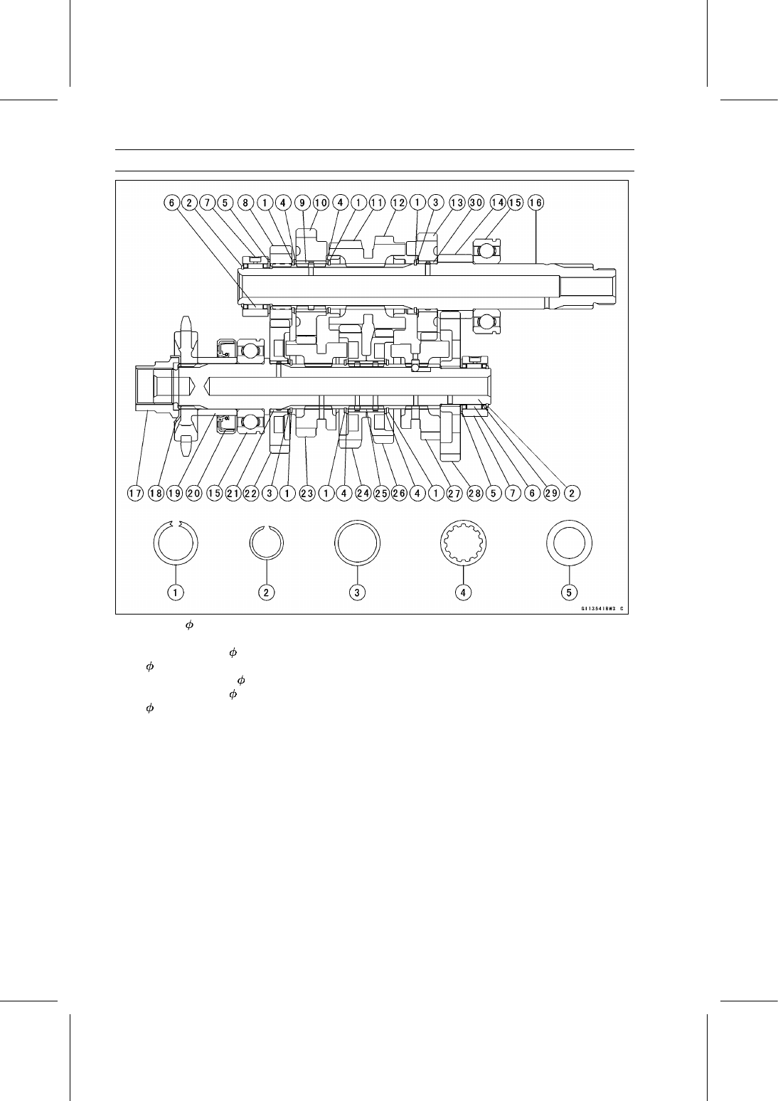
9-32 CRANKSHAFT/TRANSMISSION

Transmission

1. Circlip, 29 mm (1.14 in.)
2. Circlip
3. Thrust Washer, 30 mm (1.18 in.) (Inside Diameter:

25.3 mm (0.996 in.))

4. Toothed Washer, 30 mm (1.18 in.)
5. Thrust Washer, 30 mm (1.18 in.) (Inside Diameter:

20.5 mm (0.807 in.))

6. Needle Bearing
7. Bearing Outer Race
8. 2nd Gear
9. Bushing

10. 6th (Top) Gear

11. 3rd Gear

12. 4th Gear
13. 5th Gear
14. 1st Gear

15. Ball Bearing
16. Drive Shaft
17. Nut
18. Washer
19. Collar
20. Oil Seal
21. Bushing
22. 2nd Gear
23. 6th (Top) Gear
24. 3rd Gear
25. Bushing
26. 4th Gear
27. 5th Gear
28. 1st Gear
29. Output Shaft
30. Bushing

CRANKSHAFT/TRANSMISSION 9-33

Transmission

Shift Drum and Fork Removal

Remove:

Lower Crankcase Half (see Crankcase Splitting)
Transmission Shafts (see Transmission Shaft Removal)

Remove:

Gear Positioning Lever Bolt [A]
Spacer [B]
Gear Positioning Lever [C]
Washer [D]
Spring [E]
Shift Drum Bearing Holder Screws [F]
Shift Drum Bearing Holder [G]
Shift Rods [H]
Shift Forks

Remove the shift drum from the upper crankcase.

Shift Drum and Fork Installation

Apply engine oil to the shift drum, forks and rods.

Insert the shift drum into the upper crankcase half.

Install the shift rods [A], noting the groove position.

Position the one with shorter ears [B] on the drive shaft
and place the pin in the center groove in the shift drum
[C].

The two forks [D] on the output shaft are identical.

Install:

Spring [A]
Washer [B]
Gear Positioning Lever [C]
Spacer [D]

Apply a non-permanent locking agent to the threads of
the gear positioning lever bolt [E], and tighten them.

Torque - Gear Positioning Lever Bolt: 12 N·m (1.2 kgf·m,

106 in·lb)

Check the gear positioning lever and spring for smooth
operation.

9-34 CRANKSHAFT/TRANSMISSION

Transmission

Install the shift drum bearing holder [A].

Apply a non-permanent locking agent to the threads of the
shift drum bearing holder screws [B], and tighten them.

Torque - Shift Drum Bearing Holder Screws: 4.4 N·m (0.45

kgf·m, 39 in·lb)

Shift Drum Disassembly

Remove the shift drum (see Shift Drum and Fork Re-
moval).

While holding the shift drum with a vise, remove the shift
drum cam bolt [A].

Remove:

Shift Drum Cam Holder [B]
Shift Drum Cam [C]
Shift Drum Bearing [D]
Dowel Pin [E]
Shift Drum [F]

Shift Drum Assembly

Be sure to install the dowel pin [A].

Install:

Shift Drum Bearing [B]
Shift Drum Cam [C]
Shift Drum Cam Holder [D]

Apply a non-permanent locking agent to the threads of
the shift drum cam bolt [E], and tighten it.

Torque - Shift Drum Cam Bolt: 9.0 N·m (0.92 kgf·m, 80 in·lb)

Shift Fork Bending Inspection

Visually inspect the shift forks, and replace any fork that is
bent. A bent fork could cause difficulty in shifting, or allow
the transmission to jump out of gear when under power.

90° [A]

CRANKSHAFT/TRANSMISSION 9-35

Transmission

Shift Fork/Gear Groove Wear Inspection

Measure the thickness of the shift fork ears [A], and mea-
sure the width of the gear grooves [B].
If the thickness of a shift fork ear is less than the service
limit, the shift fork must be replaced.

Shift Fork Ear Thickness

Standard:

4.9

5.0 mm (0.193

0.197 in.)

Service Limit: 4.8 mm (0.189 in.)

If the gear groove is worn over the service limit, the gear
must be replaced.

Gear Groove Width

Standard:

5.05

5.15 mm (0.199

0.203 in.)

Service Limit: 5.3 mm (0.209 in.)

Shift Fork Guide Pin/Drum Groove Wear

Inspection

Measure the diameter of each shift fork guide pin [A], and
measure the width of each shift drum groove [B].
If the guide pin on any shift fork is less than the service
limit, the fork must be replaced.

Shift Fork Guide Pin Diameter

Standard:

5.9

6.0 mm (0.232

0.236 in.)

Service Limit: 5.8 mm (0.228 in.)

If any shift drum groove is worn over the service limit, the
drum must be replaced.

Shift Drum Groove Width

Standard:

6.05

6.20 mm (0.238

0.244 in.)

Service Limit: 6.3 mm (0.248 in.)

Gear Dog and Gear Dog Hole Damage Inspection

Visually inspect the gear dogs [A] and gear dog holes [B].
Replace any damaged gears or gears with excessively
worn dogs or dog holes.

WHEELS/TIRES 10-1

10

Wheels/Tires

Table of Contents

Exploded View........................................................................................................................

10-2

Specifications .........................................................................................................................

10-4

Special Tools .........................................................................................................................

10-5

Wheels (Rims) ........................................................................................................................

10-6

Front Wheel Removal .......................................................................................................

10-6

Front Wheel Installation ....................................................................................................

10-6

Rear Wheel Removal........................................................................................................

10-7

Rear Wheel Installation.....................................................................................................

10-8

Wheel Inspection ..............................................................................................................

10-10

Axle Inspection..................................................................................................................

10-10

Balance Inspection............................................................................................................

10-11

Balance Adjustment ..........................................................................................................

10-11

Balance Weight Removal..................................................................................................

10-11

Balance Weight Installation...............................................................................................

10-11

Tires........................................................................................................................................

10-13

Air Pressure Inspection/Adjustment..................................................................................

10-13

Tire Inspection ..................................................................................................................

10-13

Tire Removal.....................................................................................................................

10-13

Tire Installation..................................................................................................................

10-14

Tire Repair ........................................................................................................................

10-16

Hub Bearing............................................................................................................................

10-17

Hub Bearing Removal.......................................................................................................

10-17

Hub Bearing Installation....................................................................................................

10-17

Hub Bearing Inspection.....................................................................................................

10-18

Hub Bearing Lubrication ...................................................................................................

10-18

10-2 WHEELS/TIRES

Exploded View

WHEELS/TIRES 10-3

Exploded View

Torque

No.

Fastener

N·m

kgf·m

ft·lb

Remarks

1

Front Axle Nut

88

9.0

65

2

Rear Axle Nut

98

10.0

72

G: Apply grease.

HG: Apply high-temperature grease.

R: Replacement Parts

WL: Apply soap and water solution or rubber lubricant.

10-4 WHEELS/TIRES

Specifications

Item

Standard

Service Limit

Wheels (Rims)

Rim Runout:

Axial

TIR 0.5 mm (0.02 in.) or less

TIR 1.0 mm (0.04 in.)

Radial

TIR 0.8 mm (0.03 in.) or less

TIR 1.0 mm (0.04 in.)

Axle Runout/100 mm (3.94 in.) TIR 0.1 mm (0.004 in.) or less

TIR 0.2 mm (0.008 in.)

Wheel Balance

10 g (0.35 oz.) or less

– – –

Balance Weights

10 g (0.35 oz.), 20 g (0.71 oz.),
30 g (1.06 oz.)

– – –

Rim Size:

Front

J17M/C × MT2.75

– – –

Rear

J17M/C × MT4.00

– – –

Tires

Air Pressure (when Cold):

Front

Up to 180 kg (397 lb) load:

200 kPa (2.00 kgf/cm², 28 psi)

– – –

Rear

Up to 180 kg (397 lb) load:

225 kPa (2.25 kgf/cm², 32 psi)

– – –

Tread Depth:

Front

4.2 mm (0.17 in.)

1 mm (0.04 in.),

(AT, CH, DE)

1.6 mm (0.06 in.)

Rear

6.4 mm (0.25 in.)

Up to 130 km/h (80 mph):

2 mm (0.08 in.),

Over 130 km/h (80 mph):

3 mm (0.12 in.)

Standard Tires:

Make, Type

Size

Front

IRC RX-01F TL

110/70-17M/C 54S

Rear

IRC RX-01R ZD TL

140/70-17M/C 66S

WARNING

Some replacement tires may adversely affect handling and cause an accident resulting in
serious injury or death. To ensure proper handling and stability, use only the recommended
standard tires for replacement, inflated to the standard pressure.

WHEELS/TIRES 10-5

Special Tools

Inside Circlip Pliers:
57001-143

Rim Protector:
57001-1063

Bead Breaker Assembly:
57001-1072

Bearing Driver Set:
57001-1129

Jack:
57001-1238

Bearing Remover Shaft, 9:
57001-1265

Bearing Remover Head, 15 × 17:
57001-1267

Jack Attachment:
57001-1608

10-6 WHEELS/TIRES

Wheels (Rims)

Front Wheel Removal

Remove:

Front Caliper (see Front Caliper Removal in the Brakes
chapter)
Bolt [A] (ABS Equipped Models)
Front Wheel Rotation Sensor [B] (ABS Equipped Mod-
els)
Cotter Pin [C]
Axle Nut [D] and Washer
Lower Fairings (see Lower Fairing Removal in the Frame
chapter)

Raise the front wheel off the ground with the jack.

Special Tools - Jack: 57001-1238

Jack Attachment: 57001-1608

Pull out the axle to the left and remove the front wheel
from the forks.

NOTICE

Do not lay the wheel on the ground with the disc
facing down. This can damage or warp the disc.
Place blocks under the wheel so that the disc does
not touch the ground.

Front Wheel Installation

Apply high-temperature grease to the grease seal lips.

Fit the collars [A] on the both sides of the hub.

Insert the front axle from the left side, and install the
washer and axle nut [A].

Tighten:

Torque - Front Axle Nut: 88 N·m (9.0 kgf·m, 65 ft·lb)

Install the front wheel rotation sensor [B] and tighten the
bolt [C] (ABS Equipped Models).

Torque - Front Wheel Rotation Sensor Bolt: 9.8 N·m (1.0

kgf·m, 87 in·lb)

WHEELS/TIRES 10-7

Wheels (Rims)

Insert a new cotter pin [A].

NOTE

When inserting the cotter pin, if the slots in the nut do
not align with the cotter pin hole in the axle, tighten the
nut clockwise [B] up to next alignment.

It should be within 30 degrees.

Loosen once and tighten again when the slot goes past
the nearest hole.

Bend the cotter pin [A] over the nut [B].

WARNING

A loose axle nut can lead to an accident resulting in
serious injury or death. Tighten the axle nut to the
proper torque and install a new cotter pin.

Install the removed parts (see appropriate chapters).

Check the front brake effectiveness (see Brake Operation
Inspection in the Periodic Maintenance chapter).

WARNING

After servicing, it takes several applications of the
brake lever before the brake pads contact the disc,
which could result in increased stopping distance
and cause an accident resulting in injury or death.
Do not attempt to ride the motorcycle until a firm
brake lever is obtained by pumping the lever until
the pads are against the disc.

Rear Wheel Removal

Raise the rear wheel off the ground with the stand [A].

10-8 WHEELS/TIRES

Wheels (Rims)

Remove the rear caliper mounting bolts [A].

Turn the rear caliper [B] rearward to take off from the rear
brake disc.

Remove the bolt [A] and rear wheel rotation sensor [B]
(ABS Equipped Models).

Remove:

Cotter Pin [C]
Axle Nut [D]
Washer [E]
Axle [F] (from Left Side)

Remove the drive chain [A] from the rear sprocket toward
the left.

Move the rear wheel back and remove it.

NOTICE

Do not lay the wheel on the ground with the disc
facing down. This can damage or warp the disc.
Place blocks under the wheel so that the disc does
not touch the ground.

Rear Wheel Installation

Apply high-temperature grease to the grease seal lips.

Fit the collars on the both sides of the hub.

Left Side Collar [A]
Right Side Collar [B] (with Flange)

Engage the drive chain with the rear sprocket.

Install the caliper bracket [A] onto the swingarm stop [B].

Insert the axle from the left side of the wheel, and tighten
the axle nut.

Torque - Rear Axle Nut: 98 N·m (10.0 kgf·m, 72 ft·lb)

Install the rear wheel rotation sensor and tighten the bolt
(ABS Equipped Models).

Torque - Rear Wheel Rotation Sensor Bolt: 9.8 N·m (1.0

kgf·m, 87 in·lb)

WHEELS/TIRES 10-9

Wheels (Rims)

Insert a new cotter pin [A].

NOTE

When inserting the cotter pin, if the slots in the nut do
not align with the cotter pin hole in the axle, tighten the
nut clockwise [B] up to next alignment.

It should be within 30 degrees.

Loosen once and tighten again when the slot goes past
the nearest hole.

Bend the cotter pin [A] over the nut [B].

WARNING

A loose axle nut can lead to an accident resulting in
serious injury or death. Tighten the axle nut to the
proper torque and install a new cotter pin.

Adjust the drive chain slack after installation (see Drive
Chain Slack Inspection in the Periodic Maintenance chap-
ter).

Install the rear caliper (see Caliper Installation in the
Brakes chapter).

Check the rear brake effectiveness (see Brake Operation
Inspection in the Periodic Maintenance chapter).

WARNING

After servicing, it takes several applications of the
brake pedal before the brake pads contact the disc,
which could result in increased stopping distance
and cause an accident resulting in injury or death.
Do not attempt to ride the motorcycle until a firm
brake pedal is obtained by pumping the pedal until
the pads are against the disc.

10-10 WHEELS/TIRES

Wheels (Rims)

Wheel Inspection

Raise the front/rear wheel off the ground.

Special Tools - Jack: 57001-1238

Jack Attachment: 57001-1608

Spin the wheel lightly, and check for roughness or binding.
If roughness or binding is found, replace the hub bearings
(see Hub Bearing Removal/Installation).

Inspect the wheel for small cracks, dents, bending, or
warp.
If there is any damage to the wheel, replace the wheel.

Remove the wheel, and support it with the tire by the axle.

Measure the rim runout, axial [A] and radial [B], with a dial
gauge.
If rim runout exceeds the service limit, check the hub bear-
ings (see Hub Bearing Inspection).
If the problem is not due to the bearings, replace the
wheel.

Rim Runout (with tire installed)

Standard:

Axial

TIR 0.5 mm (0.02 in.) or less

Radial

TIR 0.8 mm (0.03 in.) or less

Service Limit:

Axial

TIR 1.0 mm (0.04 in.)

Radial

TIR 1.0 mm (0.04 in.)

WARNING

Damaged wheel parts may fail and cause an acci-
dent resulting in serious injury or death. Never at-
tempt to repair a damaged wheel part. If the wheel
part is damaged, it must be replaced with a new one.

Axle Inspection

Remove the front and rear axles (see Front/Rear Wheel
Removal).

Visually inspect the front and rear axle for damages.
If the axle is damaged or bent, replace it.

Place the axle in V blocks that are 100 mm (3.94 in.) [A]
apart, and set a dial gauge [B] on the axle at a point
halfway between the blocks. Turn [C] the axle to mea-
sure the runout. The difference between the highest and
lowest dial readings is the amount of runout.
If axle runout exceeds the service limit, replace the axle.

Axle Runout/100 mm (3.94 in.)

Standard:

TIR 0.1 mm (0.004 in.) or less

Service Limit: TIR 0.2 mm (0.008 in.)

WHEELS/TIRES 10-11

Wheels (Rims)

Balance Inspection

Remove the front and rear wheels (see Front/Rear Wheel
Removal).

Support the wheel so that it can be spun freely.

Spin the wheel lightly, and mark [A] the wheel at the top
when the wheel stops.

Repeat this procedure several times. If the wheel stops
of its own accord in various positions, it is well balanced.
If the wheel always stops in one position, adjust the wheel
balance (see Balance Adjustment).

Balance Adjustment

If the wheel always stops in one position, provisionally
attach a balance weight [A] on the rim at the marking using
adhesive tape.

Rotate the wheel 1/4 turn [B], and see whether or not the
wheel stops in this position. If it does, the correct balance
weight is being used.
If the wheel rotates and the weight goes up, replace the
weight with the next heavier size. If the wheel rotates and
the weight goes down, replace the weight with the next
lighter size. Repeat these steps until the wheel remains
at rest after being rotated 1/4 turn.

Rotate the wheel another 1/4 turn and then another 1/4
turn to see if the wheel is correctly balanced.

Repeat the entire procedure as many times as necessary
to achieve correct wheel balance.

Permanently install the balance weight.

Balance Weight Removal

Insert a standard tip screwdrivers [A] [B] between the rib
[C] and the weight [D].

Pry the balance weight with two screwdrivers and remove
the balance weight.

Discard the used balance weight.

NOTICE

Do not tap the screwdrivers. The rim could be dam-
aged.

Balance Weight Installation

Check if the weight portion has any play on the blade [A]
and clip [B].
If it does, discard it.

WARNING

Unbalanced wheels can create an unsafe riding
condition. If the balance weight has any play on
the rib of the rim, the blade and/or clip have been
stretched. Replace the loose balance weight. Do
not reuse used balance weight.

10-12 WHEELS/TIRES

Wheels (Rims)

Balance Weight

Part Number

Weight

41075-0007

10 g (0.35 oz.)

41075-0008

20 g (0.71 oz.)

41075-0009

30 g (1.06 oz.)

NOTE

Balance weights are available from Kawasaki dealers in
10, 20, and 30 grams (0.35, 0.71, and 1.06 oz.) sizes.
An imbalance of less than 10 grams (0.35 oz.) will not
usually affect running stability.

Do not use four or more balance weight (more than 90
gram, 3.17 oz.). If the wheel requires an excess bal-
ance weight, disassemble the wheel to find the cause.

Slip the balance weight [A] onto the rib [B] by pushing or
lightly hammering [C] the clip [D].

Left Side [E]
Right Side [F]

Be sure to install the balance weight.

Check that the blade [A] and clip [B] are fully seated on
the rim [C] and that the clip is hooked over the rib [D].

Left Side [E]
Right Side [F]

WHEELS/TIRES 10-13

Tires

Air Pressure Inspection/Adjustment

Refer to the Air Pressure Inspection in the Periodic Main-
tenance chapter.

Tire Inspection

Refer to the Wheel/Tire Damage Inspection in the Peri-
odic Maintenance chapter.

Tire Removal

Remove:
Wheels (see Front/Rear Wheel Removal)
Valve Core (Let out the air)

To maintain wheel balance, mark the valve stem position
on the tire with chalk so that the tire can be reinstalled in
the same position.

Chalk Mark or Yellow Mark [A]
Air Valve [B]
Align [C]

Lubricate the tire beads and rim flanges on both sides with
a soap and water solution or rubber lubricant. This helps
the tire beads slip off the rim flanges.

NOTICE

Never lubricate with engine oil or petroleum distil-
lates because they will deteriorate the tire.

Break the beads away from both sides of the rim with the
bead breaker [A].

Special Tool - Bead Breaker Assembly: 57001-1072

Step on the side of the tire opposite the valve stem and
start prying the tire off the rim near the air valve with tire
irons [A].

Special Tools - Rim Protector [B]: 57001-1063

Bead Breaker Assembly: 57001-1072

10-14 WHEELS/TIRES

Tires

NOTE

For easier removal, always position the tire bead oppo-
site the valve stem in the rim well, and pry the tire bead
a little at a time.

NOTICE

Be careful not to scratch the inner liner [A] and air
sealing surfaces [B] of the rim and tire with the tire
irons. A scratched inner liner or sealing surface
may allow air to leak.

After removing the bead on one side, remove the other
bead from the same manner.

Remove the tire from the rim.

Tire Installation

WARNING

Some replacement tires may adversely affect han-
dling and cause an accident resulting in serious in-
jury or death. To ensure proper handling and sta-
bility, use only the recommended standard tires for
replacement, inflated to the standard pressure.

Inspect the rim and tire, and replace them if necessary.

Clean the sealing surfaces of the rim and tire, and smooth
the sealing surfaces of the rim with a fine emery cloth if
necessary.

Remove the air valve and discard it.

NOTICE

Replace the air valve whenever the tire is replaced.
Do not reuse the air valve.

Install a new valve in the rim.

Remove the valve cap, lubricate the stem seal [A] with a
soap and water solution or rubber lubricant, and pull [B]
the valve stem through the rim from the inside out until it
snaps into place.

NOTICE

Do not use engine oil or petroleum distillates to lu-
bricate the stem because they will deteriorate the
rubber.

The air valve is as shown.

Valve Cap [A]
Valve Core [B]
Stem Seal [C]
Valve Stem [D]
Valve Seat [E]
Valve Opened [F]

WHEELS/TIRES 10-15

Tires

Check the tire rotation mark on the front and rear tires and
install them on the rim accordingly.

Tire Rotation Mark [A]
Rotating Direction [B]

Position the tire on the rim so that the air valve [A] align
with the tire balance mark [B] (the chalk mark made during
removal, or the yellow paint mark on a new tire).

By hand, slide as much as possible of the lower side of the
tire bead over the rim flange, starting at the side opposite
the valve stem.

Fit the rim protectors and tire irons to install the remaining
part of the tire bead which cannot be installed by hand.
For easy tire installation, position the parts of the bead
which is already over the rim flange in the rim well.

NOTE

To prevent rim damage, be sure to place the rim protec-
tors at any place the tire irons are applied.

Install the other side of the tire bead onto the rim in the
same manner.

Lubricate the tire beads and rim flanges with a soap and
water solution or rubber lubricant to help seat the tire
beads in the sealing surfaces of the rim while inflating the
tire.

Center the rim in the tire beads, and inflate the tire with
compressed air until the tire beads seat in the sealing
surfaces.

WARNING

Overinflating a tire can cause it to explode, causing
serious injury or death. Be sure to install the valve
core whenever inflating the tire, and do not inflate
the tire to more than 400 kPa (4.0 kgf/cm², 57 psi).

10-16 WHEELS/TIRES

Tires

Check to see that the rim lines [A] on both sides of the tire
sidewalls are parallel with the rim flanges.
If the rim flanges and tire sidewall rim lines are not parallel,
remove the valve core.

Lubricate the rim flanges and tire beads.

Install the valve core and inflate the tire again.

After the tire beads seat in the rim flanges, check for air
leakage.

Inflate the tire slightly above standard inflation.

Use a soap and water solution or submerge the tire, and
check for bubbles that would indicate leakage.

Adjust the air pressure to the specified pressure (see Air
Pressure Inspection in the Periodic Maintenance chap-
ter).

Install the air valve cap.

Adjust the wheel balance (see Balance Adjustment).

Tire Repair

Currently two types of repair for tubeless tires have come

into wide use. One type is called a temporary (external) re-
pair which can be carried out without removing the tire from
the rim, and the other type is called permanent (internal)
repair which requires tire removal. It is generally under-
stood that higher running durability is obtained by perma-
nent (internal) repairs than by temporary (external) ones.
Also, permanent (internal) repairs have the advantage of
permitting a thorough examination for secondary damage
not visible from external inspection of the tire. For these
reasons, Kawasaki does not recommend temporary (exter-
nal) repair. Only appropriate permanent (internal) repairs
are recommended. Repair methods may vary slightly from
make to make. Follow the repair methods indicated by the
manufacturer of the repair tools and materials so that safe
results can be obtained.

WHEELS/TIRES 10-17

Hub Bearing

Hub Bearing Removal

Remove the wheels (see Front/Rear Wheel Removal).

Remove:

Collars
Coupling (Out of rear hub)
Grease Seals [A]
Circlip [B] (For Rear Wheel)

Special Tool - Inside Circlip Pliers: 57001-143

Use the bearing remover to remove the hub bearings [A].

NOTICE

Do not lay the wheel on the ground with the disc
facing down. This can damage or warp the disc.
Place blocks under the wheel so that the disc does
not touch the ground.

Special Tools - Bearing Remover Shaft, 9 [B]: 57001-1265

Bearing Remover Head,

15 ×

17 [C]:

57001-1267

Hub Bearing Installation

Before installing the hub bearings, blow any dirt or foreign
particles out of the hub with compressed air to prevent
contamination of the bearings.

Replace the bearings with new ones.

NOTE

Install the front hub bearings with theirs sealed sides
face out.

By the following specified sequence, install the bearings.

Press in the right side bearing [A] until it is bottomed.

Special Tool - Bearing Driver Set [B]: 57001-1129

Install the collar into the hub from left side.

Press in the left side bearing until it is bottomed.

Special Tool - Bearing Driver Set: 57001-1129

Replace the circlip with a new one.

Special Tool - Inside Circlip Pliers: 57001-143

Replace the grease seals with new ones.

Press in the grease seals [A] so that the seal surface is
flush [B] with the end of the hole.

Apply high-temperature grease to the grease seal lips.

Special Tool - Bearing Driver Set [C]: 57001-1129

10-18 WHEELS/TIRES

Hub Bearing

Hub Bearing Inspection

Since the hub bearings are made to extremely close tol-

erances, the clearance can not normally be measured.

NOTE

Do not remove any bearings for inspection. If any bear-
ings are removed, they will need to be replaced with
new ones.

Turn each bearing in the hub back and forth [A] while
checking for plays, roughness, or binding.
If bearing play, roughness, or binding is found, replace
the bearing.

Examine the bearing seal [B] for tears or leakage.
If the seal is torn or is leaking, replace the bearing.

Hub Bearing Lubrication

NOTE

When replacing the front hub bearing, pack grease to
the new hub bearing from the non-sealed side.

FINAL DRIVE 11-1

11

Final Drive

Table of Contents

Exploded View........................................................................................................................

11-2

Specifications .........................................................................................................................

11-4

Special Tool ............................................................................................................................

11-5

Drive Chain.............................................................................................................................

11-6

Drive Chain Slack Inspection ............................................................................................

11-6

Drive Chain Slack Adjustment ..........................................................................................

11-6

Wheel Alignment Inspection/Adjustment ..........................................................................

11-6

Drive Chain Wear Inspection ............................................................................................

11-6

Drive Chain Lubrication.....................................................................................................

11-6

Drive Chain Guide Wear Inspection..................................................................................

11-6

Drive Chain Removal ........................................................................................................

11-6

Drive Chain Installation .....................................................................................................

11-7

Drive Chain Replacement (EK520SRO) ...........................................................................

11-7

Sprocket, Coupling .................................................................................................................

11-11

Engine Sprocket Removal ................................................................................................

11-11

Engine Sprocket Installation .............................................................................................

11-11

Rear Sprocket Removal....................................................................................................

11-12

Rear Sprocket Installation.................................................................................................

11-12

Coupling Installation..........................................................................................................

11-12

Coupling Bearing Removal ...............................................................................................

11-13

Coupling Bearing Installation ............................................................................................

11-13

Coupling Bearing Inspection .............................................................................................

11-13

Coupling Bearing Lubrication............................................................................................

11-14

Coupling Damper Inspection.............................................................................................

11-14

Sprocket Wear Inspection.................................................................................................

11-14

Rear Sprocket Warp Inspection ........................................................................................

11-14

11-2 FINAL DRIVE

Exploded View

FINAL DRIVE 11-3

Exploded View

Torque

No.

Fastener

N·m

kgf·m

ft·lb

Remarks

1

Engine Sprocket Cover Bolts

9.8

1.0

87 in·lb

2

Speed Sensor Bolt

7.8

0.80

69 in·lb

L

3

Speed Sensor Bracket Bolts

9.8

1.0

87 in·lb

4

Rear Sprocket Nuts

59

6.0

44

R

5

Engine Sprocket Nut

127

13.0

93.7

MO

6

Rear Axle Nut

98

10.0

72

7. IN Model

HG: Apply high-temperature grease.
HO: Apply heavy oil.

L: Apply a non-permanent locking agent.

MO: Apply molybdenum disulfide oil solution.

(mixture of the engine oil and molybdenum disulfide grease in a weight ratio 10:1)

R: Replacement Parts

11-4 FINAL DRIVE

Specifications

Item

Standard

Service Limit

Drive Chain

Drive Chain Slack

20

30 mm (0.8

1.2 in.)

– – –

Drive Chain Wear (20-link Length) 317.5

318.2 mm (12.50

12.53 in.)

319 mm (12.56 in.)

Standard Chain:

Make

ENUMA
L.G.B. (when shipping)
DAIDO (when shipping) (BR Model)

– – –
– – –
– – –

Type

EK520SRO
R520HPXR (when shipping)
DID 520VD2 (when shipping) (BR
Model)

– – –
– – –
– – –

Link

106 links

– – –

Sprockets

Rear Sprocket Warp

TIR 0.4 mm (0.016 in.) or less

TIR 0.5 mm (0.020 in.)

FINAL DRIVE 11-5

Special Tool

Bearing Driver Set:
57001-1129

11-6 FINAL DRIVE

Drive Chain

Drive Chain Slack Inspection

Refer to the Drive Chain Slack Inspection in the Periodic
Maintenance chapter.

Drive Chain Slack Adjustment

Refer to the Drive Chain Slack Adjustment in the Periodic
Maintenance chapter.

Wheel Alignment Inspection/Adjustment

Refer to the Wheel Alignment Inspection in the Periodic
Maintenance chapter.

Drive Chain Wear Inspection

Refer to the Drive Chain Wear Inspection in the Periodic
Maintenance chapter.

Drive Chain Lubrication

Refer to the Drive Chain Lubrication Condition in the Pe-
riodic Maintenance chapter.

Drive Chain Guide Wear Inspection

Refer to the Chain Guide Wear Inspection in the Periodic
Maintenance chapter.

Drive Chain Removal

Remove:

Chain Cover Bolts [A]
Chain Cover Bolts [B]
Saree Guard Bolt (IN Model)
Saree Guard (IN Model)
Chain Cover [C]
Engine Sprocket (see Engine Sprocket Removal)
Rear Wheel (see Rear Wheel Removal in the
Wheels/Tires chapter)
Swingarm (see Swingarm Removal in the Suspension
chapter)

Remove the drive chain [A] from the output shaft [B], and
take it off the chassis.

FINAL DRIVE 11-7

Drive Chain

Drive Chain Installation

Install the drive chain to the output shaft.

Install:

Swingarm (see Swingarm Installation in the Suspension
chapter)
Rear Wheel (see Rear Wheel Installation in the
Wheels/Tires chapter)
Engine Sprocket (see Engine Sprocket Installation)
Chain Cover
Saree Guard (IN Model)

Adjust the drive chain slack after installing the chain (see
Drive Chain Slack Adjustment in the Periodic Mainte-
nance chapter).

Drive Chain Replacement (EK520SRO)

Remove:

Chain Cover (see Drive Chain Removal)
Engine Sprocket Cover (see Engine Sprocket Removal)

NOTICE

For safety, if the drive chain shall be replaced, re-
place it using a recommended tool.

Recommended Tool

Type:

EK Joint Tool #50

Brand:

ENUMA

Body [A]
Handlebar [B]
Cutting and Riveting Pin [C]
For Cutting [D]
For Riveting [E]
Plate Holder (A) [F]
Plate Holder (B) [G]
Gauge [H]

Grind [A] the pin head to make it flat.

Set the cutting and riveting pin [B] as shown.

11-8 FINAL DRIVE

Drive Chain

Screw the pin holder until it touches the link pin.

Be sure that the cutting pin hits center of the link pin.

Screw the handlebar [A] into the body.

Turn the pin holder with the wrench [B] clockwise to ex-
tract the link pin.

Replace the link pin, link plate and grease seals.

Apply grease to the link pins [A] and grease seals [B] [C].

Engage the drive chain on the engine and rear sprockets.

Insert the link pins in the drive chain ends.

Install the grease seals.

Install the link plate so that the mark [D] faces out.

Push the link plate by hand or plier to fix it.

Be sure to set the grease seals correctly.

Set the plate holder (A) [A] and plate holder (B) [B] on the
body.

Fit the plate holder (A) to the link plate.

Turn the pin holder by hand until the plate holder (B)
touches the other link plate.

FINAL DRIVE 11-9

Drive Chain

Turn the pin holder by a wrench clockwise until two pins
of link come into groove of the plate holder (A).

Take off the plate holder.

Set the plate holder (B) [A] and cutting and riveting pin [B]
as shown.

Turn the pin holder until the riveting pin touches the link
pin.

Turn the wrench clockwise until the tip of riveting pin hits
of the link pin.

Rivet it.

Same work for the other link pin.


Content      ..     9      10      11      12     ..