Kawasaki Ninja 300 / Ninja 300 ABS Motorcycle. Service Manual (2013) - page 9


  Index      Manuals     Kawasaki Ninja 300 / Ninja 300 ABS Motorcycle. Service Manual (2013)


Search            copyright infringement  


Content      ..     7      8      9      10     ..


Kawasaki Ninja 300 / Ninja 300 ABS Motorcycle. Service Manual (2013) - page 9


6-2 CLUTCH

Exploded View
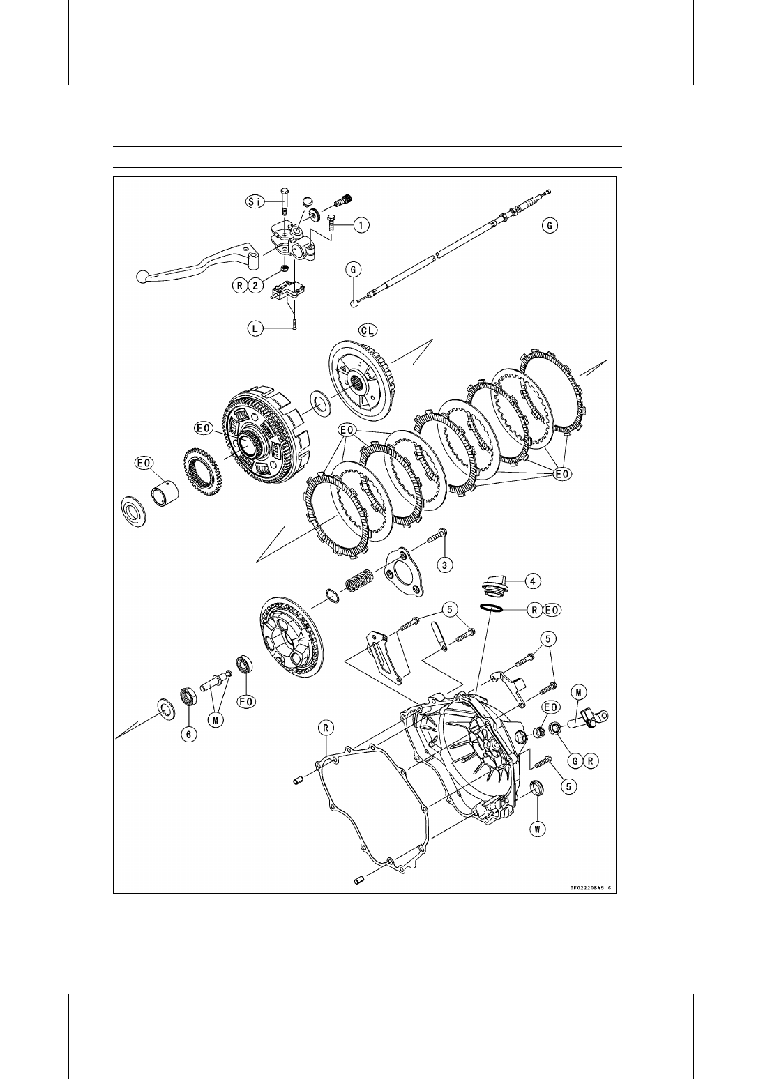
CLUTCH 6-3

Exploded View

Torque

No.

Fastener

N·m

kgf·m

ft·lb

Remarks

1 Clutch Lever Clamp Bolt

8.8

0.90

78 in·lb

2 Clutch Lever Pivot Bolt Locknut

1.6

0.16

14 in·lb

R

3 Clutch Stopper Bolts

8.83

0.900

78.2 in·lb

4 Oil Filler Plug

Hand-Tighten

5 Clutch Cover Bolts

9.8

1.0

87 in·lb

6 Clutch Hub Nut

132

13.5

97.4

CL: Apply cable lubricant.

EO: Apply engine oil.

G: Apply grease.

M: Apply molybdenum disulfide grease.

R: Replacement Parts

Si: Apply silicone grease.

W: Apply water.

6-4 CLUTCH

Specifications

Item

Standard

Service Limit

Clutch Lever Free Play

2

3 mm (0.08

0.12 in.)

– – –

Clutch

Friction Plate Thickness

2.92

3.08 mm (0.115

0.121 in.)

2.6 mm (0.10 in.)

Friction and Steel Plate Warp

0.15 mm (0.0059 in.) or less

0.3 mm (0.012 in.)

Clutch Spring Free Length

42.0 mm (1.65 in.)

40.2 mm (1.58 in.)

CLUTCH 6-5

Special Tool and Sealant

Clutch Holder:
57001-1243

Liquid Gasket, TB1211F:
92104-0004

6-6 CLUTCH

Clutch Lever and Cable

Clutch Lever Free Play Inspection

Refer to the Clutch Operation Inspection in the Periodic
Maintenance chapter.

Clutch Lever Free Play Adjustment

Refer to the Clutch Operation Inspection in the Periodic
Maintenance chapter.

Clutch Cable Removal

Remove the right middle fairing (see Middle Fairing Re-
moval in the Frame chapter).

Loosen the locknut [A] at the clutch lever, and screw in
the adjuster [B].

Line up the slots [C] in the clutch lever, locknut and ad-
juster, and then free the cable from the lever.

Slide the dust cover [A] at the clutch cable lower end out
of place.

Remove the clutch cable lower from the cable holder [B]
loosening the locknuts [C].

Free the clutch inner cable tip from the clutch release
lever.

Pull the clutch cable out of the frame.

Clutch Cable Installation

Run the clutch cable correctly (see Cable, Wire, and Hose
Routing section in the Appendix chapter).

Adjust the clutch cable (see Clutch Operation Inspection
in the Periodic Maintenance chapter).

Clutch Cable Lubrication

Refer to the Chassis Parts Lubrication in the Periodic
Maintenance chapter.

Clutch Lever Installation

Install the clutch lever so that the mating surface [A] of the
clutch lever is aligned with the punch mark [B].

Tighten:

Torque - Clutch Lever Clamp Bolt: 8.8 N·m (0.90 kgf·m, 78

in·lb)

CLUTCH 6-7

Clutch Cover

Clutch Cover Removal

Drain the engine oil (see Engine Oil Change in the Peri-
odic Maintenance chapter).

Remove:

Right Lower Fairing (see Lower Fairing Removal in the
Frame chapter)
Clutch Cable Lower End [A]
Clutch Cover Bolts [B]
Bolt [C]

Turn the release lever [A] toward the rear as shown in the
figure, and remove the clutch cover [B].

About 90° [C]

Clutch Cover Installation

Be sure to dowel pins [A].

Clean off any oil or dirt and apply liquid gasket to the area
[B] where the mating surface of the crankcase touches
the clutch cover gasket.

Sealant - Liquid Gasket, TB1211F: 92104-0004

Replace the clutch cover gasket with a new one and install
it.

Install:

Clutch Cover [A]
Clutch Cable Bracket [B]
Clamp [C]
Bracket [D]

Tighten the clutch cover bolts [E] (L = 25 mm) and [F] (L=
30 mm).

Torque - Clutch Cover Bolts: 9.8 N·m (1.0 kgf·m, 87 in·lb)

Tighten the bolt [G].

Install the removed parts (see appropriate chapters).

Release Shaft Removal

NOTICE

Do not remove the clutch release lever and shaft
assembly unless it is absolutely necessary. If re-
moved, the oil seal replacement may be required.

Remove the clutch cover (see Clutch Cover Removal).

Pull the lever and shaft assembly straight out of the clutch
cover.

6-8 CLUTCH

Clutch Cover

Release Shaft Installation

Apply grease to the oil seal lips on the upper ridge of the
clutch cover.

Apply engine oil to the needle bearing in the hole of the
clutch cover.

Apply molybdenum disulfide grease to the pusher-holding
portion [A] on the release shaft.

Insert the release shaft straight into the upper hole of the
clutch cover.

NOTICE

When inserting the release shaft, be careful not to
remove the spring of the oil seal.

Clutch Cover Disassembly

Remove:

Oil Seal [A]
Needle Bearing [B]
Oil Level Inspection Window

Clutch Cover Assembly

Replace the needle bearing and oil seal with new ones.

NOTE

Install the needle bearing so that the manufacture’s
mark face out.

Install the needle bearing [A] and oil seal [B] position as
shown.

Press the needle bearing so that the bearing surface [C]
is flush with the housing end of clutch cover [D].

Press the oil seal until the bottom [E].

Apply grease to the oil seal lips.

Apply water to the rubber of the oil level inspection win-
dow [A] and press [B] it so that the ring [C] faces outside.

CLUTCH 6-9

Clutch

Clutch Removal

Remove:

Clutch Cover (see Clutch Cover Removal)
Clutch Stopper Bolts [A]

Loosen the clutch stopper bolts evenly with little by little
to prevent tilting the clutch stopper plate.

NOTICE

Do not loosen the one or two clutch stopper plate
bolt at once to prevent clutch stopper plate warpage
by the spring force.

Remove:

Clutch Stopper Plate [B]
Clutch Springs
Clutch Pressure Plate [C] (with Bearing and Pusher [D])

Remove:

Spring Seats [A]

Remove:

Friction Plates and Steel Plates
Clutch Hub Nut [A]

Holding the clutch hub [B], remove the nut and washer.

Special Tool - Clutch Holder [C]: 57001-1243

Remove:

Clutch Hub
Spacer
Bushing
Clutch Housing
Thrust Spacer

Clutch Installation

Install the thrust spacer [A] so that the chamfer side [B]
faces inward.

6-10 CLUTCH

Clutch

Install the bushing [A], clutch housing [B], spacer, clutch
hub, washer and clutch hub nut.

Holding the clutch hub [A], tighten the clutch hub nut [B].

Special Tool - Clutch Holder [C]: 57001-1243

Torque - Clutch Hub Nut: 132 N·m (13.5 kgf·m, 97.4 ft·lb)

Make sure the friction plates [A] [B] and steel plates [C] [D]
in relations to the differences and installation positions.

The friction plates [B] are no cutout [E] on the tangs and
the friction plates [A] have the cutout [F] on the tangs. The
steel plate [D] has the larger inner diameter than others.

NOTICE

If new dry friction plates and steel plates are in-
stalled, apply engine oil to the surfaces of each
plate to avoid clutch plate seizure.

Install the three friction plates [A] and three steel plates
[C] alternately, and then install the one friction plate [B] to
the outside [G] position as shown.

The one friction plate [B] and steel plate [D] positioned to
the outside should be install later together with the clutch
pressure plate.

Apply molybdenum disulfide grease to the pusher end [A].

Install the pusher [B] into the drive shaft [C].

CLUTCH 6-11

Clutch

Apply engine oil to the sliding surfaces of the bearing [A].

Put the friction plate [B] (no cutout) and steel plate [C]
(larger inner diameter) on the clutch pressure plate [D],
and install them.

Align the tangs [A] on the friction plates (no cutout) with
hole [B] on the clutch pressure plate [C] to install them
into the clutch housing [D].

Install:

Spring Seats [A]

Install:

Clutch Springs
Clutch Stopper Plate [A]
Clutch Stopper Bolts [B]

Tighten the clutch stopper plate bolts evenly with little by
little to prevent tilting the clutch stopper plate.

NOTICE

Do not tighten the one or two clutch stopper plate
bolt at once to prevent clutch stopper plate warp
age by the spring force.

Tighten:

Torque - Clutch Stopper Bolts: 8.83 N·m (0.900 kgf·m, 78.2

in·lb)

Install the clutch cover (see Clutch Cover Installation).

6-12 CLUTCH

Clutch

Clutch Plate Wear and Damage Inspection

Visually inspect the friction and steel plates for signs of
seizure, overheating (discoloration), or uneven wear.

Measure the thickness of each friction plate [A] at several
points.
If any plates show signs of damage, or if they have worn
past the service limit, replace them with new ones.

Friction Plate Thickness

Standard:

2.92

3.08 mm (0.115

0.121 in.)

Service Limit:

2.6 mm (0.10 in.)

Clutch Plate Warp Inspection

Place each friction plate or steel plate on a surface plate
and measure the gap between the surface plate [A] and
each friction plate or steel plate [B] with a thickness gauge
[C]. The gap is the amount of friction or steel plate warp.
If any plate is warped over the service limit, replace it with
a new one.

Friction and Steel Plate Warp

Standard:

0.15 mm (0.0059 in.) or less

Service Limit:

0.3 mm (0.012 in.)

Clutch Spring Free Length Inspection

Measure the free length of the clutch springs [A].
If any spring is shorter than the service limit, it must be
replaced.

Clutch Spring Free Length

Standard:

42.0 mm (1.65 in.)

Service Limit:

40.2 mm (1.58 in.)

Clutch Housing Finger Inspection

Visually inspect the clutch housing fingers [A] where the
friction plate tangs [B] hit.
If they are badly worn or if there are groove cuts where the
tangs hit, replace the housing. Also, replace the friction
plates if their tangs are damaged.

CLUTCH 6-13

Clutch

Clutch Housing Spline Inspection

Visually inspect where the teeth [A] on the steel plates
wear against the clutch hub splines [B].
If there are notches worn into the splines, replace the
clutch hub. Also, replace the steel plates if their teeth are
damaged.

Clutch Pressure Plate and Clutch Hub Inspection

Visually inspect the contact areas [A] of the clutch pres-
sure plate [B] and clutch hub [C] for damage.
If the contact areas are damaged replace them with new
ones.

ENGINE LUBRICATION SYSTEM 7-1

7

Engine Lubrication System

Table of Contents

Exploded View........................................................................................................................

7-2

Engine Oil Flow Chart.............................................................................................................

7-4

Specifications .........................................................................................................................

7-5

Special Tools and Sealant ......................................................................................................

7-6

Engine Oil and Oil Filter..........................................................................................................

7-7

Oil Level Inspection...........................................................................................................

7-7

Engine Oil Change............................................................................................................

7-7

Oil Filter Replacement ......................................................................................................

7-7

Oil Pan Removal ...............................................................................................................

7-8

Oil Pan Installation ............................................................................................................

7-8

Oil Screen Removal ..........................................................................................................

7-8

Oil Screen Installation .......................................................................................................

7-8

Oil Screen Cleaning ..........................................................................................................

7-9

Oil Pressure Relief Valve........................................................................................................

7-10

Oil Pressure Relief Valve Removal ...................................................................................

7-10

Oil Pressure Relief Valve Installation ................................................................................

7-10

Oil Pressure Relief Valve Inspection.................................................................................

7-10

Oil Pump.................................................................................................................................

7-11

Oil Pump Removal ............................................................................................................

7-11

Oil Pump Installation .........................................................................................................

7-11

Oil Pressure Measurement.....................................................................................................

7-13

Oil Pressure Measurement ...............................................................................................

7-13

Oil Pressure Switch ................................................................................................................

7-14

Oil Pressure Switch Removal ...........................................................................................

7-14

Oil Pressure Switch Installation ........................................................................................

7-14

7-2 ENGINE LUBRICATION SYSTEM

Exploded View

ENGINE LUBRICATION SYSTEM 7-3

Exploded View

Torque

No.

Fastener

N·m

kgf·m

ft·lb

Remarks

1

Oil Pipe Banjo Bolts (Outside)

19.6

2.00

14.5

2

Oil Pipe Bolt

9.8

1.0

87 in·lb

L

3

Oil Breather Mounting Bolts

9.8

1.0

87 in·lb

L

4

Oil Filter

17.5

1.78

12.9

EO, R

5

Crankcase Oil Passage Plugs

20

2.0

15

L

6

Spur Gear Mounting Bolt

9.8

1.0

87 in·lb

L

7

Oil Pump Mounting Bolts

9.8

1.0

87 in·lb

8

Oil Pressure Switch Terminal Bolt

1.5

0.15

13 in·lb

G

9

Oil Pressure Switch

15

1.5

11

SS

10

Oil Pipe Banjo Bolt (Inside)

12

1.2

106 in·lb

11

Oil Pressure Relief Valve

15

1.5

11

L

12

Oil Pan Bolts

9.8

1.0

87 in·lb

13

Engine Oil Drain Bolt

19.6

2.00

14.5

EO: Apply engine oil.

G: Apply grease.

L: Apply a non-permanent locking agent.

MO: Apply molybdenum disulfide grease oil solution.

(mixture of the engine oil and molybdenum disulfide grease in a weight ratio 10:1)

R: Replacement Parts

SS: Apply silicone sealant.

7-4 ENGINE LUBRICATION SYSTEM

Engine Oil Flow Chart

ENGINE LUBRICATION SYSTEM 7-5

Specifications

Item

Standard

Engine Oil

Type

API SG, SH, SJ, SL or SM with JASO MA, MA1 or MA2

Viscosity

SAE 10W-40

Capacity

2.0 L (2.1 US qt) (when filter is not removed)
2.2 L (2.3 US qt) (when filter is removed)
2.4 L (2.5 US qt) (when engine is completely dry)

Level

Between upper and lower level lines (Wait 2

3 minutes

after idling or running)

Oil Pressure Measurement

Oil Pressure

98

147 kPa (1.0

1.5 kgf/cm², 14

21 psi) at 4 000

r/min (rpm), Oil Temperature 90°C (194°F)

7-6 ENGINE LUBRICATION SYSTEM

Special Tools and Sealant

Oil Pressure Gauge, 10 kgf/cm²:
57001-164

Oil Pressure Gauge Adapter, PT3/8:
57001-1233

Clutch Holder 1:
57001-1507

Liquid Gasket, TB1211:
56019-120

ENGINE LUBRICATION SYSTEM 7-7

Engine Oil and Oil Filter

WARNING

Vehicle operation with insufficient, deteriorated,
or contaminated engine oil will cause accelerated
wear and may result in engine seizure, accident,
and injury. Check the oil level before each use and
change the oil and filter according to the periodic
maintenance chart.

Oil Level Inspection

Check that the engine oil level is between the upper [A]
and lower [B] levels in the oil level inspection window.

NOTE

Situate the motorcycle so that it is perpendicular to the
ground.

If the motorcycle has just been used, wait several min-
utes for all the oil to drain down.

If the oil has just been changed, start the engine and
run it for several minutes at idle speed. This fills the oil
filter with oil. Stop the engine, then wait several minutes
until the oil settles.

NOTICE

Racing the engine before the oil reaches every part
can cause engine seizure.
If the engine oil gets extremely low or if the oil pump
or oil passages clog up or otherwise do not function
properly, the oil pressure warning indicator light
will light. If this light stays on when the engine is
running above idle speed, stop the engine immedi-
ately and find the cause.

If the oil level is too high, remove the excess oil, using a
syringe or some other suitable device.
If the oil level is too low, add the correct amount of oil
through the oil filler opening. Use the same type and
make of oil that is already in the engine.

NOTE

If the engine oil type and make are unknown, use any
brand of the specified oil to top off the level in preference
to running the engine with the oil level low. Then at your
earliest convenience, change the oil completely.

Engine Oil Change

Refer to the Engine Oil Change in the Periodic Mainte-
nance chapter.

Oil Filter Replacement

Refer to the Oil Filter Replacement in the Periodic Main-
tenance chapter.

7-8 ENGINE LUBRICATION SYSTEM

Engine Oil and Oil Filter

Oil Pan Removal

Drain the engine oil (see Engine Oil Change in the Peri-
odic Maintenance chapter).

Remove:

Exhaust Pipe (see Exhaust Pipe Removal in the Engine
Top End chapter)
Oil Pan Bolts [A] with Bracket
Oil Pan [B]
Gasket

Remove the following parts if necessary.

Oil Screen (see Oil Screen Removal)
Oil Pressure Relief Valve (see Oil Pressure Relief Valve
Removal)

Oil Pan Installation

Install the following parts if removed.

Oil Pressure Relief Valve (see Oil Pressure Relief Valve
Installation)
Oil Screen (see Oil Screen Installation)

Replace the oil pan gasket with a new one.

Install the brackets [A] as shown in the figure.

Tighten:

Torque - Oil Pan Bolts [B]: 9.8 N·m (1.0 kgf·m, 87 in·lb)

Install the removed parts (see appropriate chapters).

Oil Screen Removal

Remove:

Oil Pan (see Oil Pan Removal)
Oil Screen [A]

Oil Screen Installation

Clean the oil screen (see Oil Screen Cleaning).

Replace the O-ring [A] with a new one, and install it.

Apply grease to the O-ring.

Install the oil screen [B] so that its guide portion [C] fits
the crankcase rib [D].

ENGINE LUBRICATION SYSTEM 7-9

Engine Oil and Oil Filter

Oil Screen Cleaning

Remove the oil screen (see Oil Screen Removal).

Clean the oil screen with a high flash-point solvent and
remove the particles stuck.

Blow away the particles by applying compressed air [A]
from the inside to the outside (from the clean side to the
dirty side).

WARNING

Gasoline and low flash-point solvents can be
flammable and/or explosive and cause severe
burns. Clean the screen in a well-ventilated area,
and take care that there are no sparks or flame
anywhere near the working area; this includes any
appliance with a pilot light. Do not use gasoline or
a low flash-point solvent to clean the screen.

NOTE

While cleaning the screen, check for any metal particles
that might indicate internal engine damage.

Check the screens carefully for any damage.
If the screen is damaged, replace the oil screen.

7-10 ENGINE LUBRICATION SYSTEM

Oil Pressure Relief Valve

Oil Pressure Relief Valve Removal

Remove:

Oil Pan (see Oil Pan Removal)
Oil Pressure Relief Valve [A]

Oil Pressure Relief Valve Installation

Apply a non-permanent locking agent to the threads of
the oil pressure relief valve, and tighten it.

NOTICE

Do not apply too much non-permanent locking
agent to the threads. This may block the oil pas-
sage.

Torque - Oil Pressure Relief Valve: 15 N·m (1.5 kgf·m, 11

ft·lb)

Install the removed parts (see appropriate chapters).

Oil Pressure Relief Valve Inspection

Check to see if the valve [A] slides smoothly when push-
ing it in with a wooden or other soft rod, and see if it comes
back to its seat by spring [B] pressure.

NOTE

Do not try to disassemble the pressure relief valve. The
pressure relief valve inspection should be checked in its
assembled condition.

If any rough spots are found during above inspection,
wash the valve clean with a high flash-point solvent and
blow out any foreign particles that may be in the valve with
compressed air.

WARNING

Gasoline and low flash-point solvents can be
flammable and/or explosive and cause severe
burns. Clean the relief valve in a well-ventilated
area, and take care that there is no spark or flame
anywhere near the working areas.

Do not use

gasoline or low flash-point solvents to clean the
relief valve.

If any problem does not improve, replace the pressure
relief valve as an assembly.

ENGINE LUBRICATION SYSTEM 7-11

Oil Pump

Oil Pump Removal

Remove:

Clutch (see Clutch Removal in the Clutch chapter)
Spur Gear Mounting Bolt [A]

Special Tool - Clutch Holder 1 [B]: 57001-1507

Place a clean cloth under the oil pump cover [A].

Remove:

Oil Pump Mounting Bolts [B]
Oil Pump Cover

Remove:

Oil Pump Shaft [A] with Inner Rotor [B]
Outer Rotor [C]

Oil Pump Installation

Assemble the pin [A] and rotor [B] to the oil pump shaft
[C], aligning the pin with the grooves on the rotor.

Apply molybdenum disulfide oil solution to the sliding sur-
faces of the oil pump shaft.

Install the outer rotor [A] into the crankcase.

Turn the oil pump shaft so that the projection [B] in its shaft
fits into the slot [C] of the water pump shaft.

7-12 ENGINE LUBRICATION SYSTEM

Oil Pump

Install the oil pump cover [A] so that the dowel pin [B] fits
into the hole [C] of the crankcase.

Tighten:

Torque - Oil Pump Mounting Bolts [A]: 9.8 N·m (1.0 kgf·m,

87 in·lb)

Install the spur gear [A] onto the oil pump shaft [B] with its
projecting side [C] facing to the oil pump.

Apply a non-permanent locking agent to the threads of
the spur gear mounting bolt [A].

Tighten the spur gear mounting bolt.

Special Tool - Clutch Holder 1 [B]: 57001-1507

Torque - Spur Gear Mounting Bolt: 9.8 N·m (1.0 kgf·m, 87

in·lb)

ENGINE LUBRICATION SYSTEM 7-13

Oil Pressure Measurement

Oil Pressure Measurement

Remove the right lower fairing (see Lower Fairing Re-
moval in the Frame chapter).

Remove the crankcase oil passage plug, and attach the
adapter [A] and gauge [B] to the plug hole.

Special Tools - Oil Pressure Gauge, 10 kgf/cm²: 57001-164

Oil Pressure Gauge Adapter, PT3/8: 57001

-1233

Start the engine and warm up the engine.

Run the engine at the specified speed, and read the oil
pressure gauge.
If the reading is much lower than the standard, check
the oil pump, relief valve, and/or crankshaft bearing in-
sert wear immediately.
If the reading is much higher than the standard, check the
oil passages for clogging.

Oil Pressure

Standard: 98

147 kPa (1.0

1.5 kgf/cm², 14

21 psi)

at 4 000 r/min (rpm), Oil Temperature 90°C
(194°F)

Stop the engine.

Remove the oil pressure gauge and adapter.

WARNING

Hot oil can cause severe burns. Beware of hot en-
gine oil that will drain through the oil passage when
the gauge adapter is removed.

Apply a non-permanent locking agent to the crankcase oil
passage plug, and install it.

Tighten:

Torque - Crankcase Oil Passage Plug: 20 N·m (2.0 kgf·m,

15 ft·lb)

Install the right lower fairing (see Lower Fairing Installa-
tion in the Frame chapter).

7-14 ENGINE LUBRICATION SYSTEM

Oil Pressure Switch

Oil Pressure Switch Removal

Drain:

Engine Oil (see Engine Oil Change in the Periodic Main-
tenance chapter)

Remove:

Right Lower Fairing (see Lower Fairing Removal in the
Frame chapter)
Switch Cover [A]
Switch Terminal Bolt [B]
Oil Pressure Switch [C]

Oil Pressure Switch Installation

Clean off any oil or dirt and apply silicone sealant to the
threads of the oil pressure switch [A] and tighten it.

Sealant - Liquid Gasket, TB1211: 56019-120

Torque - Oil Pressure Switch: 15 N·m (1.5 kgf·m, 11 ft·lb)

Apply grease to the both sides of the switch lead terminal
[B].

Connect the switch lead terminal bolt [C] to the switch
terminal.

Tighten:

Torque - Oil Pressure Switch Terminal Bolt: 1.5 N·m (0.15

kgf·m, 13 in·lb)

NOTE

Apply a small amount of grease to the terminal so
that grease should not close two breather holes [A] for
switch diaphragm.

Install:

Switch Cover
Right Lower Fairing (see Lower Fairing Installation in the
Frame chapter)

Fill the engine with engine oil (see Engine Oil Change in
the Periodic Maintenance chapter).

ENGINE REMOVAL/INSTALLATION 8-1

8

Engine Removal/Installation

Table of Contents

Exploded View........................................................................................................................

8-2

Engine Removal/Installation ...................................................................................................

8-4

Engine Removal................................................................................................................

8-4

Engine Installation.............................................................................................................

8-5

8-2 ENGINE REMOVAL/INSTALLATION

Exploded View

ENGINE REMOVAL/INSTALLATION 8-3

Exploded View

Torque

No.

Fastener

N·m

kgf·m

ft·lb

Remarks

1 Front Upper Engine Mounting Bolts

69

7.0

51

2 Front Lower Engine Mounting Nut

69

7.0

51

3 Front Middle Engine Mounting Nut

44

4.5

32

4 Rear Engine Mounting Nuts

69

7.0

51

8-4 ENGINE REMOVAL/INSTALLATION

Engine Removal/Installation

Engine Removal

Support the rear part of the swingarm with a stand.

Squeeze the brake lever slowly and hold it with a band
[A].

WARNING

Motorcycle may fall over unexpectedly resulting in
an accident or injury. Be sure to hold the front brake
when removing the engine.

NOTICE

Be sure to hold the front brake when removing the
engine, or the motorcycle may fall over. The engine
or the motorcycle could be damaged.

Drain:

Engine Oil (see Engine Oil Change in the Periodic Main-
tenance chapter)
Coolant (see Coolant Change in the Periodic Mainte-
nance chapter)

Remove:

Middle Fairings (see Middle Fairing Removal in the
Frame chapter)
Fuel Tank (see Fuel Tank Removal in the Fuel System
(DFI) chapter)
Coolant Reserve Tank (see Coolant Reserve Tank Re-
moval in the Cooling System chapter)
Radiator (see Radiator and Radiator Fan Removal in the
Cooling System chapter)
Exhaust Pipe (see Exhaust Pipe Removal in the Engine
Top End chapter)
Air Switching Valve (see Air Switching Valve Removal in
the Engine Top End chapter)
Throttle Body Assy (see Throttle Body Assy Removal in
the Fuel System (DFI) chapter)
Stick Coils (see Stick Coil Removal in the Electrical Sys-
tem chapter)
Shift Lever (see Shift Pedal Removal in the Crank-
shaft/Transmission chapter)
Engine Sprocket (see Engine Sprocket Removal in the
Final Drive chapter)

Disconnect:

Oil Pressure Switch Lead Terminal [A]
Engine Ground Cable Terminal [B]
Starter Motor Cable Terminal [C]

Remove:

Clutch Cable Lower End [D] (see Clutch Cable Removal
in the Clutch chapter)
Bracket [E]

ENGINE REMOVAL/INSTALLATION 8-5

Engine Removal/Installation

Disconnect:

Neutral Switch Lead Terminal [A]
Crankshaft Sensor Lead Connector [B]
Alternator Lead Connector [C]

Remove:

Breather Hose [D]
Connector Mounting Bracket Bolts [E]

Support the engine with a suitable stand [A].

Put planks [B] onto the suitable stand for engine balance.

Remove:

Front Lower Engine Mounting Nut [A] and Bolt
Front Middle Engine Mounting Nut [B] and Bolt
Front Lower Engine Mounting Bracket [C]
Front Upper Engine Mounting Nuts and Bolts [D] (Both
Sides)
Front Upper Engine Mounting Brackets [E] (Both Sides)
Side Dampers (Both Sides)

Remove:

Rear Engine Mounting Nuts [A] and Bolts
Engine [B]

Engine Installation

Support the engine with a suitable stand.

Put planks onto the suitable stand for engine balance.


Content      ..     7      8      9      10     ..