Kawasaki Ninja 300 / Ninja 300 ABS Motorcycle. Service Manual (2013) - page 7
 

  Index      Manuals     Kawasaki Ninja 300 / Ninja 300 ABS Motorcycle. Service Manual (2013)


Search            copyright infringement  


Content      ..     5      6      7      8     ..


Kawasaki Ninja 300 / Ninja 300 ABS Motorcycle. Service Manual (2013) - page 7


3-116 FUEL SYSTEM (DFI)

Fuel Tank

Fuel Tank Inspection

Open the tank cap.

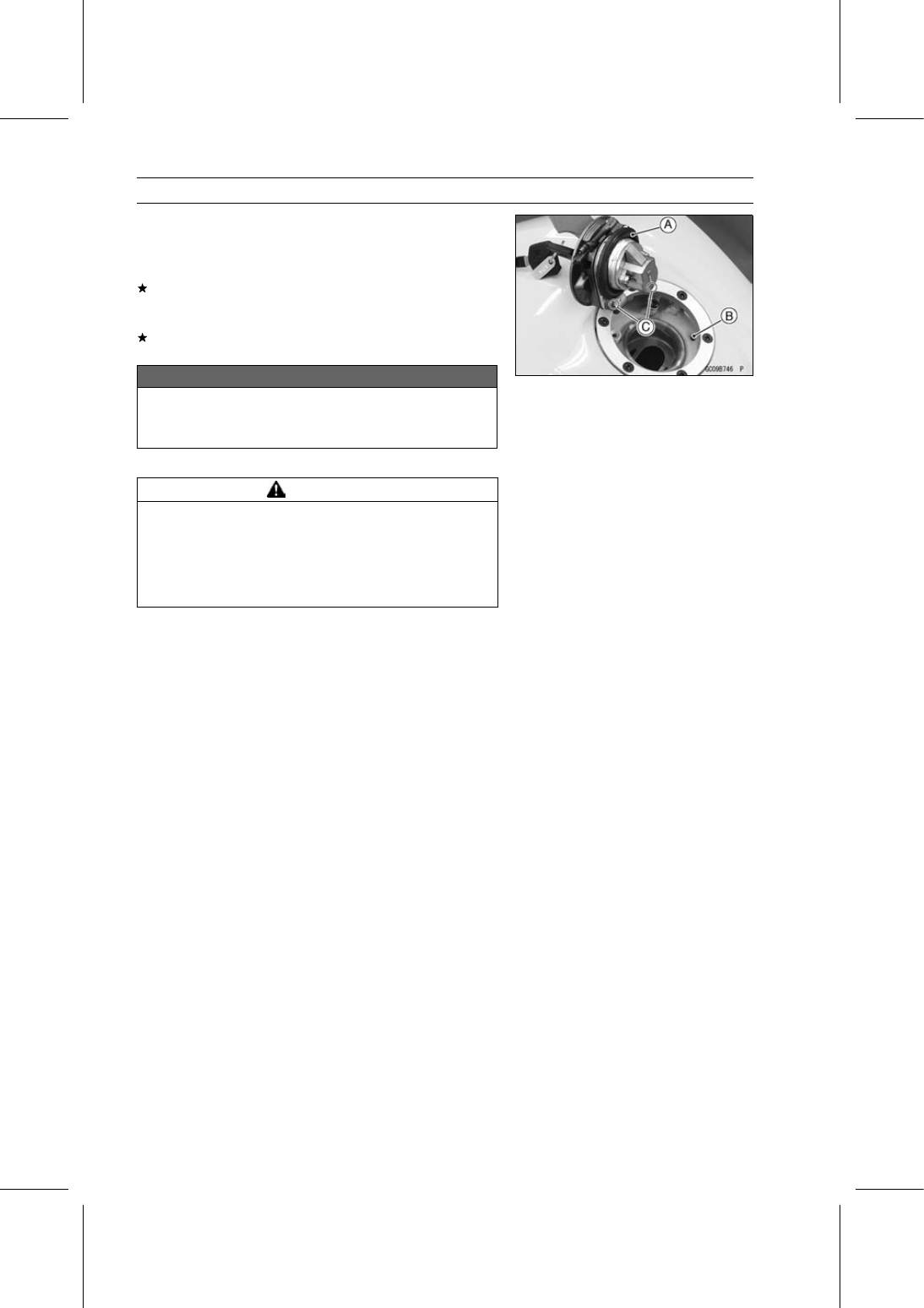
Visually inspect the gasket [A] on the tank cap for any
damage.
Replace the gasket if it is damaged.

Check to see if the water drain hole [B] in the tank is not
clogged. Check the tank cap breather also.
If they are clogged, remove the tank and drain it, and then
blow the breather free with compressed air.

NOTICE

Do not apply compressed air to the air vent holes
[C] in the tank cap. This could cause damage and
clogging of the labyrinth in the cap.

Fuel Tank Cleaning

WARNING

Gasoline and low flash-point solvents can be
flammable and/or explosive and cause severe
burns. Clean the tank in a well-ventilated area, and
take care that there are no sparks or flame any-
where near the working area. Do not use gasoline
or low flash-point solvents to clean the tank.

Remove:

Fuel Tank (see Fuel Tank Removal)
Fuel Pump (see Fuel Pump Removal)

Pour some high flash-point solvent into the fuel tank and
shake the tank to remove dirt and fuel deposits.

Draw the solvent out of the fuel tank.

Dry the tank with compressed air.

Install:

Fuel Pump (see Fuel Pump Installation)
Fuel Tank (see Fuel Tank Installation)

FUEL SYSTEM (DFI) 3-117

Evaporative Emission Control System (CAL Model)

The Evaporative Emission Control System routes fuel va-

pors from the fuel system into the running engine or stores
the vapors in a canister [A] when the engine is stopped.
Although no adjustments are required, a thorough visual
inspection must be made at the intervals specified by the
Periodic Maintenance Chart.

Parts Removal/Installation

WARNING

Gasoline is extremely flammable and can be ex-
plosive under certain conditions. Turn the ignition
switch off. Do not smoke. Make sure the area is
well-ventilated and free from any source of flame
or sparks; this includes any appliance with a pilot
light.

NOTICE

If gasoline, solvent, water or any other liquid enters
the canister, the canister’s vapor absorbing capac-
ity is greatly reduced. If the canister does become
contaminated, replace it with a new one.

Connect the hoses according to the diagram of the sys-
tem (see Cable, Wire, and Hose Routing section in the
Appendix chapter). Make sure they do not get pinched or
kinked.

Hose Inspection

Refer to the Evaporative Emission Control System In-
spection (CAL Model) in the Periodic Maintenance chap-
ter.

Purge Valve Inspection

Refer to the Purge Valve Inspection.

Canister Inspection

Refer to the Evaporative Emission Control System In-
spection (CAL Model) in the Periodic Maintenance chap-
ter.

COOLING SYSTEM 4-1

4

Cooling System

Table of Contents

Exploded View........................................................................................................................

4-2

Coolant Flow Chart.................................................................................................................

4-4

Specifications .........................................................................................................................

4-6

Coolant ...................................................................................................................................

4-7

Coolant Deterioration Inspection.......................................................................................

4-7

Coolant Level Inspection...................................................................................................

4-7

Coolant Draining ...............................................................................................................

4-7

Coolant Filling ...................................................................................................................

4-7

Pressure Testing ...............................................................................................................

4-7

Cooling System Flushing ..................................................................................................

4-8

Coolant Reserve Tank Removal .......................................................................................

4-8

Coolant Reserve Tank Installation ....................................................................................

4-8

Water Pump............................................................................................................................

4-9

Water Pump Cover Removal ............................................................................................

4-9

Water Pump Cover Installation .........................................................................................

4-9

Water Pump Removal.......................................................................................................

4-9

Water Pump Installation....................................................................................................

4-10

Water Pump Inspection.....................................................................................................

4-10

Mechanical Seal Inspection ..............................................................................................

4-10

Mechanical Seal Removal ................................................................................................

4-10

Mechanical Seal Installation .............................................................................................

4-11

Impeller Assembly.............................................................................................................

4-11

Water Pump Impeller Inspection.......................................................................................

4-11

Radiator ..................................................................................................................................

4-12

Radiator and Radiator Fan Removal ................................................................................

4-12

Radiator and Radiator Fan Installation .............................................................................

4-12

Radiator Inspection ...........................................................................................................

4-13

Radiator Cap Inspection ...................................................................................................

4-13

Radiator Filler Neck Inspection .........................................................................................

4-14

Thermostat .............................................................................................................................

4-15

Thermostat Removal.........................................................................................................

4-15

Thermostat Installation......................................................................................................

4-15

Thermostat Housing Removal ..........................................................................................

4-15

Thermostat Housing Installation .......................................................................................

4-15

Thermostat Inspection ......................................................................................................

4-16

Hoses and Pipes ....................................................................................................................

4-17

Hose Installation ...............................................................................................................

4-17

Hose Inspection ................................................................................................................

4-17

Water Temperature Sensor ....................................................................................................

4-18

Water Temperature Sensor Removal/Installation .............................................................

4-18

Water Temperature Sensor Inspection .............................................................................

4-18

4-2 COOLING SYSTEM

Exploded View

COOLING SYSTEM 4-3

Exploded View

Torque

No.

Fastener

N·m

kgf·m

ft·lb

Remarks

1

Thermostat Housing Mounting Bolts

9.8

1.0

87 in·lb

2

Reserve Tank Bolts

4.0

0.41

35 in·lb

3

Reserve Tank Cap

Hand-Tighten

4

Radiator Cap Bracket Bolt

9.8

1.0

87 in·lb

5

Radiator Bolts

9.8

1.0

87 in·lb

6

Radiator Fan Assy Mounting Bolts

8.4

0.86

74 in·lb

7

Water Hose Clamp Screws

3.0

0.31

27 in·lb

8

Thermostat Cover Bolts

9.8

1.0

87 in·lb

9

Water Temperature Sensor

12

1.2

106 in·lb

10 Coolant Drain Bolt (Cylinder)

5.9

0.60

52 in·lb

11 Left Middle Fairing Bracket Bolts

9.8

1.0

87 in·lb

HL

12 Water Hose Fitting Bolts

9.8

1.0

87 in·lb

13 Water Pump Cover Bolts

9.8

1.0

87 in·lb

14 Water Pump Impeller

9.8

1.0

87 in·lb

15 Water Pump Bolts

9.8

1.0

87 in·lb

16 Coolant Drain Bolt (Water Pump)

9.8

1.0

87 in·lb

17 Water Pipe Bolt

9.8

1.0

87 in·lb

G: Apply grease.

HL: Apply a non-permanent locking agent (High Strength).

R: Replacement Parts

4-4 COOLING SYSTEM

Coolant Flow Chart

COOLING SYSTEM 4-5

Coolant Flow Chart

Permanent type antifreeze is used as a coolant to protect the cooling system from rust and corrosion.

When the engine starts, the water pump turns and the coolant circulates.

The thermostat is a wax pellet type which opens or closes with coolant temperature changes. The

thermostat continuously changes its valve opening to keep the coolant temperature at the proper level.
When coolant temperature is less than 63.5

66.5°C (146

152°F), the thermostat closes so that the

coolant flow is restricted through the air bleeder hole, causing the engine to warm up more quickly.
When coolant temperature is more than 63.5

66.5°C (146

152°F), the thermostat opens and the

coolant flows.

When the coolant temperature goes up beyond 103°C (217°F), the radiator fan relay conducts to

operate the radiator fan. The radiator fan draws air through the radiator core when there is not suffi-
cient air flow such as at low speeds. This increases up the cooling action of the radiator. When the
coolant temperature is below 98°C (208°F), the fan relay opens and the radiator fan stops.

In this way, this system controls the engine temperature within narrow limits where the engine op-

erates most efficiently even if the engine load varies.

The system is pressurized by the radiator cap to suppress boiling and the resultant air bubbles

which can cause engine overheating. As the engine warms up, the coolant in the radiator and the
water jacket expands. The excess coolant flows through the radiator cap and hose to the reserve tank
to be stored there temporarily. Conversely, as the engine cools down, the coolant in the radiator and
the water jacket contracts, and the stored coolant flows back to the radiator from the reserve tank.

The radiator cap has two valves. One is a pressure valve which holds the pressure in the system

when the engine is running. When the pressure exceeds 93

123 kPa (0.95

1.25 kgf/cm², 13

18

psi), the pressure valve opens and releases the pressure to the reserve tank. As soon as pressure
escapes, the valve closes, and keeps the pressure at 93

123 kPa (0.95

1.25 kgf/cm², 13

18 psi).

When the engine cools down, another small valve (vacuum valve) in the cap opens. As the coolant
cools, the coolant contracts to form a vacuum in the system. The vacuum valve opens and allows the
coolant from the reserve tank to enter the radiator.

4-6 COOLING SYSTEM

Specifications

Item

Standard

Coolant Provided when Shipping

Type (Recommended)

Permanent type of antifreeze (soft water and ethylene
glycol plus corrosion and rust inhibitor chemicals for
aluminum engines and radiators)

Color

Green

Mixed Ratio

Soft water 50%, coolant 50%

Freezing Point

35°C (

31°F)

Total Amount

1.5 L (1.6 US qt) (reserve tank full level, including radiator
and engine)

Radiator Cap

Relief Pressure

93

123 kPa (0.95

1.25 kgf/cm², 13

18 psi)

Thermostat

Valve Opening Temperature

63.5

66.5°C (146

152°F)

Valve Full Opening Lift

6 mm (0.24 in.) or more at 80°C (176°F)

COOLING SYSTEM 4-7

Coolant

Coolant Deterioration Inspection

Remove the right middle fairing (see Middle Fairing Re-
moval in the Frame chapter).

Visually inspect the coolant [A] in the reserve tank.
If whitish cotton-like wafts are observed, aluminum parts
in the cooling system are corroded. If the coolant is
brown, iron or steel parts are rusting. In either case, flush
the cooling system.
If the coolant gives off an abnormal smell, check for a
cooling system leak. It may be caused by exhaust gas
leaking into the cooling system.

Coolant Level Inspection

Refer to the Coolant Level Inspection in the Periodic Main-
tenance chapter.

Coolant Draining

Refer to the Coolant Change in the Periodic Maintenance
chapter.

Coolant Filling

Refer to the Coolant Change in the Periodic Maintenance
chapter.

Pressure Testing

Remove the right middle fairing (see Middle Fairing Re-
moval in the Frame chapter).

Remove the radiator cap, and install a cooling system
pressure tester [A] on the filler neck.

NOTE

Wet the cap sealing surfaces with water or coolant to
prevent pressure leaks.

Build up pressure in the system carefully until the pres-
sure reaches 123 kPa (1.25 kgf/cm², 18 psi).

NOTICE

During pressure testing, do not exceed the pres-
sure for which the system is designed. The maxi-
mum pressure is 123 kPa (1.25 kgf/cm², 18 psi).

Watch the gauge for at least 6 seconds.
If the pressure holds steady, the system is all right.
If the pressure drops and no external source is found,
check for internal leaks. Droplets in the engine oil indicate
internal leakage. Check the cylinder head gasket and the
water pump.

Remove the pressure tester, replenish the coolant, and
install the radiator cap.

4-8 COOLING SYSTEM

Coolant

Cooling System Flushing

Over a period of time, the cooling system accumulates

rust, scale, and lime in the water jacket and radiator. When
this accumulation is suspected or observed, flush the cool-
ing system. If this accumulation is not removed, it will clog
up the water passage and considerable reduce the effi-
ciency of the cooling system.

Drain the cooling system (see Coolant Change in the Pe-
riodic Maintenance chapter).

Fill the cooling system with fresh water mixed with a flush-
ing compound.

NOTICE

Do not use a flushing compound which is harmful to
the aluminum engine and radiator. Carefully follow
the instructions supplied by the manufacturer of the
cleaning product.

Warm up the engine, and run it at normal operating tem-
perature for about ten minutes.

Stop the engine, and drain the cooling system.

Fill the system with fresh water.

Warm up the engine and drain the system.

Repeat the previous two steps once more.

Fill the system with a permanent type coolant and bleed
the air from the system (see Coolant Change in the Peri-
odic Maintenance chapter).

Coolant Reserve Tank Removal

Remove:

Right Middle Fairing (see Middle Fairing Removal in the
Frame chapter)
Bolts [A]
Cap [B]

Pour the coolant into a container.

Remove:

Hoses [C]
Coolant Reserve Tank [D]

Coolant Reserve Tank Installation

Installation is the reverse of removal.

Run the cable and hoses correctly (see Cable, Wire, and
Hose Routing section in the Appendix chapter).

Install the removed parts (see appropriate chapters).

Torque - Reserve Tank Bolts: 4.0 N·m (0.41 kgf·m, 35 in·lb)

COOLING SYSTEM 4-9

Water Pump

Water Pump Cover Removal

Drain the coolant (see Coolant Change in the Periodic
Maintenance chapter).

Remove:

Engine Sprocket Cover (see Engine Sprocket Removal
in the Final Drive chapter)
Water Pipe Bolt [A]
Left Middle Fairing Bracket Bolt [B]
Bracket [C]
Water Pipes [D]
Speed Sensor Bracket [E] (see Engine Sprocket Re-
moval in the Final Drive chapter)

Remove:

Water Pump Cover Bolts [A]
Water Pump Cover [B]

Water Pump Cover Installation

Be sure that the dowel pins [A] is in position.

Replace the water pump cover gasket [B] with a new one.

Install the water pump cover and water pipes, and tighten
the bolts.

Torque - Water Pump Cover Bolts: 9.8 N·m (1.0 kgf·m, 87

in·lb)

Water Pipe Bolt: 9.8 N·m (1.0 kgf·m, 87 in·lb)

Apply a non-permanent locking agent (High Strength) to
the threads of the left middle fairing bracket bolt.

Install the bracket, and tighten the bolt.

Torque - Left Middle Fairing Bracket Bolt: 9.8 N·m (1.0

kgf·m, 87 in·lb)

Install the removed parts (see appropriate chapters).

Water Pump Removal

Shift the transmission into 1st gear.

Remove the water pump cover (see Water Pump Cover
Removal).

While applying the rear brake, remove the water pump
impeller [A].

Remove:

Water Pump Bolts [B]
Water Pump Housing [C]

4-10 COOLING SYSTEM

Water Pump

Water Pump Installation

Apply grease to a new O-ring [A].

Install the water pump aligning the slot [B] of the water
pump shaft with the oil pump shaft.

Tighten:

Torque - Water Pump Bolts [A]: 9.8 N·m (1.0 kgf·m, 87 in·lb)

Water Pump Impeller [B]: 9.8 N·m (1.0 kgf·m, 87

in·lb)

Water Pump Inspection

Check the drainage outlet passage [A] at the bottom of
the water pump body for coolant leaks.
If the mechanical seal is damaged, the coolant leaks
through the seal and drains through the passage. Re-
place the mechanical seal with a new one.

Mechanical Seal Inspection

Remove the impeller (see Water Pump Removal).

Visually inspect the mechanical seal.
If any of the parts is damaged, replace the mechanical
seal with a new one (see Mechanical Seal Removal/In-
stallation).

The sealing seat and rubber seal may be removed easily
by hand.

Impeller Sealing Seat Surface [A]
Rubber Seal [B]
Mechanical Seal Diaphragm [C]

Mechanical Seal Removal

Remove:

Water Pump (see Water Pump Removal)
Water Pump Shaft

Using a suitable tool [A], remove the mechanical seal [B]
from the water pump housing.

COOLING SYSTEM 4-11

Water Pump

Mechanical Seal Installation

Using a suitable tool or pipe with the dimension as shown,
install the mechanical seal [A] to the water pump housing
[B] until the flange [C] on the mechanical seal bottomed
to the water pump housing.

30

33 mm (1.2

1.3 in.) [D]

26

29 mm (1.0

1.1 in.) [E]

Impeller Assembly

Clean the sliding surface of the mechanical seal with a
high flash-point solvent, and apply a little coolant to the
sliding surface to give the mechanical seal initial lubrica-
tion.

Apply coolant to the surfaces of the rubber seal [A] and
sealing seat [B], and install the rubber seal and sealing
seat into the impeller by pressing them by hand until the
seat stops at the bottom of the hole.

Water Pump Impeller Inspection

Remove the water pump cover (see Water Pump Re-
moval).

Visually inspect the impeller [A].
If the surface is corroded, or if the blades are damaged,
replace the impeller with a new one (see Water Pump
Removal/Installation).

4-12 COOLING SYSTEM

Radiator

Radiator and Radiator Fan Removal

Drain the coolant (see Coolant Change in the Periodic
Maintenance chapter).

Remove:

Inner Fairing (see Inner Fairing Removal in the Frame
chapter)
Coolant Reserve Tank (see Coolant Reserve Tank Re-
moval)
Radiator Hose Clamp Screw [A] (Loosen)
Radiator Bolts [B]
Horn

Remove:

Radiator Hose Clamp Screw [A] (Loosen)
Radiator Bolts [B]

Disconnect the radiator fan motor lead connector [A].

Remove the radiator [B].

NOTICE

Do not touch the radiator core. This could damage
the radiator fins, resulting in loss of cooling effi-
ciency.

Remove:

Radiator Fan Assy Mounting Bolts [A]
Radiator Fan Assy [B]

Radiator and Radiator Fan Installation

Installation is the reverse of removal.

Run the leads correctly (see Cable, Wire, and Hose Rout-
ing section in the Appendix chapter).

Install the removed parts (see appropriate chapters).

Torque - Radiator Fan Assy Mounting Bolts: 8.4 N·m (0.86

kgf·m, 74 in·lb)

Radiator Bolts: 9.8 N·m (1.0 kgf·m, 87 in·lb)
Water Hose Clamp Screws: 3.0 N·m (0.31 kgf·m,

27 in·lb)

COOLING SYSTEM 4-13

Radiator

Radiator Inspection

Check the radiator core.
If there are obstructions to air flow, remove them.
If the corrugated fins [A] are deformed, carefully
straighten them.
If the air passages of the radiator core are blocked more
than 20% by unremovable obstructions or irreparably de-
formed fins, replace the radiator with a new one.

NOTICE

When cleaning the radiator with steam cleaner, be
careful of the following to prevent radiator damage:
Keep the steam gun [A] away more than 0.5 m (1.6
ft) [B] from the radiator core.
Hold the steam gun perpendicular [C] (not oblique
[D]) to the core surface.
Run the steam gun, following the core fin direction.

Radiator Cap Inspection

Remove:

Right Middle Fairing (see Middle Fairing Removal in the
Frame chapter)
Radiator Cap

Check the condition of the bottom [A] and top [B] valve
seals and valve spring [C].
If any one of them shows visible damage, replace the cap
with a new one.

Install the cap [A] on a cooling system pressure tester [B].

NOTE

Wet the cap sealing surfaces with water or coolant to
prevent pressure leaks.

Watching the pressure gauge, pump the pressure tester
to build up the pressure until the relief valve opens: the
gauge needle flicks downward. Stop pumping and mea-
sure leak time at once. The relief valve must open within
the specified range in the table below and the gauge hand
must remain within the same range at least 6 seconds.

Radiator Cap Relief Pressure

Standard: 93

123 kPa (0.95

1.25 kgf/cm², 13

18

psi)

If the cap can not hold the specified pressure or if it holds
too much pressure, replace it with a new one.

4-14 COOLING SYSTEM

Radiator

Radiator Filler Neck Inspection

Remove:

Right Middle Fairing (see Middle Fairing Removal in the
Frame chapter)
Radiator Cap

Check the radiator filler neck for signs of damage.

Check the condition of the top and bottom sealing seats
[A] in the filler neck. They must be smooth and clean for
the radiator cap to function properly.

COOLING SYSTEM 4-15

Thermostat

Thermostat Removal

Drain the coolant (see Coolant Change in the Periodic
Maintenance chapter).

Remove:

Fuel Tank (see Fuel Tank Removal in the Fuel System
(DFI) chapter)
Thermostat Cover Bolts [A]

Move the thermostat cover [A] outwards and remove the
thermostat [B].

Thermostat Installation

Install the thermostat [A] in the housing so that the air
bleeder hole [B] faces as shown.

Tighten:

Torque - Thermostat Cover Bolts: 9.8 N·m (1.0 kgf·m, 87

in·lb)

Install the removed parts (see appropriate chapters).

Thermostat Housing Removal

Drain the coolant (see Coolant Change in the Periodic
Maintenance chapter).

Remove the fuel tank (see Fuel Tank Removal in the Fuel
System (DFI) chapter).

Disconnect the water temperature sensor connector [A].

Loosen the hose clamp screws [B].

Disconnect the hoses [C].

Remove:

Thermostat Housing Mounting Bolts [D]
Thermostat Housing [E]

Thermostat Housing Installation

Tighten:

Torque - Thermostat Housing Mounting Bolts: 9.8 N·m (1.0

kgf·m, 87 in·lb)

Water Hose Clamp Screws: 3.0 N·m (0.31 kgf·m,

27 in·lb)

Install the removed parts (see appropriate chapters).

4-16 COOLING SYSTEM

Thermostat

Thermostat Inspection

Remove the thermostat (see Thermostat Removal), and
inspect the thermostat valve [A] at room temperature.
If the valve is open, replace the thermostat with a new
one.

To check valve opening temperature, suspend the ther-
mostat [A] in a container of water and raise the tempera-
ture of the water.

The thermostat must be completely submerged and must
not touch the container sides or bottom. Suspend an ac-
curate thermometer [B] in the water so that the heat sen-
sitive portions [C] are located in almost the same depth.
It must not touch the container, either.
If the measurement is out of the specified range, replace
the thermostat with a new one.

Thermostat Valve Opening Temperature

63.5

66.5°C (146

152°F)

COOLING SYSTEM 4-17

Hoses and Pipes

Hose Installation

Install the hoses and pipes, being careful to follow bend-
ing direction. Avoid sharp bending, kinking, flattening or
twisting.

Run the hoses correctly (see Cable, Wire, and Hose Rout-
ing section in the Appendix chapter).

Install the clamp [A] as near as possible to the hose end
to clear the raised rib of the fitting. This will prevent the
hoses from working loose.

The clamp screws should be positioned correctly to pre-
vent the clamps from contacting the other parts.

Torque - Water Hose Clamp Screws: 3.0 N·m (0.31 kgf·m,

27 in·lb)

Hose Inspection

Refer to the Water Hose and Pipe Inspection in the Peri-
odic Maintenance chapter.

4-18 COOLING SYSTEM

Water Temperature Sensor

NOTICE

The water temperature sensor should never be al-
lowed to fall on a hard surface. Such a shock to the
water temperature sensor can damage it.

Water Temperature Sensor Removal/Installation

Refer to the Water Temperature Sensor Removal/Instal-
lation in the Fuel System (DFI) chapter.

Water Temperature Sensor Inspection

Refer to the Water Temperature Sensor Inspection in the
Electrical System chapter.

ENGINE TOP END 5-1

5

Engine Top End

Table of Contents

Exploded View...................................

5-2

Exhaust System Identification ...........

5-6

Specifications ....................................

5-8

Special Tools and Sealant .................

5-10

Clean Air System...............................

5-12

Air Suction Valve Removal...........

5-12

Air Suction Valve Installation........

5-12

Air Suction Valve Inspection ........

5-12

Air Switching Valve Removal .......

5-12

Air Switching Valve Installation ....

5-13

Air Switching Valve Operation

Test............................................

5-13

Air Switching Valve Unit Test .......

5-13

Clean Air System Hose

Inspection..................................

5-13

Cylinder Head Cover .........................

5-14

Cylinder Head Cover Removal ....

5-14

Cylinder Head Cover Installation .

5-14

Camshaft Chain Tensioner ................

5-16

Camshaft Chain Tensioner

Removal ....................................

5-16

Camshaft Chain Tensioner

Installation .................................

5-16

Camshaft, Camshaft Chain ...............

5-18

Camshaft Removal ......................

5-18

Camshaft Installation ...................

5-19

Camshaft, Camshaft Cap Wear

Inspection..................................

5-21

Camshaft Runout Inspection........

5-21

Cam Wear Inspection ..................

5-22

Camshaft Chain Removal ............

5-22

Cylinder Head....................................

5-23

Cylinder Compression

Measurement ............................

5-23

Cylinder Head Removal ...............

5-24

Cylinder Head Installation ............

5-25

Cylinder Head Warp Inspection ...

5-26

Valves ................................................

5-27

Valve Clearance Inspection .........

5-27

Valve Clearance Adjustment .......

5-27

Valve Removal .............................

5-27

Valve Installation ..........................

5-27

Valve Guide Removal ..................

5-27

Valve Guide Installation ...............

5-28

Valve-to-Guide Clearance

Measurement (Wobble
Method) .....................................

5-28

Valve Seat Inspection ..................

5-29

Valve Seat Repair ........................

5-29

Cylinder, Pistons................................

5-34

Cylinder Removal.........................

5-34

Cylinder Installation......................

5-34

Piston Removal............................

5-34

Piston Installation.........................

5-35

Cylinder Wear Inspection.............

5-36

Piston Wear Inspection ................

5-36

Piston Ring, Piston Ring Groove

Wear Inspection ........................

5-37

Piston Ring Groove Width

Inspection..................................

5-37

Piston Ring Thickness Inspection

5-37

Piston Ring End Gap Inspection ..

5-38

Throttle Body Assy Holder.................

5-39

Throttle Body Assy Holder

Installation .................................

5-39

Muffler................................................

5-40

Muffler Body Removal..................

5-40

Muffler Body Installation...............

5-40

Exhaust Pipe Removal.................

5-42

Exhaust Pipe Installation..............

5-42

5-2 ENGINE TOP END

Exploded View

ENGINE TOP END 5-3

Exploded View

Torque

No.

Fastener

N·m

kgf·m

ft·lb

Remarks

1

Air Suction Valve Cover Bolts

9.8

1.0

87 in·lb

2

Cylinder Head Cover Bolts

9.8

1.0

87 in·lb

3

Cylinder Head Bolts (M8, L = 146)

32

3.3

24

MO, S

4

Cylinder Head Bolts (M8, L = 115)

32

3.3

24

MO, S

5

Camshaft Cap Bolts

12

1.2

106 in·lb

S

6

Spark Plugs

13

1.3

115 in·lb

7

Cylinder Head Jacket Plugs

22

2.2

16

L

8

Camshaft Sprocket Bolts

15

1.5

11

L

9

Throttle Body Assy Holder Clamp Screws

2.0

0.20

18 in·lb

10 Cylinder Head Bolt (M6)

12

1.2

106 in·lb

S

11 Camshaft Chain Tensioner Mounting Bolts

9.8

1.0

87 in·lb

12 Coolant Drain Bolt (Cylinder)

5.9

0.60

52 in·lb

13 Rear Camshaft Chain Guide Bolt

17

1.7

13

14 Camshaft Chain Tensioner Cap Bolt

5.0

0.51

44 in·lb

EO: Apply engine oil.

G: Apply grease.

L: Apply a non-permanent locking agent.

M: Apply molybdenum disulfide grease.

MO: Apply molybdenum disulfide oil solution.

(mixture of the engine oil and molybdenum disulfide grease in a weight ratio 10:1)

R: Replacement Parts

S: Follow the specified tightening sequence.

SS: Apply silicone sealant.

5-4 ENGINE TOP END

Exploded View

ENGINE TOP END 5-5

Exploded View

Torque

No.

Fastener

N·m

kgf·m

ft·lb

Remarks

1

Muffler Body Mounting Bolt

30

3.1

22

2

Muffler Cover Bolt

9.8

1.0

87 in·lb

3

Muffler Body Rear Cover Bolts

7.9

0.81

70 in·lb

4

Exhaust Pipe Holder Nuts

12

1.2

106 in·lb

5

Exhaust Pipe Mounting Bolt

20

2.0

15

6

Muffler Cover Clamp Screw

6.9

0.70

61 in·lb

7

Muffler Body Clamp Bolt

13

1.3

115 in·lb

R: Replacement Parts

5-6 ENGINE TOP END

Exhaust System Identification

Exhaust System

Manifold Mark Position [A]

Muffler Body Mark Position [A]

ENGINE TOP END 5-7

Exhaust System Identification

Honeycomb Type Catalyst Position [A]
Oxygen Sensor [B]

Honeycomb Type Catalyst Positions [A] (without Oxygen
Sensor)

5-8 ENGINE TOP END

Specifications

Item

Standard

Service Limit

Camshafts

Cam Height:

Exhaust

32.843

32.957 mm (1.2930

1.2975 in.)

32.74 mm (1.289 in.)

Intake

33.843

33.957 mm (1.3324

1.3369 in.)

33.74 mm (1.328 in.)

Camshaft Journal, Camshaft
Cap Clearance

0.028

0.071 mm (0.0011

0.0028 in.)

0.16 mm (0.0063 in.)

Camshaft Journal Diameter 23.950

23.972 mm (0.9429

0.9438 in.)

23.92 mm (0.942 in.)

Camshaft Bearing Inside
Diameter

24.000

24.021 mm (0.9449

0.9457 in.)

24.08 mm (0.948 in.)

Camshaft Runout

TIR 0.02 mm (0.0008 in.) or less

TIR 0.1 mm (0.004 in.)

Cylinder Head

Cylinder Compression

(Usable Range)
1 120

1 698 kPa (11.4

17.3 kgf/cm²,

162

246 psi) at 500 r/min (rpm)

– – –

Cylinder Head Warp

– – –

0.05 mm (0.002 in.)

Valves

Valve Clearance:

Exhaust

0.22

0.29 mm (0.0087

0.0114 in.)

– – –

Intake

0.15

0.24 mm (0.0059

0.0094 in.)

– – –

Valve Head Thickness:

Exhaust

0.8 mm (0.032 in.)

0.5 mm (0.020 in.)

Intake

0.5 mm (0.020 in.)

0.3 mm (0.012 in.)

Valve Stem Bend

TIR 0.01 mm (0.0004 in.) or less

TIR 0.05 mm (0.002 in.)

Valve Stem Diameter:

Exhaust

4.455

4.470 mm (0.1754

0.1760 in.)

4.44 mm (0.175 in.)

Intake

4.475

4.490 mm (0.1762

0.1768 in.)

4.46 mm (0.176 in.)

Valve Guide Inside Diameter:

Exhaust

4.500

4.512 mm (0.1772

0.1776 in.)

4.58 mm (0.180 in.)

Intake

4.500

4.512 mm (0.1772

0.1776 in.)

4.58 mm (0.180 in.)

Valve/Valve Guide
Clearance (Wobble Method):

Exhaust

0.08

0.15 mm (0.0031

0.0059 in.)

0.33 mm (0.013 in.)

Intake

0.03

0.09 mm (0.0012

0.0035 in.)

0.27 mm (0.011 in.)

Valve Seat Cutting Angle

32°, 45°, 67.5°

– – –

Valve Seating Surface:

Width:

Exhaust

0.5

1.0 mm (0.0197

0.0394 in.)

– – –

Intake

0.5

1.0 mm (0.0197

0.0394 in.)

– – –

Outside Diameter:

Exhaust

19.3

19.5 mm (0.7598

0.7677 in.)

– – –

Intake

23.1

24.1 mm (0.9094

0.9488 in.)

– – –

Valve Spring Free Length:

Exhaust

39.5 mm (1.555 in.)

38.0 mm (1.50 in.)

Intake

39.5 mm (1.555 in.)

38.0 mm (1.50 in.)

ENGINE TOP END 5-9

Specifications

Item

Standard

Service Limit

Cylinder, Pistons

Cylinder Inside Diameter

61.994

62.010 mm (2.4407

2.4413 in.) 62.09 mm (2.4445 in.)

Piston Diameter

61.969

61.984 mm (2.4397

2.4403 in.) 61.82 mm (2.4339 in.)

Piston/Cylinder Clearance

0.010

0.041 mm (0.0004

0.0016 in.)

– – –

Piston Ring/Groove
Clearance:

Top

0.03

0.07 mm (0.0012

0.0028 in.)

0.17 mm (0.0067 in.)

Second

0.02

0.06 mm (0.0008

0.0024 in.)

0.16 mm (0.0063 in.)

Piston Ring Groove Width:

Top

0.82

0.84 mm (0.0323

0.0331 in.)

0.92 mm (0.0362 in.)

Second

0.81

0.83 mm (0.0319

0.0327 in.)

0.91 mm (0.0358 in.)

Piston Ring Thickness:

Top

0.77

0.79 mm (0.0303

0.0311 in.)

0.70 mm (0.028 in.)

Second

0.77

0.79 mm (0.0303

0.0311 in.)

0.70 mm (0.028 in.)

Piston Ring End Gap:

Top

0.15

0.30 mm (0.0059

0.0118 in.)

0.6 mm (0.024 in.)

Second

0.40

0.55 mm (0.0157

0.0217 in.)

0.9 mm (0.035 in.)

Oil

0.20

0.70 mm (0.0079

0.0276 in.)

1.0 mm (0.039 in.)

5-10 ENGINE TOP END

Special Tools and Sealant

Compression Gauge, 20 kgf/cm²:
57001-221

Valve Spring Compressor Assembly:
57001-241

Piston Pin Puller Assembly:
57001-910

Valve Seat Cutter, 45° - 24.5:
57001-1113

Valve Seat Cutter, 32° - 25:
57001-1118

Valve Seat Cutter Holder Bar:
57001-1128

Valve Seat Cutter, 32° - 22:
57001-1206

Valve Seat Cutter, 67.5° - 22:
57001-1207

Valve Spring Compressor Adapter, 16:
57001-1305

Compression Gauge Adapter, M10 × 1.0:
57001-1317

ENGINE TOP END 5-11

Special Tools and Sealant

Valve Seat Cutter Holder, 4.5:
57001-1330

Valve Guide Arbor, 4.5:
57001-1331

Valve Guide Reamer, 4.5:
57001-1333

Filler Cap Driver:
57001-1454

Valve Guide Driver:
57001-1564

Washer:
57001-1720

Liquid Gasket, TB1216B:
92104-1064


Content      ..     5      6      7      8     ..