Kawasaki Ninja 300 / Ninja 300 ABS Motorcycle. Service Manual (2013) - page 5
 

  Index      Manuals     Kawasaki Ninja 300 / Ninja 300 ABS Motorcycle. Service Manual (2013)


Search            copyright infringement  


Content      ..     3      4      5      6     ..


Kawasaki Ninja 300 / Ninja 300 ABS Motorcycle. Service Manual (2013) - page 5


3-52 FUEL SYSTEM (DFI)

Intake Air Temperature Sensor (Service Code 13)

Intake Air Temperature Sensor Removal/Instal-

lation

NOTICE

Never drop the intake air temperature sensor espe-
cially on a hard surface. Such a shock to the sensor
can damage it.

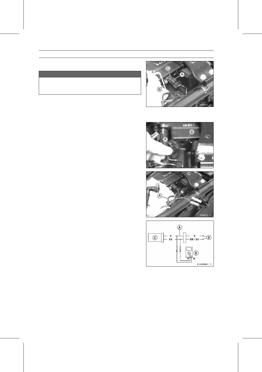
Remove the fuel tank (see Fuel Tank Removal).

Disconnect the intake air temperature sensor connector
[A].

Remove the intake air temperature sensor screw [B] and
pull out the intake air temperature sensor [C].

Put the intake air temperature sensor [A] into the air
cleaner housing [B].

Tighten:

Torque - Intake Air Temperature Sensor Screw: 1.2 N·m

(0.12 kgf·m, 11 in·lb)

Intake Air Temperature Sensor Output Voltage

Inspection

NOTE

Be sure the battery is fully charged.

Turn the ignition switch off.

Remove the fuel tank (see Fuel Tank Removal).

Disconnect the intake air temperature sensor connector
and connect the harness adapter [A] between these con-
nectors as shown.

Main Harness [B]
Intake Air Temperature Sensor [C]

Special Tool - Measuring Adapter: 57001-1700

Connect a digital meter [D] to the harness adapter leads.

Intake Air Temperature Sensor Output Voltage

Connections to Adapter:

Digital Meter (+)

R (sensor R) lead

Digital Meter (–)

BK (sensor BR/BK) lead

Measure the output voltage with the engine stopped and
the connector joined.

Turn the ignition switch on.

Output Voltage

Standard: About DC 2.25

2.50 V at intake air

temperature 20°C (68°F)

NOTE

The output voltage changes according to the intake air
temperature.

FUEL SYSTEM (DFI) 3-53

Intake Air Temperature Sensor (Service Code 13)

Turn the ignition switch off.
If the reading is within the standard, check the ECU for
its ground and power supply (see ECU Power Supply In-
spection).
If the ground and power supply are good, replace the ECU
(see ECU Removal/Installation).

If the reading is out of the standard, remove the ECU
and check the wiring for continuity between main harness
connectors.

Special Tool - Hand Tester: 57001-1394

Disconnect the ECU and sensor connectors.

Wiring Continuity Inspection

ECU Connector [A]

←→

Intake Air Temperature Sensor Connector [B]

R lead (ECU terminal 20) [C]
BR/BK lead (ECU terminal 22) [D]

If the wiring is good, check the intake air temperature sen-
sor resistance (see Intake Air Temperature Sensor Resis-
tance Inspection).

Intake Air Temperature Sensor Resistance

Inspection

Remove the intake air temperature sensor (see Intake Air
Temperature Sensor Removal/Installation).

Suspend the sensor [A] in a container of machine oil so
that the heat-sensitive portion is submerged.

Suspend a thermometer [B] with the heat-sensitive por-
tion [C] located in almost the same depth with the sensor.

NOTE

The sensor and thermometer must not touch the con-
tainer side or bottom.

Place the container over a source of heat and gradually
raise the temperature of the oil while stirring the oil gently
for even temperature.

Using a digital meter, measure the internal resistance
of the sensor across the terminals at the temperatures
shown in the following.

Intake Air Temperature Sensor Resistance

Standard: 5.4

6.6 k

at 0°C (32°F)

0.29

0.39 k

at 80°C (176°F)

If the reading is out of the standard, replace the sensor.
If the reading is within the standard, but the problem still
exists, replace the ECU (see ECU Removal/Installation).

3-54 FUEL SYSTEM (DFI)

Intake Air Temperature Sensor (Service Code 13)

Intake Air Temperature Sensor Circuit

1. ECU
2. Water-proof Joint 3
3. Intake Air Temperature Sensor

FUEL SYSTEM (DFI) 3-55

Water Temperature Sensor (Service Code 14)

Water Temperature Sensor Removal/Installation

NOTICE

Never drop the water temperature sensor especially
on a hard surface. Such a shock to the sensor can
damage it.

Drain the coolant (see Coolant Change in the Periodic
Maintenance chapter).

Disconnect the connector [A].

Remove the water temperature sensor [B].

Replace the gasket with a new one, and tighten the water
temperature sensor.

Torque - Water Temperature Sensor: 12 N·m (1.2 kgf·m, 106

in·lb)

Fill the engine with coolant and bleed the air from the cool-
ing system (see Coolant Change in the Periodic Mainte-
nance chapter).

Water Temperature Sensor Output Voltage

Inspection

NOTE

Be sure the battery is fully charged.

Turn the ignition switch off.

Disconnect the water temperature sensor connector and
connect the harness adapter [A] between these connec-
tors as shown.

Main Harness [B]
Water Temperature Sensor [C]

Special Tool - Measuring Adapter: 57001-1700

Connect a digital meter [D] to the harness adapter leads.

Water Temperature Sensor Output Voltage

Connections to Adapter:

Digital Meter (+)

R (sensor O) lead

Digital Meter (–)

BK (sensor BR/BK) lead

Measure the output voltage with the engine stopped and
with the connector joined.

Turn the ignition switch on.

Output Voltage

Standard: About DC 2.80

2.97 V at 20°C (68°F)

NOTE

The output voltage changes according to the coolant
temperature in the engine.

Turn the ignition switch off.
If the reading is within the standard, check the ECU for
its ground and power supply (see ECU Power Supply In-
spection).
If the ground and power supply are good, replace the ECU
(see ECU Removal/Installation).

3-56 FUEL SYSTEM (DFI)

Water Temperature Sensor (Service Code 14)

If the reading is out of the standard, remove the ECU
and check the wiring for continuity between main harness
connectors.

Special Tool - Hand Tester: 57001-1394

Disconnect the ECU and sensor connectors.

Wiring Continuity Inspection

ECU Connector [A]

←→

Water Temperature Sensor Connector [B]

O lead (ECU terminal 17) [C]
BR/BK lead (ECU terminal 22) [D]

If the wiring is good, check the water temperature sensor
resistance (see Water Temperature Sensor Resistance
Inspection).

Water Temperature Sensor Resistance Inspection

Refer to the Water Temperature Sensor Inspection in the
Electrical System chapter.
If the reading is within the standard, but the problem still
exists, replace the ECU (see ECU Removal/Installation).

Water Temperature Sensor Circuit

1. ECU
2. Water-proof Joint 3
3. Water Temperature Sensor

FUEL SYSTEM (DFI) 3-57

Crankshaft Sensor (Service Code 21)

The crankshaft sensor has no power source, and when

the engine stops, the crankshaft sensor generates no sig-
nals.

Crankshaft Sensor Removal/Installation

Refer to the Crankshaft Sensor Removal/Installation in
the Electrical System chapter.

Crankshaft Sensor Resistance Inspection

Refer to the Crankshaft Sensor Inspection in the Electrical
System chapter.
If the reading is within the standard, check the peak volt-
age (see Crankshaft Sensor Peak Voltage Inspection).

Crankshaft Sensor Peak Voltage Inspection

Refer to the Crankshaft Sensor Peak Voltage Inspection
in the Electrical System chapter.
If the reading is within the standard, remove the ECU and
check the wiring for continuity between main harness con-
nectors.

Special Tool - Hand Tester: 57001-1394

Disconnect the ECU and sensor connectors.

Wiring Continuity Inspection

ECU Connector [A]

←→

Crankshaft Sensor Connector [B]

Y lead (ECU terminal 11) [C]
Y/BK lead (ECU terminal 24) [D]

If the wiring is good, check the ECU for its ground and
power supply (see ECU Power Supply Inspection).
If the ground and power supply are good, replace the ECU
(see ECU Removal/Installation).

Crankshaft Sensor Circuit

1. ECU
2. Crankshaft Sensor

3-58 FUEL SYSTEM (DFI)

Speed Sensor (Service Code 24)

Speed Sensor Removal/Installation

Refer to the Speed Sensor Removal/Installation in the
Electrical System chapter.

Speed Sensor Inspection

Refer to the Speed Sensor Inspection in the Electrical
System chapter.

Speed Sensor Input Voltage Inspection

NOTE

Be sure the battery is fully charged.

Turn the ignition switch off.

Remove the fuel tank (see Fuel Tank Removal).

Disconnect the speed sensor connector and connect the
harness adapter [A] between speed sensor [B] and main
harness [C] connectors.

Connect a digital meter [D] to the harness adapter leads.

Special Tool - Throttle Sensor Setting Adapter #1: 57001

-1400

Speed Sensor Input Voltage

Connections to Adapter:

Digital Meter (+)

BL (sensor P) lead

Digital Meter (–)

BK/BL (sensor BK) lead

Measure the input voltage with the engine stopped and
with the connector joined.

Turn the ignition switch on.

Input Voltage

Standard: DC 4.75

5.25 V

Turn the ignition switch off.
If the reading is within the standard, check the output volt-
age (see Speed Sensor Output Voltage Inspection).

If the reading is out of the standard, remove the ECU
and check the wiring for continuity between main harness
connectors.

Special Tool - Hand Tester: 57001-1394

Disconnect the ECU and sensor connectors.

Wiring Continuity Inspection

ECU Connector [A]

←→

Speed Sensor Connector [B]

G lead (ECU terminal 8) [C]
BR/BK lead (ECU terminal 22) [D]

If the wiring is good, check the ECU for its ground and
power supply (see ECU Power Supply Inspection).
If the ground and power supply are good, replace the ECU
(see ECU Removal/Installation).

FUEL SYSTEM (DFI) 3-59

Speed Sensor (Service Code 24)

Speed Sensor Output Voltage Inspection

Raise the rear wheel off the ground with the stand.

Measure the output voltage at the speed sensor in the
same way as input voltage inspection.

Disconnect the speed sensor connector and connect the
harness adapter [A] between speed sensor [B] and main
harness [C] connectors.

Connect a digital meter [D] to the harness adapter leads.

Special Tool - Throttle Sensor Setting Adapter #1: 57001

-1400

Speed Sensor Output Voltage

Connections to Adapter:

Digital Meter (+)

Y/W (sensor Y) lead

Digital Meter (–)

BK/BL (sensor BK) lead

Measure the output voltage with the engine stopped and
with the connector joined.

Turn the ignition switch on.

Output Voltage

Standard: About DC 0.05

4 V at rear wheel turning

NOTE

Rotate the rear wheel by hand, confirm the output volt-
age will be raise or lower.

Turn the ignition switch off.
If the reading is out of the standard, replace the sensor.

If the reading is within the standard, remove the ECU and
check the wiring for continuity between main harness con-
nectors.

Special Tool - Hand Tester: 57001-1394

Disconnect the ECU and sensor connectors.

Wiring Continuity Inspection

ECU Connector [A]

←→

Speed Sensor Connector [B]

LG/R lead (ECU terminal 5) [C]
BR/BK lead (ECU terminal 22) [D]

If the wiring is good, check the ECU for its ground and
power supply (see ECU Power Supply Inspection).
If the ground and power supply are good, replace the ECU
(see ECU Removal/Installation).

3-60 FUEL SYSTEM (DFI)

Speed Sensor (Service Code 24)

Speed Sensor Circuit

1. ECU
2. Speed Sensor
3. Water-proof Joint 4
4. Water-proof Joint 3

FUEL SYSTEM (DFI) 3-61

Vehicle-down Sensor (Service Code 31)

Vehicle-down Sensor Removal/Installation

NOTICE

Never drop the vehicle-down sensor especially on
a hard surface. Such a shock to the sensor can
damage it.

Remove the fuel tank (see Fuel Tank Removal).

Disconnect the connector [A] and remove the vehi-
cle-down sensor [B] with damper.

Installation is the reverse of removal.

Apply grease to the vehicle-down sensor terminals.

The UP mark [A] of the sensor should face upward.

WARNING

Incorrect installation of the vehicle-down sensor
could cause sudden loss of engine power. The
rider could lose balance during certain riding situ-
ations for an accident resulting in injury or death.
Ensure that the vehicle-down sensor is held in
place by the sensor bracket.

Vehicle-down Sensor Inspection

NOTE

Be sure the battery is fully charged.

Connect a digital meter [A] to the connector [B] of the
vehicle-down sensor [C] with the needle adapter set [D].

Special Tool - Needle Adapter Set: 57001-1457

Vehicle-down Sensor Power Source Voltage

Connections to Sensor Connector:

Meter (+)

G lead [E]

Meter (–)

BR/BK lead [F]

Turn the ignition switch on, and measure the power
source voltage with the connector joined.

Input Voltage

Standard: DC 4.75

5.25 V

Turn the ignition switch off.
If the reading of input voltage is less than the standard,
check the ECU for its ground, power supply and wiring.
If the power source is normal, check the output voltage.

3-62 FUEL SYSTEM (DFI)

Vehicle-down Sensor (Service Code 31)

Remove the vehicle-down sensor (see Vehicle-down
Sensor Removal/Installation).

Do not disconnect the sensor connector.

Using the needle adapter set [A], connect a digital meter
[B] to the connector.

Special Tool - Needle Adapter Set: 57001-1457

Vehicle-down Sensor Output Voltage

Connections to Sensor Connector:

Meter (+)

Y/G lead [C]

Meter (–)

BR/BK lead [D]

Hold the sensor vertically.

Turn the ignition switch on, and measure the output volt-
age with the connector joined.

Tilt the sensor 60

70° or more [E] right or left, then hold

the sensor almost vertical with the arrow mark pointed up
[F], and measure the output voltage.

Output Voltage

Standard: with sensor tilted 60

70° or more right or

left: DC 0.65

1.35 V

with sensor arrow mark pointed up: DC
3.55

4.45 V

NOTE

If you need to test again, turn the ignition switch off, and
then on.

Turn the ignition switch off.
If the output voltage is normal, check the wiring.
If the wiring is good, check the ECU for its ground and
power supply (see ECU Power Supply Inspection).
If the ground and power supply are good, replace the ECU
(see ECU Removal/Installation).
If the output voltage is out of the specified, replace the
vehicle-down sensor.

FUEL SYSTEM (DFI) 3-63

Vehicle-down Sensor (Service Code 31)

Vehicle-down Sensor Circuit

1. ECU
2. Water-proof Joint 4
3. Vehicle-down Sensor
4. Water-proof Joint 3

3-64 FUEL SYSTEM (DFI)

Subthrottle Sensor (Service Code 32)

Subthrottle Sensor Removal/Adjustment

NOTICE

Do not remove or adjust the subthrottle sensor [A]
since it has been adjusted and set with precision at
the factory.
Never drop the throttle body assy especially on a
hard surface. Such a shock to the subthrottle sen-
sor can damage it.

Subthrottle Sensor Input Voltage Inspection

NOTE

Be sure the battery is fully charged.

Remove the right middle fairing (see Middle Fairing Re-
moval in the Frame chapter).

Turn the ignition switch off.

Disconnect the subthrottle sensor and connect the har-
ness adapter [A] between these connectors.

Special Tool - Throttle Sensor Setting Adapter:

57001

-1538

Connect a digital meter to the harness adapter leads.

Subthrottle Sensor Input Voltage

Connections to Adapter:

Digital Meter (+)

BK (sensor G) lead

Digital Meter (–)

W (sensor BR/BK) lead

Measure the input voltage with the engine stopped and
with the connector joined.

Turn the ignition switch on.

Input Voltage

Standard: DC 4.75

5.25 V

Turn the ignition switch off.
If the reading is within the standard, check the output volt-
age (see Subthrottle Sensor Output Voltage Inspection).

If the reading is out of the standard, remove the ECU
and check the wiring for continuity between main harness
connectors.

Special Tool - Hand Tester: 57001-1394

Disconnect the ECU and sensor connectors.

Wiring Continuity Inspection

ECU Connector [A]

←→

Subthrottle Sensor Connector [B]

G lead (ECU terminal 8) [C]
BR/BK lead (ECU terminal 22) [D]

If the wiring is good, check the ECU for its ground and
power supply (see ECU Power Supply Inspection).
If the ground and power supply are good, replace the ECU
(see ECU Removal/Installation).

FUEL SYSTEM (DFI) 3-65

Subthrottle Sensor (Service Code 32)

Subthrottle Sensor Output Voltage Inspection

Measure the output voltage at the subthrottle sensor in
the same way as input voltage inspection (see Subthrottle
Sensor Input Voltage Inspection).

Disconnect the subthrottle sensor connector and connect
the harness adapter [A] between these connectors.

Special Tool - Throttle Sensor Setting Adapter:

57001

-1538

Connect a digital meter to the harness adapter leads.

Subthrottle Sensor Output Voltage

Connections to Adapter:

Digital Meter (+)

R (sensor BL/W) lead

Digital Meter (–)

W (sensor BR/BK) lead

Remove the fuel tank (see Fuel Tank Removal).

Disconnect the subthrottle valve actuator harness con-
nector [A].

Turn the ignition switch on.

Measure the output voltage when the subthrottle valve is
completely closed by turning the lever [A] fully clockwise
[B].

Output Voltage

Standard: DC 0.78

0.82 V at subthrottle valve full

close position
DC 3.9

4.5 V at subthrottle valve full open

position (for reference)

NOTE

Turn the lever counterclockwise, confirm the output volt-
age will be raise.

The standard voltage refers to the value when the volt-
age reading at the Input Voltage Inspection shows 5 V
exactly.

When the input voltage reading shows other than 5 V,
derive a voltage range as follows.
Example:
In the case of a input voltage of 4.75 V.
0.78 × 4.75 ÷ 5.00 = 0.741 V
0.82 × 4.75 ÷ 5.00 = 0.779 V
Thus, the valid range is 0.741

0.779 V

Turn the ignition switch off.
If the reading is out of the standard, check the subthrot-
tle sensor resistance (see Subthrottle Sensor Resistance
Inspection).

3-66 FUEL SYSTEM (DFI)

Subthrottle Sensor (Service Code 32)

If the reading is within the standard, remove the ECU and
check the wiring for continuity between main harness con-
nectors.

Special Tool - Hand Tester: 57001-1394

Disconnect the ECU and sensor connectors.

Wiring Continuity Inspection

ECU Connector [A]

←→

Subthrottle Sensor Connector [B]

BL/W lead (ECU terminal 19) [C]
BR/BK lead (ECU terminal 22) [D]

If the wiring is good, check the ECU for its ground and
power supply (see ECU Power Supply Inspection).
If the ground and power supply are good, replace the ECU
(see ECU Removal/Installation).

Subthrottle Sensor Resistance Inspection

Turn the ignition switch off.

Disconnect the subthrottle sensor connector.

Connect a digital meter [A] to the subthrottle sensor con-
nector [B].

Measure the subthrottle sensor resistance.

Subthrottle Sensor Resistance

Connections: G lead [C]

←→

BR/BK lead [D]

Standard:

4

6 k

If the reading is out of the standard, replace the throttle
body assy (see Throttle Body Assy Removal/Installation).
If the reading is within the standard, but the problem still
exists, replace the ECU (see ECU Removal/Installation).

Subthrottle Sensor Circuit

1. ECU
2. Subthrottle Sensor
3. Water-proof Joint 4
4. Water-proof Joint 3

FUEL SYSTEM (DFI) 3-67

Oxygen Sensor - not activated (Service Code 33) (Equipped Models)

Oxygen Sensor Removal/Installation

Refer to the Oxygen Sensor Removal/Installation in the
Electrical System chapter.

Oxygen Sensor Inspection

Remove the left middle fairing (see Middle Fairing Re-
moval in the Frame chapter).

Warm up the engine thoroughly until the radiator fan
starts.

Turn the ignition switch off.

Disconnect the oxygen sensor lead connector and con-
nect the harness adapter [A] between these connectors.

Special Tool - Oxygen Sensor Measuring Adapter: 57001

-1682

Connect a digital meter to the harness adapter leads.

Oxygen Sensor Output Voltage

Connections to Adapter:

Digital Meter (+)

BL (sensor BL) lead

Digital Meter (

)

BR (sensor W) lead

Disconnect the hose [A] from the air suction valve cover.

Do not disconnect the air switching valve connector.

Install the suitable plug [A] on the fitting of the air suction
valve cover to shut off the secondary air.

Start the engine and let it idle.

Measure the output voltage with the connector joined.

Output Voltage (with Plug)

Standard: DC 0.7 V or more

Next, remove the plug from the fitting [A] with idling.

Measure the output voltage with the connector joined.

Output Voltage (without Plug)

Standard: DC 0.2 V or less

Turn the ignition switch off.

3-68 FUEL SYSTEM (DFI)

Oxygen Sensor - not activated (Service Code 33) (Equipped Models)

If the reading is out of the standard (with plug: DC 0.7 V
or more, without plug: DC 0.2 V or less), remove the ECU
and check the wiring for continuity between main harness
connectors.

Special Tool - Hand Tester: 57001-1394

Disconnect the ECU and sensor connectors.

Wiring Continuity Inspection

ECU Connector [A]

←→

Oxygen Sensor Connector [B]

BL/Y lead (ECU terminal 4) [C]
BR/BK lead (ECU terminal 22) [D]

If the wiring is good, replace the sensor.
If the reading is within the standard (with plug: DC 0.7 V
or more, without plugs: DC 0.2 V or less), check the ECU
for its ground and power supply (see ECU Power Supply
Inspection).
If the ground and power supply are good, replace the ECU
(see ECU Removal/Installation).

FUEL SYSTEM (DFI) 3-69

Oxygen Sensor - not activated (Service Code 33) (Equipped Models)

Oxygen Sensor Circuit

1. Oxygen Sensor
2. ECU
3. Water-proof Joint 1
4. Frame Ground
5. Engine Ground
6. Battery 12 V 8 Ah
7. Main Fuse 30 A
8. Starter Relay
9. Fuse Box 1

10. FI Fuse 15A

11. Ignition Fuse 10 A

12. Relay Box
13. ECU Main Relay
14. Water-proof Joint 6
15. Ignition Switch
16. Water-proof Joint 3

3-70 FUEL SYSTEM (DFI)

Stick Coils #1, #2 (Service Code 51, 52)

Stick Coil #1: Service Code 51
Stick Coil #2: Service Code 52

Stick Coil Removal/Installation

Refer to the Stick Coil Removal/Installation in the Electri-
cal System chapter.

Stick Coil Primary Winding Resistance Inspection

Refer to the Stick Coil Inspection in the Electrical System
chapter.
If the reading is within the standard, check the input volt-
age (see Stick Coil Input Voltage Inspection).

Stick Coil Input Voltage Inspection

NOTE

Be sure the battery is fully charged.

Turn the ignition switch off.

Remove the ECU (see ECU Removal).

Do not disconnect the ECU connectors.

Connect a digital meter [A] to the connector [B] with the
needle adapter set.

Special Tool - Needle Adapter Set: 57001-1457

Stick Coil Input Voltage

Connections to ECU Connector:

For Stick Coil #1

Digital Meter (+)

BK lead (terminal 35)

Digital Meter (–)

BK/Y lead (terminal 43)

For Stick Coil #2

Digital Meter (+)

BK/O lead (terminal 44)

Digital Meter (–)

BK/Y lead (terminal 43)

Measure the input voltage to each primary winding of the
stick coils with the engine stopped and with the connec-
tors joined.

Turn the engine stop switch to run position.

Turn the ignition switch on.

Input Voltage

Standard: Battery Voltage

Turn the ignition switch off.
If the input voltage is out of the standard, check the wiring
for continuity (see wiring diagram in this section).
If the wiring is good, check the ECU for its ground and
power supply (see ECU Power Supply Inspection).
If the ground and power supply are good, replace the ECU
(see ECU Removal/Installation).
If the input voltage is within the standard, check the ECU
for its ground and power supply (see ECU Power Supply
Inspection).
If the ground and power supply are good, replace the ECU
(see ECU Removal/Installation).

FUEL SYSTEM (DFI) 3-71

Stick Coils #1, #2 (Service Code 51, 52)

Stick Coil Circuit

1. ECU
2. Water-proof Joint 2
3. Frame Ground
4. Engine Ground
5. Battery 12 V 8 Ah
6. Main Fuse 30 A
7. Starter Relay
8. Fuse Box 1
9. Ignition Fuse 10 A

10. Water-proof Joint 7

11. Ignition Switch

12. Engine Stop Switch
13. Stick Coils
14. Water-proof Joint 5

3-72 FUEL SYSTEM (DFI)

Radiator Fan Relay (Service Code 56)

Radiator Fan Relay Removal/Installation

The radiator fan relay is built in the relay box [A].

Refer to the Relay Box Removal in the Electrical System
chapter.

Radiator Fan Relay Inspection

Refer to the Relay Circuit Inspection in the Electrical Sys-
tem chapter.
If the radiator fan relay is normal, check the wiring for
continuity (see wiring diagram in this section).
If the wiring is good, check the ECU for its ground and
power supply (see ECU Power Supply Inspection).
If the ground and power supply are good, replace the ECU
(see ECU Removal/Installation).

FUEL SYSTEM (DFI) 3-73

Radiator Fan Relay (Service Code 56)

Radiator Fan Relay Circuit

1. ECU
2. Water-proof Joint 2
3. Frame Ground
4. Engine Ground
5. Battery 12 V 8 Ah
6. Main Fuse 30 A
7. Starter Relay
8. Fuse Box 1
9. Fan Fuse 10 A

10. Ignition Fuse 10 A

11. Relay Box

12. Radiator Fan Relay
13. Water-proof Joint 7
14. Ignition Switch
15. Fan Motor

3-74 FUEL SYSTEM (DFI)

Subthrottle Valve Actuator (Service Code 62)

Subthrottle Valve Actuator Removal

NOTICE

Do not remove the subthrottle valve actuator [A]
since it has been adjusted and set with precision
at the factory.
Never drop the throttle body assy especially on a
hard surface. Such a shock to the subthrottle valve
actuator can damage it.

Subthrottle Valve Actuator Inspection

NOTE

Be sure the battery is fully charged.

Remove the left middle fairing (see Middle Fairing Re-
moval in the Frame chapter).

Turn the ignition switch on.

Check to see that the subthrottle valves lever [A] open
and close smoothly.

Turn the ignition switch off.
If the subthrottle valves do not operate, check the sub-
throttle valve actuator resistance (see Subthrottle Valve
Actuator Resistance Inspection).

Subthrottle Valve Actuator Resistance Inspection

Turn the ignition switch off.

Remove the fuel tank (see Fuel Tank Removal).

Disconnect the subthrottle valve actuator connector [A].

Connect a digital meter to the subthrottle valve actuator
connector [A].

Measure the subthrottle valve actuator resistance.

Subthrottle Valve Actuator Resistance

Connections: BK lead [1]

←→

P lead [2]

G lead [3]

←→

W/BL lead [4]

Standard:

About 5.2

7.8

If the reading is out of the standard, replace the throttle
body assy (see Throttle Body Assy Removal/Installation).
If the reading is within the standard, check the input volt-
age (see Subthrottle Valve Actuator Input Voltage Inspec-
tion).

FUEL SYSTEM (DFI) 3-75

Subthrottle Valve Actuator (Service Code 62)

Subthrottle Valve Actuator Input Voltage

Inspection

NOTE

Be sure the battery is fully charged.

Remove the fuel tank (see Fuel Tank Removal).

Turn the ignition switch off.

Disconnect the subthrottle valve actuator connector and
connect the harness adapter [A] between these connec-
tors as shown.

Main Harness [B]
Subthrottle Valve Actuator [C]

Special Tool - Measuring Adapter: 57001-1700

Connect the peak voltage adapter [D] and a digital meter
[E] to the harness adapter leads.

Special Tool - Peak Voltage Adapter: 57001-1415

Type: KEK-54-9-B

Subthrottle Valve Actuator Input Voltage

Connections to Adapter:

(I) Digital Meter (+)

R (actuator P) lead

Digital Meter (–)

BK (actuator BK) lead

(II) Digital Meter (+)

W (actuator W/BL) lead

Digital Meter (–)

Y (actuator G) lead

Measure the actuator input voltage with the engine
stopped and with the connector joined.

Turn the ignition switch on.

Input Voltage

Standard: About DC 11.5

13.5 V

Turn the ignition switch off.
If the reading is in specification, but the actuator does not
operate, replace the throttle body assy (see Throttle Body
Assy Removal/Installation).

If the reading is out of the specification, remove the ECU
and check the wiring for continuity between main harness
connectors.

Special Tool - Hand Tester: 57001-1394

Disconnect the ECU and actuator connectors.

Wiring Continuity Inspection

ECU Connector [A]

←→

Subthrottle Valve Actuator Connector [B]

W/BL lead (ECU terminal 1) [C]
BK/O lead (ECU terminal 2) [D]
G/Y lead (ECU terminal 14) [E]
P lead (ECU terminal 15) [F]

If the wiring is good, check the ECU for its ground and
power supply (see ECU Power Supply Inspection).
If the ground and power supply are good, replace the ECU
(see ECU Removal/Installation).

3-76 FUEL SYSTEM (DFI)

Subthrottle Valve Actuator (Service Code 62)

Subthrottle Valve Actuator Circuit

1. ECU
2. Subthrottle Valve Actuator

FUEL SYSTEM (DFI) 3-77

Air Switching Valve (Service Code 64)

Air Switching Valve Removal/Installation

Refer to the Air Switching Valve Removal/Installation in
the Engine Top End chapter.

Air Switching Valve Inspection

Refer to the Air Switching Valve Unit Test in the Electrical
System chapter.
If the air switching valve is normal, check the wiring for
continuity (see wiring diagram in this section).
If the wiring is good, check the ECU for its ground and
power supply (see ECU Power Supply Inspection).
If the ground and power supply are good, replace the ECU
(see ECU Removal/Installation).

Air Switching Valve Circuit

1. ECU
2. Water-proof Joint 1
3. Water-proof Joint 2
4. Frame Ground
5. Engine Ground
6. Battery 12 V 8 Ah
7. Main Fuse 30 A
8. Starter Relay

9. Fuse Box 1

10. FI Fuse 15 A

11. Ignition Fuse 10 A

12. Relay Box
13. ECU Main Relay
14. Water-proof Joint 6
15. Ignition Switch
16. Air Switching Valve

3-78 FUEL SYSTEM (DFI)

Oxygen Sensor Heater (Service Code 67) (Equipped Models)

Oxygen Sensor Heater Removal/Installation

The oxygen sensor heater is built in the oxygen sensor.

So, the heater itself can not be removed. Remove the oxy-
gen sensor (see Oxygen Sensor Removal in the Electrical
System chapter).

Oxygen Sensor Heater Resistance Inspection

Turn the ignition switch off.

Remove the left middle fairing (see Middle Fairing Re-
moval in the Frame chapter).

Disconnect the oxygen sensor lead connector [A].

Connect a digital meter [A] to the oxygen sensor lead con-
nector [B].

Measure the oxygen sensor heater resistance.

Oxygen Sensor Heater Resistance

Connections: BK lead [C]

←→

BK lead [D]

Standard: 11.7

14.5

at 20°C (68°F)

If the reading is out of the standard, replace the sensor.
If the reading is within the standard, check the power
source voltage (see Oxygen Sensor Heater Power
Source Voltage Inspection).

Oxygen Sensor Heater Power Source Voltage

Inspection

NOTE

Be sure the battery is fully charged.

Turn the ignition switch off.

Disconnect the oxygen sensor lead connector and con-
nect the harness adapter [A] between these connectors.

Special Tool - Oxygen Sensor Measuring Adapter: 57001

-1682

Connect a digital meter to the harness adapter lead.

Oxygen Sensor Power Source Voltage

Connections to Adapter:

Digital Meter (+)

P (sensor BK) lead

Digital Meter (–)

Battery (–) terminal

Measure the power source voltage with the engine
stopped and with the connector joined.

Turn the ignition switch on.

Power Source Voltage

Standard: Battery Voltage

Turn the ignition switch off.
If the reading is in specification, but the problem still ex-
ists, replace the ECU (see ECU Removal/Installation).
If the reading is out of the standard, check the following.

FI fuse 15 A and ignition fuse 10 A (see Fuse Inspection
in the Electrical System chapter)
Power Source Wiring (see wiring diagram in this section)

FUEL SYSTEM (DFI) 3-79

Oxygen Sensor Heater (Service Code 67) (Equipped Models)

If the fuse and wiring are good, remove the ECU and
check the wiring for continuity between main harness con-
nectors.

Special Tool - Hand Tester: 57001-1394

Disconnect the ECU and sensor connectors.

Wiring Continuity Inspection

ECU Connector [A]

←→

Oxygen Sensor Connector [B]

P/BK lead (ECU terminal 23) [C]

If the wiring is good, check the ECU for its ground and
power supply (see ECU Power Supply Inspection).
If the ground and power supply are good, replace the ECU
(see ECU Removal/Installation).

Oxygen Sensor Circuit

1. Oxygen Sensor
2. ECU
3. Water-proof Joint 1
4. Frame Ground
5. Engine Ground
6. Battery 12 V 8 Ah
7. Main Fuse 30 A
8. Starter Relay
9. Fuse Box 1

10. FI Fuse 15A

11. Ignition Fuse 10 A

12. Relay Box
13. ECU Main Relay
14. Water-proof Joint 6
15. Ignition Switch
16. Water-proof Joint 3

3-80 FUEL SYSTEM (DFI)

Oxygen Sensor - Incorrect Output Voltage (Service Code 94) (Equipped Models)

Oxygen Sensor Removal/Installation

Refer to the Oxygen Sensor Removal/Installation in the
Electrical System chapter.

Oxygen Sensor Inspection

Remove the left middle fairing (see Middle Fairing Re-
moval in the Frame chapter).

Warm up the engine thoroughly until the radiator fan
starts.

Turn the ignition switch off.

Disconnect the oxygen sensor lead connector and con-
nect the harness adapter [A] between these connectors.

Special Tool - Oxygen Sensor Measuring Adapter: 57001

-1682

Connect a digital meter to the harness adapter leads.

Oxygen Sensor Output Voltage

Connections to Adapter:

Digital Meter (+)

BL (sensor BL) lead

Digital Meter (

)

BR (sensor W) lead

Disconnect the hose [A] from the air suction valve cover.

Do not disconnect the air switching valve connector.

Install the suitable plug [A] on the fitting of the air suction
valve cover to shut off the secondary air.

Start the engine and let it idle.

Measure the output voltage with the connector joined.

Output Voltage (with Plug)

Standard: DC 0.7 V or more

FUEL SYSTEM (DFI) 3-81

Oxygen Sensor - Incorrect Output Voltage (Service Code 94) (Equipped Models)

Next, remove the plug from the fitting [A] with idling.

Measure the output voltage with the connector joined.

Output Voltage (without Plug)

Standard: DC 0.2 V or less

Turn the ignition switch off.
If the reading is out of the standard (with plug: DC 0.7 V or
more, without plug: DC 0.2 V or less), check the following.

Fuel Pressure (see Fuel Pressure Inspection)
Fuel Injector (see Fuel Injectors section)

If the fuel pressure and fuel injectors are good, replace
the sensor.
If the reading is within the standard (with plug: DC 0.7 V
or more, without plug: DC 0.2 V or less), check the ECU
for its ground and power supply (see ECU Power Supply
Inspection).
If the ground and power supply are good, replace the ECU
(see ECU Removal/Installation).

Oxygen Sensor Circuit

1. Oxygen Sensor
2. ECU
3. Water-proof Joint 1
4. Frame Ground
5. Engine Ground
6. Battery 12 V 8 Ah
7. Main Fuse 30 A
8. Starter Relay
9. Fuse Box 1

10. FI Fuse 15A

11. Ignition Fuse 10 A

12. Relay Box
13. ECU Main Relay
14. Water-proof Joint 6
15. Ignition Switch
16. Water-proof Joint 3

3-82 FUEL SYSTEM (DFI)

Purge Valve (Service Code 3A) (CAL Model)

Purge Valve Removal/Installation

Remove the left middle fairing (see Middle Fairing Re-
moval in the Frame chapter).

Disconnect the purge valve connector [A] and tubes [B].

Remove the purge valve mounting nut [C] and purge valve
[D].

Installation is the reverse of removal.

Tighten:

Torque - Purge Valve Mounting Nut: 9.8 N·m (1.0 kgf·m, 87

in·lb)

Run the tubes correctly (see Cable, Wire, and Hose Rout-
ing section in the Appendix chapter).

Purge Valve Inspection

Remove the purge valve (see Purge Valve Removal/In-
stallation).

Set the hand tester [A] to the × 1

range and connect it

to the purge valve terminals as shown in the figure.

Special Tool - Hand Tester: 57001-1394

Purge Valve Resistance

Standard: 30

34

at 20°C (68°F)

If the resistance reading is out of the specified value, re-
place it with a new one.

Connect the 12 V battery [A] to the purge valve terminals
as shown.

Blow the air to the intake air duct [A], and make sure that
the air flows from the outlet air duct [B].

FUEL SYSTEM (DFI) 3-83

Purge Valve (Service Code 3A) (CAL Model)

Disconnect the 12 V battery.

Blow the air to the intake air duct [A] again, and make sure
that the air does not flow from the outlet air duct [B].
If the purge valve dose not operate as described, replace
it with a new one.

Purge Valve Circuit

1. Ignition Switch
2. Purge Valve
3. ECU
4. Water-proof Joint 1
5. Water-proof Joint 2
6. Frame Ground
7. Engine Ground
8. Battery 12 V 8 Ah

9. Main Fuse 30 A

10. Starter Relay

11. Relay Box

12. ECU Main Relay
13. Fuse Box 1
14. FI Fuse 15 A
15. Ignition Fuse 10 A
16. Water-proof Joint 6


Content      ..     3      4      5      6     ..