Kawasaki Ninja 250R Motorcycle. Service Manual (2007) - page 3
CRANKSHAFT/TRANSMISSION 9-7
Specifications
Item
Standard
Service Limit
None
31.009 ∼ 31.016 mm
- - -
(1.2208 ∼ 1.2211 in.)
Crankshaft Main Bearing Insert Thickness:
Black
1.495 ∼ 1.499 mm
- - -
(0.0589 ∼ 0.0590 in.)
Blue
1.499 ∼ 1.503 mm
- - -
(0.0590 ∼ 0.0592 in.)
Yellow
1.503 ∼ 1.507 mm
- - -
(0.0592 ∼ 0.0593 in.)
Crankshaft Side Clearance
0.05 ∼ 0.20 mm
0.40 mm
(0.002 ∼ 0.008 in.)
(0.016 in.)
Balancer
Balancer Shaft Bearing Insert/Journal
0.020 ∼ 0.044 mm
0.07 mm
Clearance
(0.0008 ∼ 0.0017 in.)
(0.0028 in.)
Balancer Shaft Journal Diameter:
25.984 ∼ 26.000 mm
25.96 mm
(1.0230 ∼ 1.0236 in.)
(1.022 in.)
Marking
None
25.984 ∼ 25.994 mm
- - -
(1.0230 ∼ 1.0234 in.)
○
25.995 ∼ 26.000 mm
- - -
(1.0234 ∼ 1.0236 in.)
Crankcase Balancer Shaft Bore Diameter:
29.000 ∼ 29.016 mm
- - -
(1.1417 ∼ 1.1424 in.)
Marking
○
29.000 ∼ 29.008 mm
- - -
(1.1417 ∼ 1.1420 in.)
None
29.009 ∼ 29.016 mm
- - -
(1.1421 ∼ 1.1424 in.)
Balancer Shaft Bearing Insert Thickness:
Brown
1.495 ∼ 1.499 mm
- - -
(0.0589 ∼ 0.0590 in.)
Black
1.499 ∼ 1.503 mm
- - -
(0.0590 ∼ 0.0592 in.)
Blue
1.503 ∼ 1.507 mm
- - -
(0.0592 ∼ 0.0593 in.)
Transmission
Gear Backlash
0 ∼ 0.17 mm
0.25 mm
(0 ∼ 0.0067 in.)
(0.010 in.)
Gear Shift Fork Groove Width
5.05 ∼ 5.15 mm
5.3 mm
(0.1988 ∼ 0.2028 in.)
(0.209 in.)
Shift Fork Ear Thickness
4.9 ∼ 5.0 mm
4.8 mm
(0.1929 ∼ 0.1969 in.)
(0.189 in.)
Shift Fork Guide Pin Diameter
5.9 ∼ 6.0 mm
5.8 mm
(0.2323 ∼ 0.2362 in.)
(0.228 in.)
Shift Drum Groove Width
6.05 ∼ 6.20 mm
6.3 mm
(0.2382 ∼ 0.2441 in.)
(0.248 in.)
*: Journal clearance less than 0.025 mm (0.0010 in.) can not be measured by plastigage, however,
using genuine parts maintains the minimum standard clearance.
9-8 CRANKSHAFT/TRANSMISSION
Specifications
Connecting Rod Big End Bearing Insert Selection
Con-rod Big End Bore
Crankpin Diameter
Bearing Insert
Diameter Marking
Marking
Size Color
Parts Number
○
○
Black
92028-1493
None
None
○
None
Blue
92028-1492
None
○
Brown
92028-1494
Crankshaft Main Bearing Insert Selection
Crankcase Main
Crankpin Main
Bearing Insert**
Bearing Bore
Journal Diameter
Size Color
Parts Number
Journal Nos.
Diameter Marking
Marking
92028-1487
1, 3
○
1
Black
92028-1490
2
92028-1582
1, 3
None
None
Yellow
92028-1586
2
○
None
92028-1486
1, 3
Blue
None
1
92028-1489
2
**: The bearing inserts for No.2 journal have an oil groove.
Balancer Shaft Bearing Insert Selection
Balancer Shaft
Crankcase Balancer
Bearing Insert
Journal Diameter
Shaft Bore Diameter
Size Color
Parts Number
Marking
Marking
○
○
Brown
92028-1424
○
None
Black
92028-1423
None
○
None
None
Blue
92028-1422
CRANKSHAFT/TRANSMISSION 9-9
Special Tools and Sealants
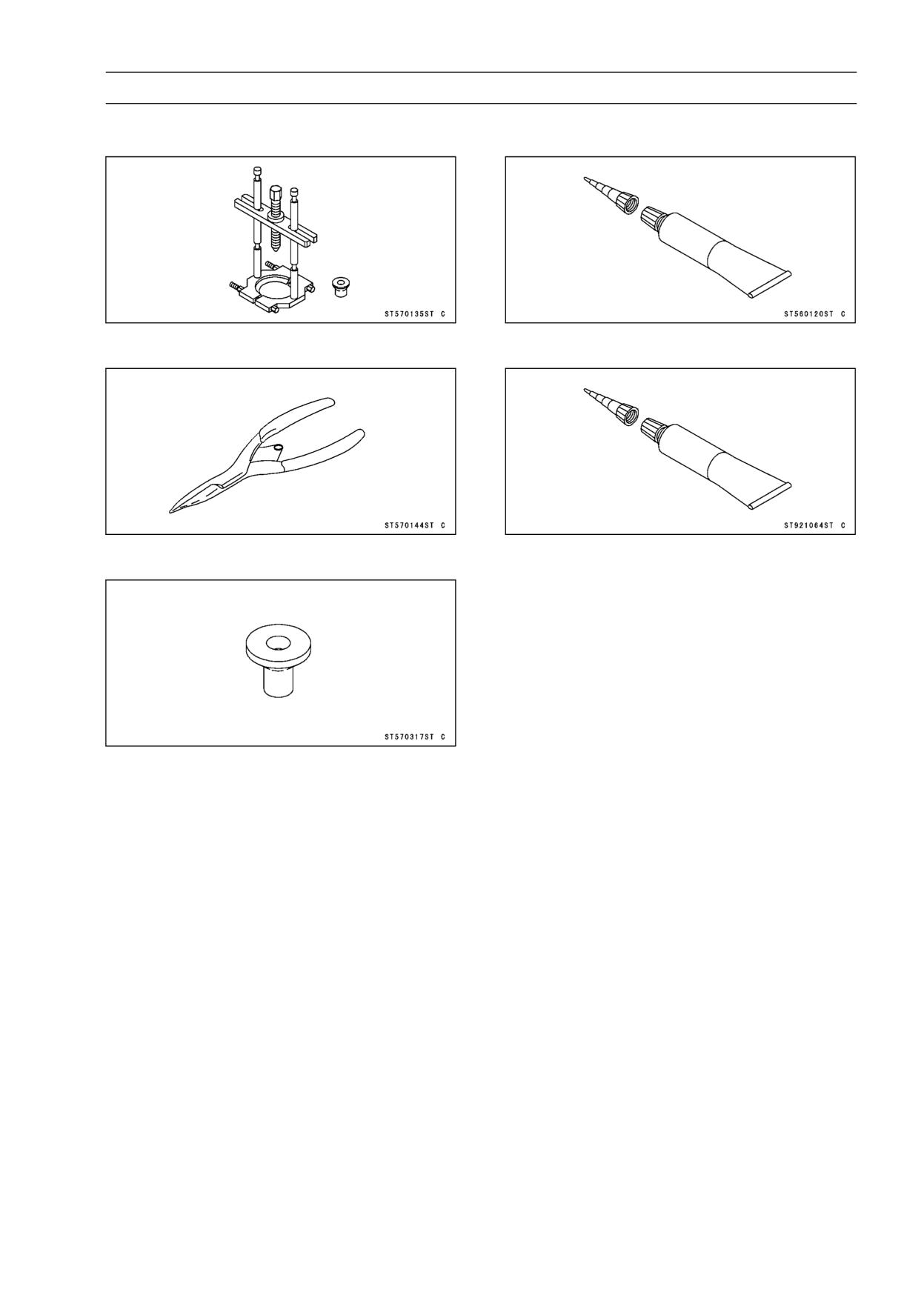
Bearing Puller:
Liquid Gasket, TB1211:
57001-135
56019-120
Outside Circlip Pliers:
Liquid Gasket, TB1216B:
57001-144
92104-1064
Bearing Puller Adapter:
57001-317
9-10 CRANKSHAFT/TRANSMISSION
Crankcase
Crankcase Splitting
• Remove the engine (see Engine Removal in the Engine
Removal/Installation chapter).
• Set the engine on a clean surface or, preferably mount it
on an engine stand to hold the engine steady while parts
are being removed.
• Remove the water pipe and hose (cylinder rearward).
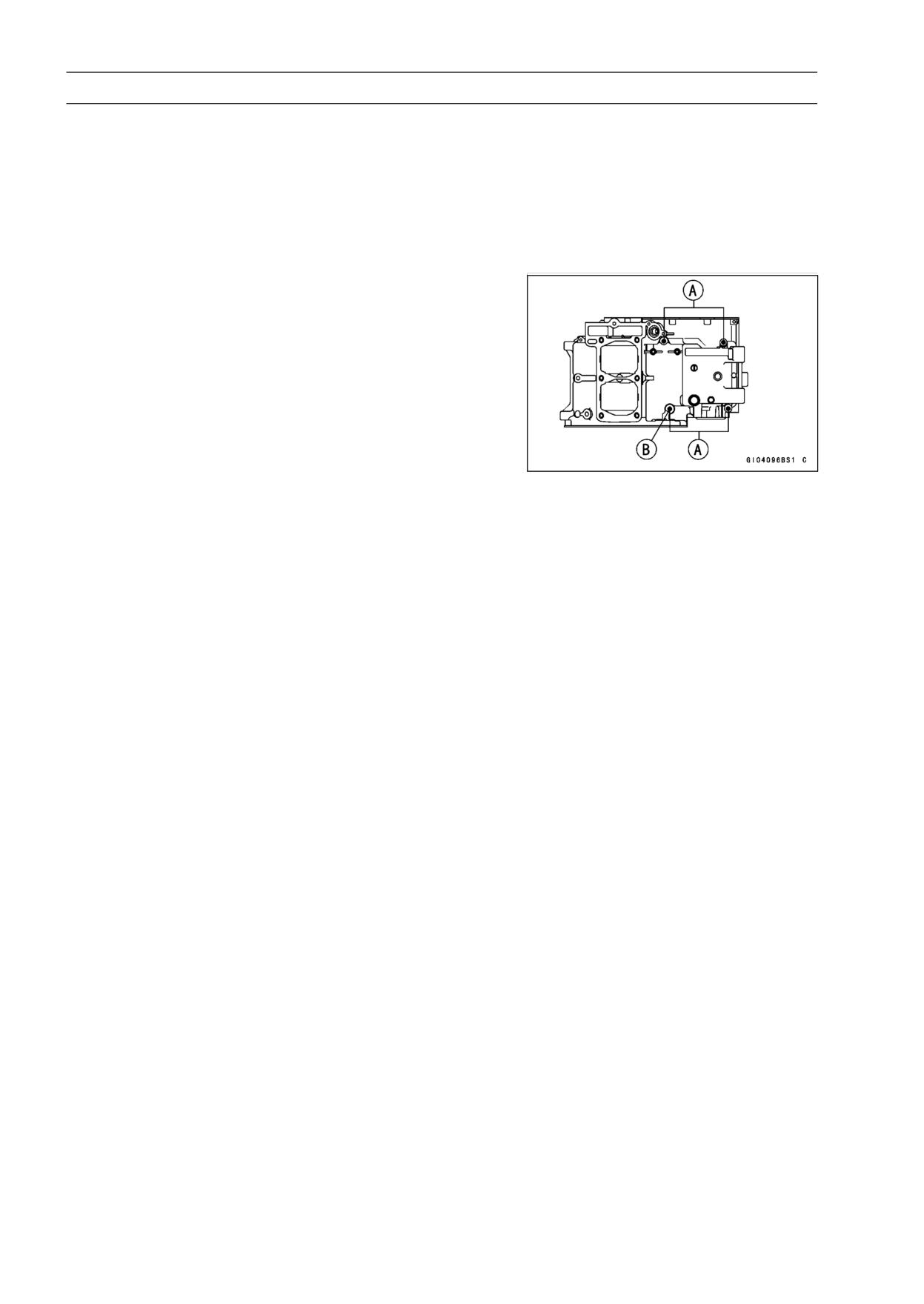
NOTE
○If the engine is to be mounted on an engine stand, the
upper crankcase half bolts [A] shown must be removed
before mounting the engine.
Washer [B]
• Remove:
Alternator Cover (see Alternator Cover Removal in the
Electrical System chapter)
Water Pump, Hose and Pipe (see Water Pump Removal
in the Cooling System chapter)
Starter Motor Clutch Gear
Oil Pipe and Banjo Bolt
Starter Motor (see Starter Motor Removal in the Electri-
cal System chapter)
Oil Pump (see Oil Pump Removal in the Engine Lubri-
cation System chapter)
Cylinder Head Cover (see Cylinder Head Cover Re-
moval in the Engine Top End chapter)
Alternator Rotor (see Alternator Rotor Removal in the
Electrical System chapter)
One Way Clutch Gear
Oil Hose Banjo Bolt
Camshafts Chain Tensioner (see Camshafts Chain Ten-
sioner Removal in the Engine Top End chapter)
Clutch Cover (see Clutch Cover Removal in the Clutch
chapter)
Camshafts (see Camshaft Removal in the Engine Top
End chapter)
Cylinder Head (see Cylinder Head Removal in the En-
gine Top End chapter)
Cylinder (see Cylinder Removal in the Engine Top End
chapter)
Pistons (see Piston Removal in the Engine Top End
chapter)
CRANKSHAFT/TRANSMISSION 9-11
Crankcase
• Remove the clutch only if the transmission drive shaft as-
sembly is to be removed.
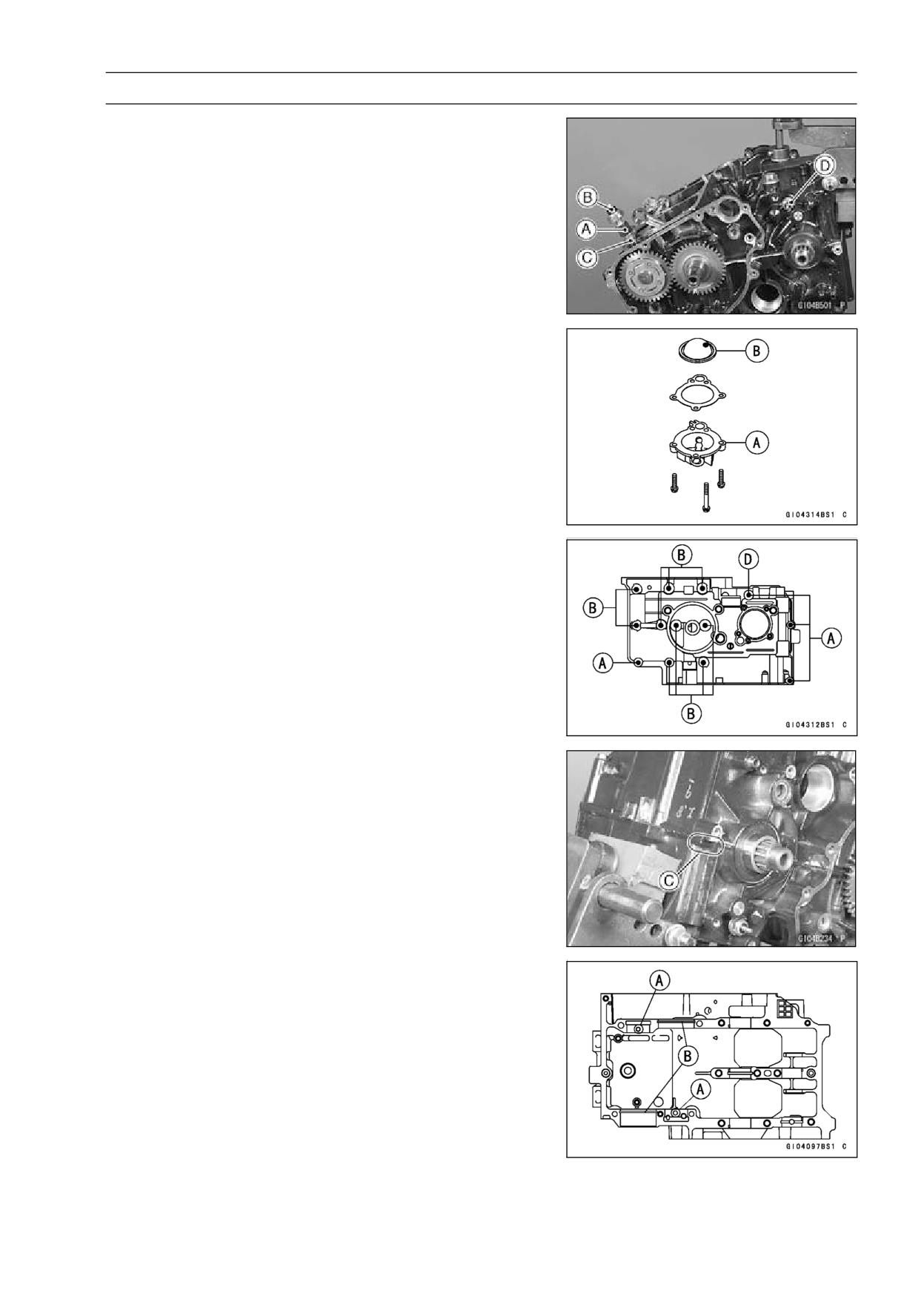
• Remove the oil pressure bolt [A] with the oil pressure
switch [B] and oil hose [C].
• Remove the neutral switch [D].
• Remove the upper crankcase half bolt (1) (3 were re-
moved just after engine removal).
• Turn the engine upside down.
• Remove the oil filter mounting bolt, oil filter, and large
O-ring.
• Remove the oil screen cover [A] and screen [B].
• Remove the 6 mm [A] and 8 mm [B] lower crankcase half
bolt, ply the point [C] shown to split the two crankcase
halves apart, and lift off the lower crankcase half.
Washer [D]
Crankcase Assembly
NOTE
○The upper/lower crankcase halves are machined at the
factory as an assembly, so the crankcase halves must
be replaced as a set.
• Assembly is the reverse of splitting. Be careful of the
following items.
○With a high flash-point solvent, clean off the mating sur-
face of the crankcase halves and wipe dry.
○When installing the output and drive shafts, the crankcase
set pins [A] must go into the holes in the needle bearing
outer races, and the set rings [B] must fit into the grooves
in the ball bearings.
9-12 CRANKSHAFT/TRANSMISSION
Crankcase
○When the oil pressure switch is installed, apply the liquid
gasket to the threads of the switch.
Sealant - Liquid Gasket, TB1211: 56019-120
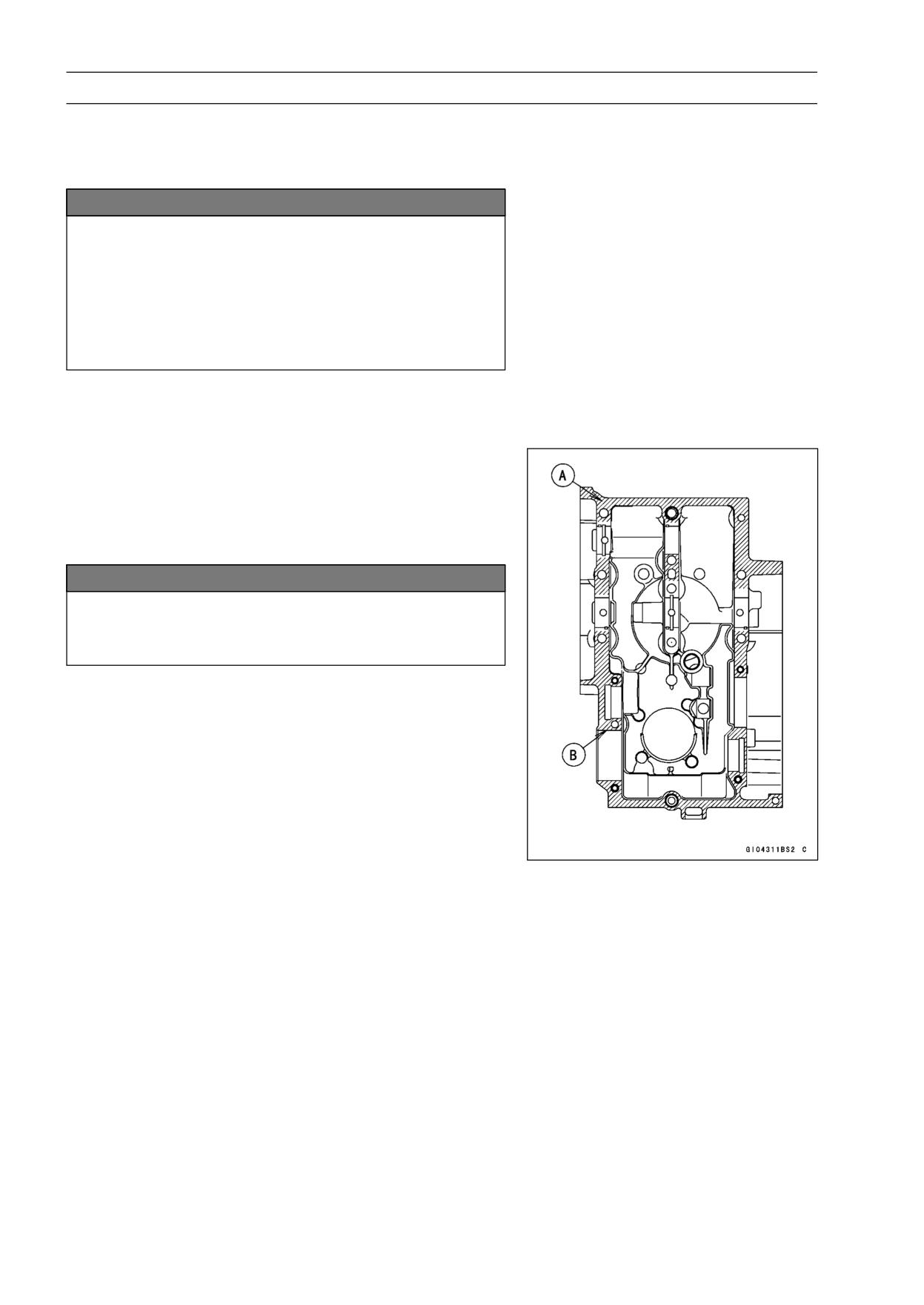
NOTICE
Make sure the crankcase set pins are properly
aligned to avoid damage to the crankcases upon
installation.
Don’t use usual set pins because the set pins of
this model are different from usual pins. They are
hollow and also used to pass oil. If you use usual
pins by mistake, the engine always seized.
○Check that the knock pins (2) are in place.
○Apply a little engine oil to the transmission gears ball bear-
ings, shift drum, and crankshaft main bearing inserts.
• Apply liquid gasket to the mating surface of the lower
crankcase half.
Sealant - Liquid Gasket, TB1216B: 92104-1064 [A]
○After assembling the crankcase halves, wipe off excess
liquid gasket on the inside portion [B].
NOTICE
If liquid gasket adheres to any areas not indicated,
the engine oil passage may be obstructed, causing
engine seizure.
○Check to see that the shift drum is in the neutral position,
that is, the projection at operating plate is seen from neu-
tral switch hole at the upper crankcase half.
○When fitting the lower crankcase half on the upper
crankcase half, each shift fork must fit in its gear groove.
○Loosely tighten all lower crankcase half bolts to a snug fit.
CRANKSHAFT/TRANSMISSION 9-13
Crankcase
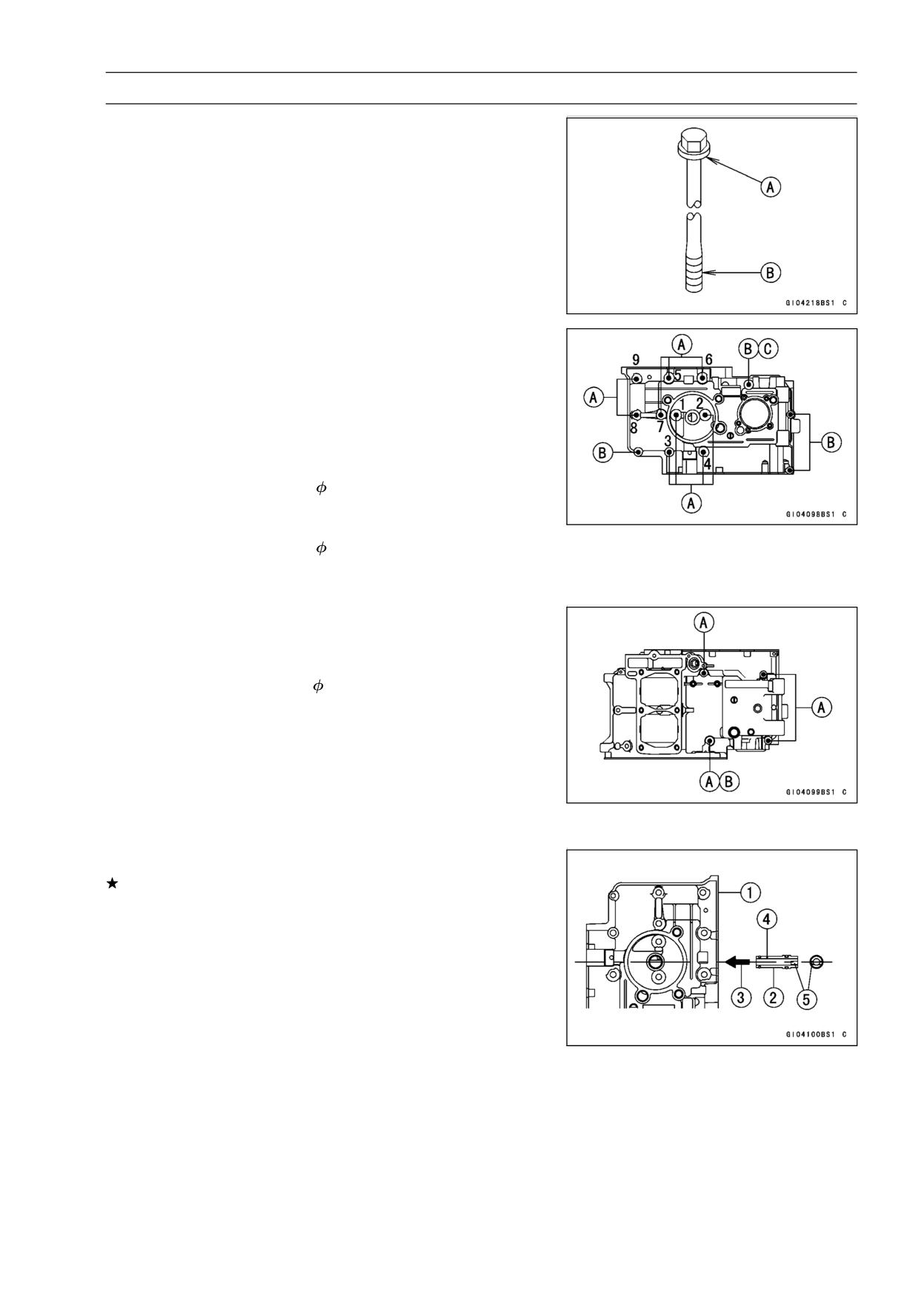
• Apply molybdenum disulfide oil solution to flange [A] and
the threads [B] of the M8 bolts which is tightening order is
[1 ∼ 8] only (see the next figure).
○Following the sequence numbers on the lower crankcase
half, tighten the 8 mm bolts [A] first to about one half of
the specified torque, and finally to the specified torque in
the same sequence.
○Replace the copper washer [C] with a new one.
○Tighten the 6 mm bolts [B] on the lower crankcase half to
the specified torque.
Torque - Crankcase Bolts (
8, L = 90):
First: 10 N·m (1.0 kgf·m, 89 in·lb)
Final: 24 N·m (2.4 kgf·m, 18 ft·lb)
Crankcase Bolts (
8, L = 73):
First: 10 N·m (1.0 kgf·m, 89 in·lb)
Final: 19 N·m (1.9 kgf·m, 14 ft·lb)
○Replace the copper washer [B] with a new one.
○Tighten the 6 mm bolts [A] on the upper crankcase half to
the specified torque.
Torque - Crankcase Bolts (
6): 12 N·m (1.2 kgf·m, 104 in·lb)
• After tightening all crankcase bolts, check the following
items.
○Drive shaft and output shaft turn freely.
○While spinning the output shaft, shift the transmission
smoothly from 1st to 6th gear, and back,
○Unless the output shaft is turning, the transmission cannot
be shifted to 2nd gear or other higher gear positions.
Crankcase Exchange
If the crankcase is damaged, replace it with a new one.
• Remove the crankcase parts from the damaged case, and
install it to the new case. Pay attention to the following
items.
○When installing the oil passage plug must be inserted as
shown.
[1] Lower Crankcase Half
[2] Oil Passage Pipe
[3] Press
[4] Small Hall (Up)
[5] Slit (Horizontal)
○Fit the oil passage O-ring on the breather body. Replace
the O-ring with new ones, if deteriorated or damage. The
flat side of the O-ring must face down.
○Apply a non-permanent locking agent to the threads of
the breather bolts, and tighten them.
9-14 CRANKSHAFT/TRANSMISSION
Crankshaft and Connecting Rods
Crankshaft Removal
• Split the crankcase (see Crankcase Splitting).
• Take the crankshaft out of the upper crankcase.
Crankshaft Installation
• Install the removed parts in reverse of removal.
NOTE
○If the crankshaft is replaced with a new one, refer to the
Connecting Rod Big End Bearing Insert Selection in the
specifications.
NOTICE
If the crankshaft, bearing inserts, or crankcase
halves are replaced with new ones, select the bear-
ing inserts and check clearance with a plastigage
(press gauge) before assembling engine to be sure
the correct bearing inserts are installed.
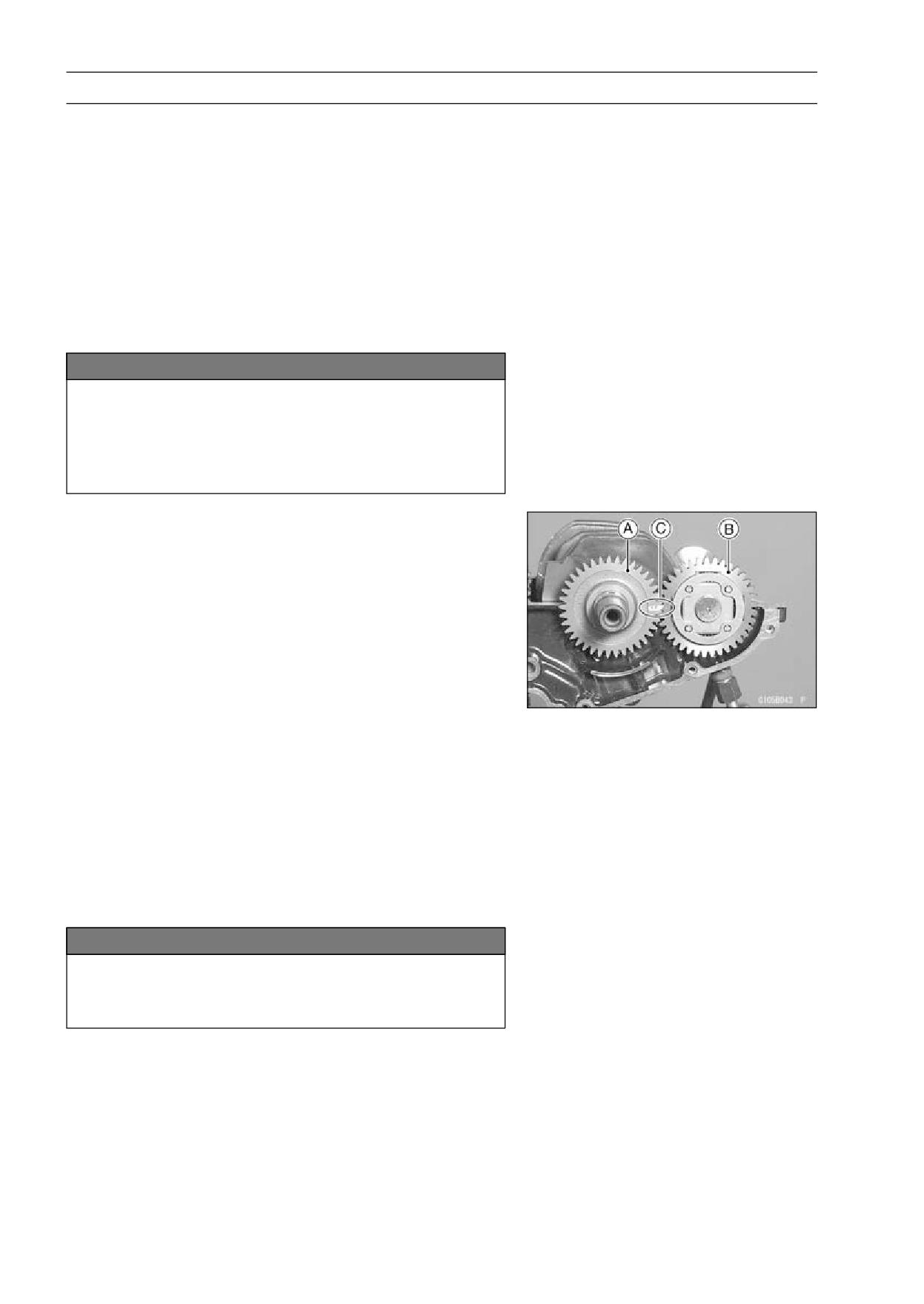
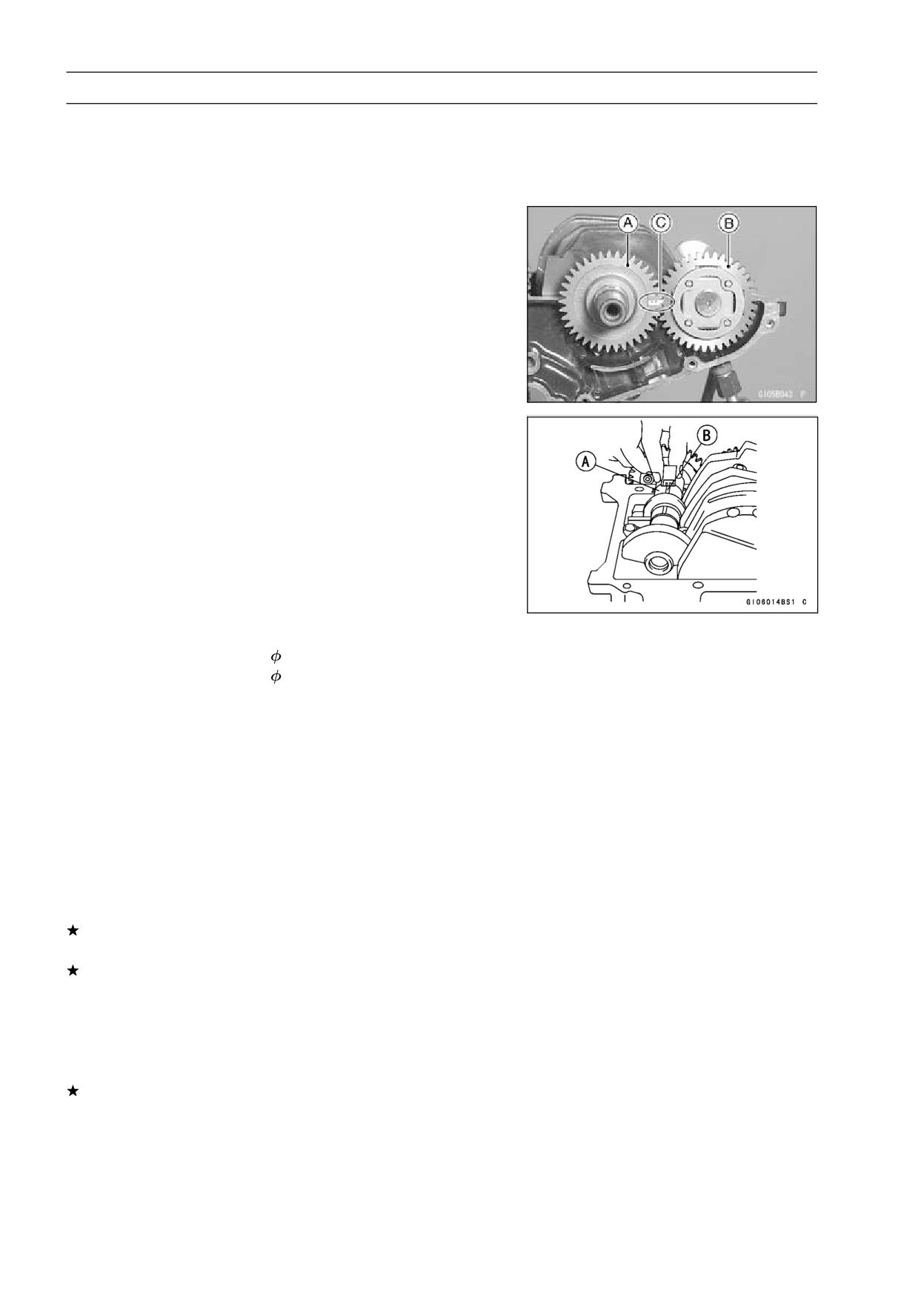
• Align the timing mark [C] on the balancer drive gear [A]
with the timing mark [C] on the balancer gear [B].
• Apply molybdenum disulfide oil solution to the crankshaft
main bearing inserts.
• Install the crankshaft.
Connecting Rod Removal
• Split the crankcase (see Crankcase Splitting).
• Remove the connecting rod big end cap nuts.
• Remove the crankshaft.
NOTE
○Mark and record the locations of the connecting rods
and their big end caps so that they can be reassembled
in their original positions.
• Remove the connecting rods from the crankshaft.
NOTICE
Discard the connecting rod bolts. To prevent dam-
age to the crankpin surfaces, do not allow the con-
necting rod bolts to bump against the crankpins.
CRANKSHAFT/TRANSMISSION 9-15
Crankshaft and Connecting Rods
Connecting Rod Installation
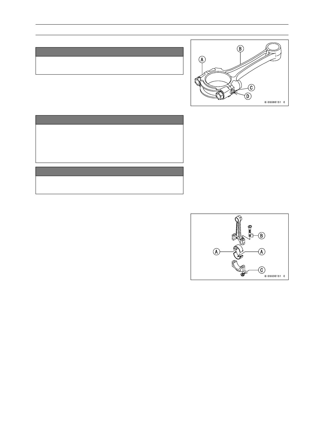
NOTICE
To minimize vibration, the connecting rods should
have the same weight mark.
Big End Cap [A]
Connecting Rod [B]
Weight Mark, Alphabet [C]
Diameter Mark (Around Weight Mark) [D]: “○” or no
mark
NOTICE
If the connecting rods, big end bearing inserts, or
crankshaft are replaced with new ones, select the
bearing insert and check clearance with a plasti-
gage (press gauge) before assembling engine to be
sure the correct bearing inserts are installed.
NOTICE
The connecting rod bolts are designed to stretch
when tightened. Never reuse them.
• Replace the connecting rod big end bolts and nuts with
new ones.
• Apply molybdenum disulfide oil solution to the inner sur-
face of upper and lower bearing inserts [A].
• Apply molybdenum disulfide oil solution to the threads [B]
and seating surface [C] of the connecting rod nuts.
Torque - Connecting Rod Big End Cap Nuts: 27.5 N·m (2.8
kgf·m, 20 ft·lb)
Crankshaft/Connecting Rod Cleaning
• After removing the connecting rods from the crankshaft,
clean them with a high-flash point solvent.
• Blow the crankshaft oil passages with compressed air to
remove any foreign particles or residue that may have
accumulated in the passages.
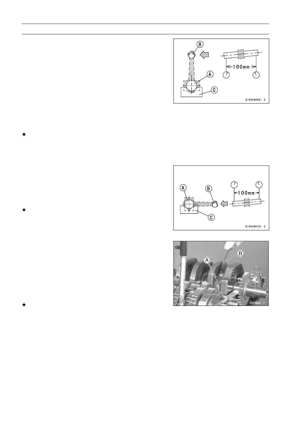
9-16 CRANKSHAFT/TRANSMISSION
Crankshaft and Connecting Rods
Connecting Rod Bend Inspection
• Remove the connecting rod big end bearing inserts, and
reinstall the connecting rod big end cap.
• Select an arbor [A] of the same diameter as the connect-
ing rod big end, and insert the arbor through the connect-
ing rod big end.
• Select an arbor of the same diameter as the piston pin
and at least 100 mm (3.94 in.) long, and insert the arbor
[B] through the connecting rod small end.
• On a surface plate, set the big-end arbor on V block [C].
• With the connecting rod held vertically, use a height
gauge to measure the difference in the height of the
arbor above the surface plate over a 100 mm (3.94 in.)
length to determine the amount of connecting rod bend.
If the connecting rod bend exceeds the service limit, the
connecting rod must be replaced.
Connecting Rod Bend
Service Limit: TIR 0.2/100 mm (0.008/3.94 in.)
Connecting Rod Twist Inspection
• With the big-end arbor [A] still on V block [C], hold the
connecting rod horizontally and measure the amount that
the arbor [B] varies from being paralleled with the surface
plate over a 100 mm (3.94 in.) length of the arbor to de-
termine the amount of connecting rod twist.
If the connecting rod twist exceeds the service limit, the
connecting rod must be replaced.
Connecting Rod Twist
Service Limit: TIR 0.2/100 mm (0.008/3.94 in.)
Connecting Rod Big End Side Clearance
Inspection
• Measure the connecting rod big end side clearance [A].
○Insert a thickness gauge [B] between the big end and the
crank web to determine clearance.
Connecting Rod Big End Side Clearance
Standard:
0.13 ∼ 0.38 mm (0.005 ∼ 0.015 in.)
Service Limit: 0.58 mm (0.023 in.)
If the clearance exceeds the service limit, replace the con-
necting rod with new one and then check the clearance
again. If the clearance is too large after connecting rod
replacement, the crankshaft also must be replaced.
CRANKSHAFT/TRANSMISSION 9-17
Crankshaft and Connecting Rods
Connecting Rod Big End Bearing Insert/Crankpin
Wear Inspection
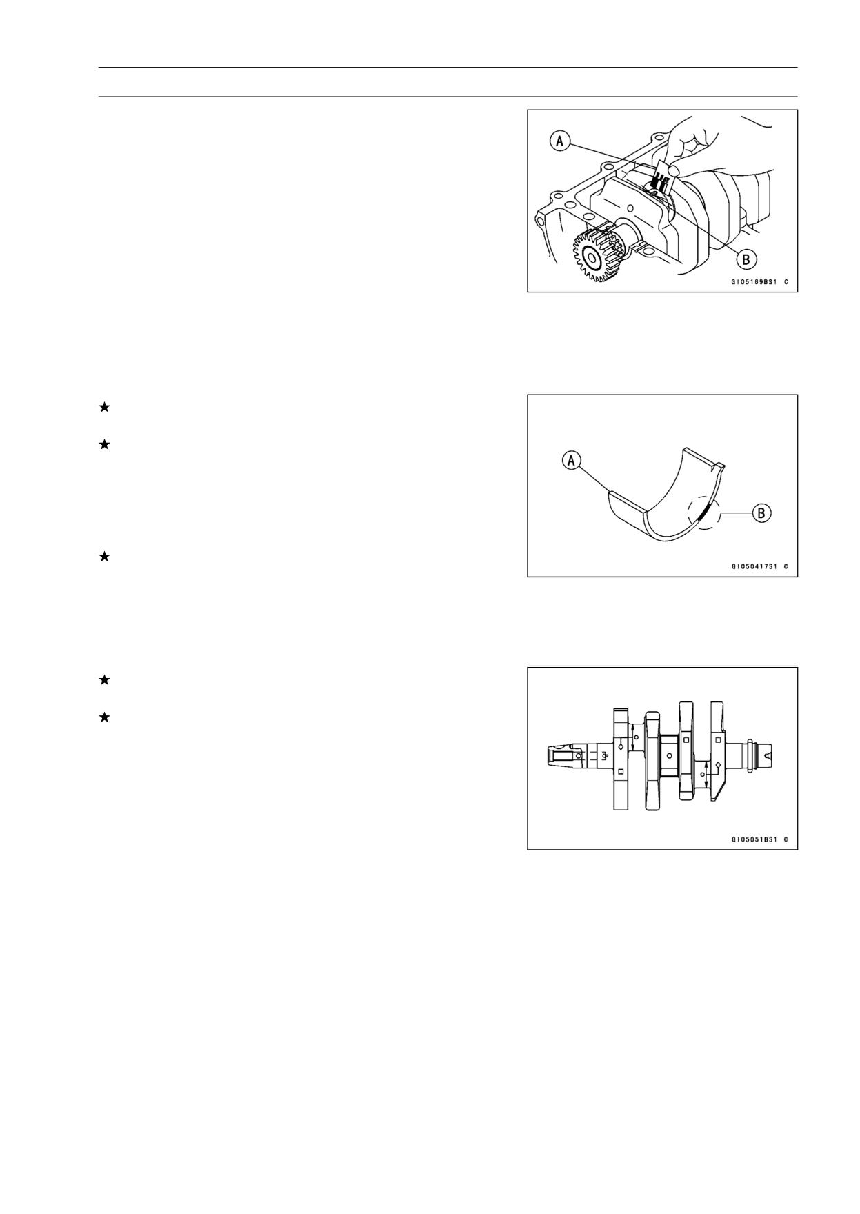
• Measure the bearing insert/crankpin clearance [B] with
plastigage [A].
• Tighten the big end nuts to the specified torque (see Con-
necting Rod Installation).
NOTE
○Do not move the connecting rod and crankshaft during
clearance measurement.
Connecting Rod Big End Bearing Insert/Crankpin
Clearance
Standard:
0.031 ∼ 0.059 mm (0.0012 ∼ 0.0023 in.)
Service Limit: 0.10 mm (0.004 in.)
If the clearance is within the standard, no bearing replace-
ment is required.
If the clearance is between 0.059 mm (0.0023 in.) and
the service limit 0.10 mm (0.004 in.), replace the bear-
ing inserts [A] with inserts painted black [B]. Check the
insert/crankpin clearance with the plastigage. The clear-
ance may exceed the standard slightly, but it must not be
less than the minimum in order to avoid bearing seizure.
If the clearance exceeds the service limit, measure the
diameter of the crankpins.
Crankpin Diameter
Standard:
29.984 ∼ 30.000 mm (1.1805 ∼ 1.1811 in.)
Service Limit: 29.97 mm (1.18 in.)
If any crankpin has worn past the service limit, replace the
crankshaft with a new one.
If the measured crankpin diameters are not less than the
service limit, but do not coincide with the original diameter
markings on the crankshaft, make new marks on it.
Crankpin Diameter Marks
None: 29.984 ∼ 29.994 mm (1.1805 ∼ 1.1809 in.)
○:
29.995 ∼ 30.000 mm (1.1809 ∼ 1.1811 in.)
◊: Crankpin Diameter Marks, "○" mark or no mark.
9-18 CRANKSHAFT/TRANSMISSION
Crankshaft and Connecting Rods
• Measure the connecting rod big end bore diameter, and
mark each connecting rod big end in accordance with the
bore diameter.
• Tighten the big end nuts to the specified torque (see Con-
necting Rod Installation).
NOTE
○The mark already on the big end should almost coincide
with the measurement because of little wear.
Connecting Rod Big End Bore Diameter Marks
None: 33.000 ∼ 33.008 mm (1.2992 ∼ 1.2995 in.)
○:
33.009 ∼ 33.016 mm (1.2996 ∼ 1.2998 in.)
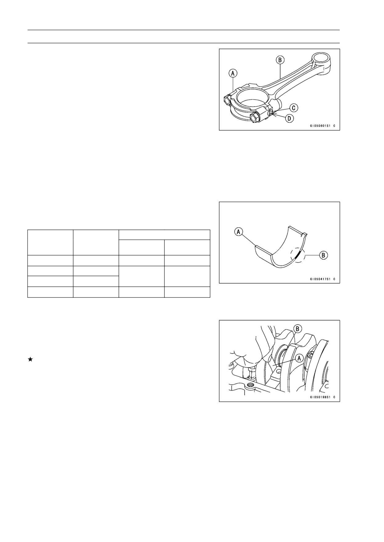
Big End Cap [A]
Connecting Rod [B]
Weight Mark, Alphabet [C]
Diameter Mark (Around Weight Mark) [D]: “○” or no
mark
• Select the proper bearing insert [A] in accordance with the
combination of the connecting rod and crankshaft coding.
Size Color [B]
Con-rod Bid
Crankpin
Bearing Insert
End Bore
Diameter
Size Color
Part Number
Diameter
Marking
None
○
Brown
92028-1494
None
None
Black
92028-1493
○
○
○
None
Blue
92028-1492
• Install the new inserts in the connecting rod and check
insert/crankpin clearance with the plastigage.
Crankshaft Side Clearance Inspection
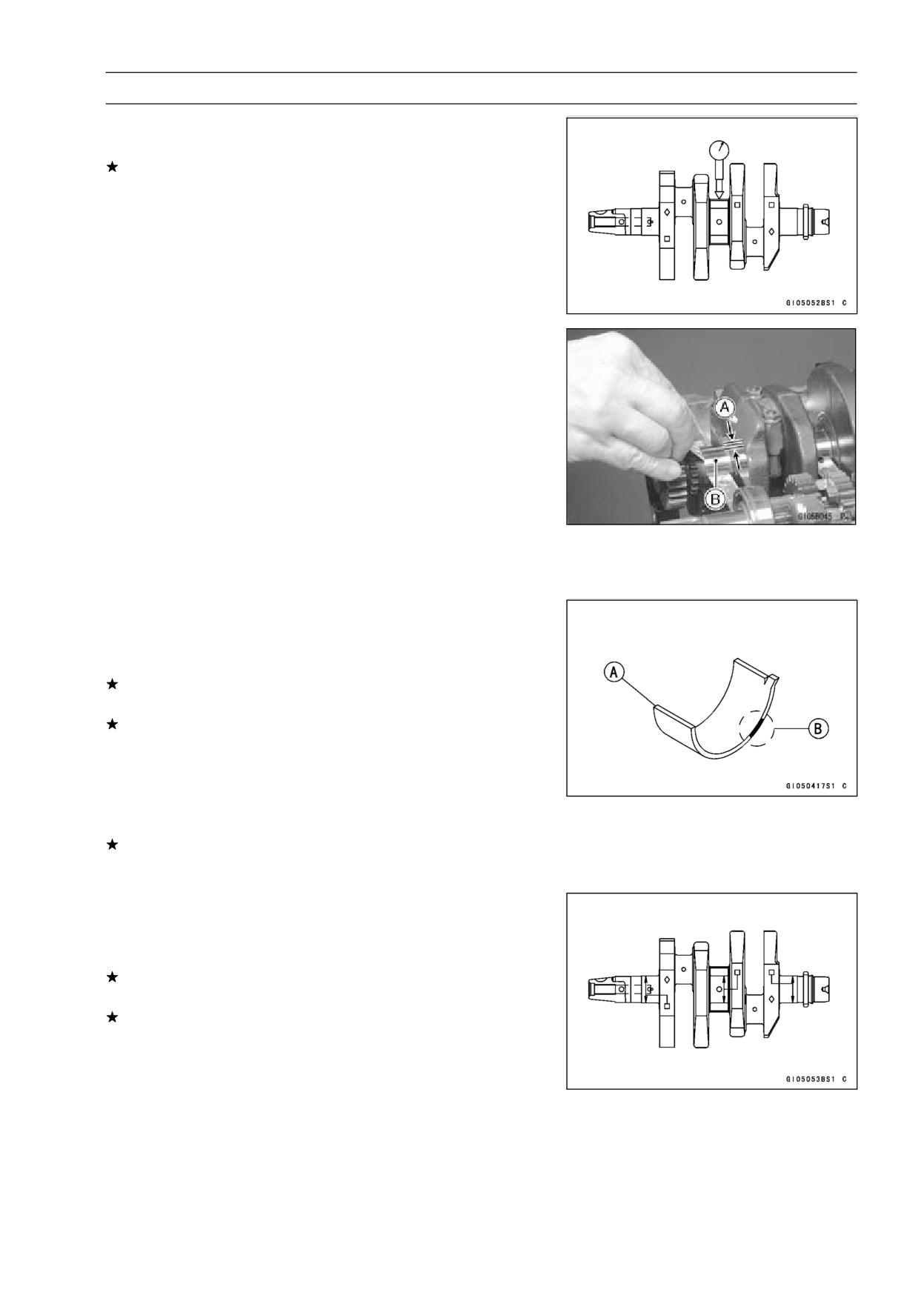
• Insert a thickness gauge [A] between the crankcase main
bearing and the crank web at the No. 2 journal [B] to
determine clearance.
If the clearance exceeds the service limit, replace the
crankcase halves as a set.
NOTE
○The upper and lower crankcase halves are machined
at the factory in the assembled state, so the crankcase
halves must be replaced as a set.
Crankshaft Side Clearance
Standard:
0.05 ∼ 0.20 mm (0.002 ∼ 0.008 in.)
Service Limit:
0.40 mm (0.016 in.)
CRANKSHAFT/TRANSMISSION 9-19
Crankshaft and Connecting Rods
Crankshaft Runout Inspection
• Measure the crankshaft runout.
If the measurement exceeds the service limit, replace the
crankshaft.
Crankshaft Runout
Standard:
TIR 0.02 mm (0.0008 in.) or less
Service Limit: TIR 0.05 mm (0.002 in.)
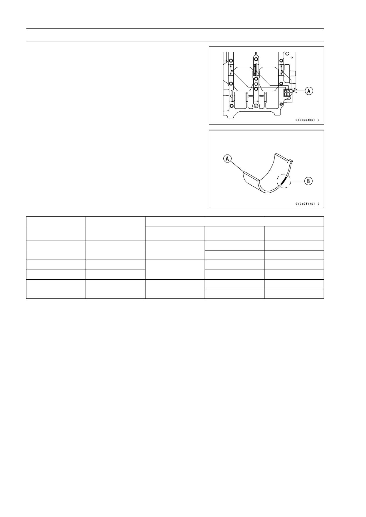
Crankshaft Main Bearing Insert/Journal Wear
Inspection
• Using a plastigage (press gauge), measure the bearing
insert/journal [B] clearance [A].
NOTE
○Tighten the crankcase bolts to the specified torque (see
Crankcase Assembly).
○Do not turn the crankshaft during clearance measure-
ment.
○Journal clearance less than 0.025 mm (0.001 in.) can
not be measured by plastigage, however, using genuine
parts maintains the minimum standard clearance.
Crankshaft Main Bearing Insert/Journal Clearance
Standard:
0.014 ∼ 0.038 mm (0.0006 ∼ 0.0015 in.)
Service Limit: 0.07 mm (0.0028 in.)
If the clearance is within the standard, no bearing replace-
ment is required.
If the clearance is between 0.038 mm (0.0015 in.) and the
service limit 0.07 mm (0.0028 in.), replace the bearing in-
serts [A] with inserts painted blue [B]. Check insert/journal
clearance with the plastigage. The clearance may exceed
the standard slightly, but it must not be less than the min-
imum in order to avoid bearing seizure.
If the clearance exceeds the service limit, measure the
diameter of the crankshaft main journal.
Crankshaft Main Journal Diameter
Standard:
27.984 ∼ 28.000 mm (1.1017 ∼ 1.1024 in.)
Service Limit: 27.96 mm (1.101 in.)
If any journal has worn past the service limit, replace the
crankshaft with a new one.
If the measured journal diameters are not less than the
service limit, but do not coincide with the original diameter
markings on the crankshaft, make new marks on it.
Crankshaft Main Journal Diameter Marks
None: 27.984 ∼ 27.992 mm (1.1017 ∼ 1.1020 in.)
1:
27.993 ∼ 28.000 mm (1.1021 ∼ 1.1024 in.)
□: Crankshaft Main Journal Diameter Marks, "1" mark
or no mark.
9-20 CRANKSHAFT/TRANSMISSION
Crankshaft and Connecting Rods
• Measure the main bearing bore diameter, and mark the
upper crankcase half in accordance with the bore diame-
ter.
A: Crankcase Main Bearing Bore Diameter Marks, "○"
mark or no mark.
NOTE
○Tighten the crankcase bolts to the specified torque (see
Crankcase Assembly).
○The mark already on the upper crankcase half should
almost coincide with the measurement.
Crankcase Main Bearing Bore Diameter Marks
○:
31.000 ∼ 31.008 mm (1.2205 ∼ 1.2208 in.)
None: 31.009 ∼ 31.016 mm (1.2208 ∼ 1.2211 in.)
• Select the proper bearing insert [A] in accordance with the
combination of the crankcase and crankshaft coding.
Size Color [B]
Crankcase Main
Crankshaft Main
Bearing Insert*
Bearing Bore
Journal Diameter
Size Color
Part Number
Journal Nos.
Diameter Marking
Marking
92028-1487
1, 3
○
1
Black
92028-1490
2
None
1
92028-1486
1, 3
Blue
○
None
92028-1489
2
92028-1582
1, 3
None
None
Yellow
92028-1586
2
*The bearing insert for No.2 journal have an oil groove.
• Install the new inserts in the crankcase halves and check
insert/journal clearance with the plastigage.
CRANKSHAFT/TRANSMISSION 9-21
Starter Motor Clutch
Starter Motor Clutch Removal/Installation
• Refer to Alternator Rotor Removal and Installation in the
Electrical System chapter (see Alternator Rotor Removal
and Installation in the Electrical System chapter).
Starter Motor Clutch Inspection
• Remove:
Alternator Cover (see Alternator Cover Removal in the
Electrical System chapter)
Starter Idle Gear
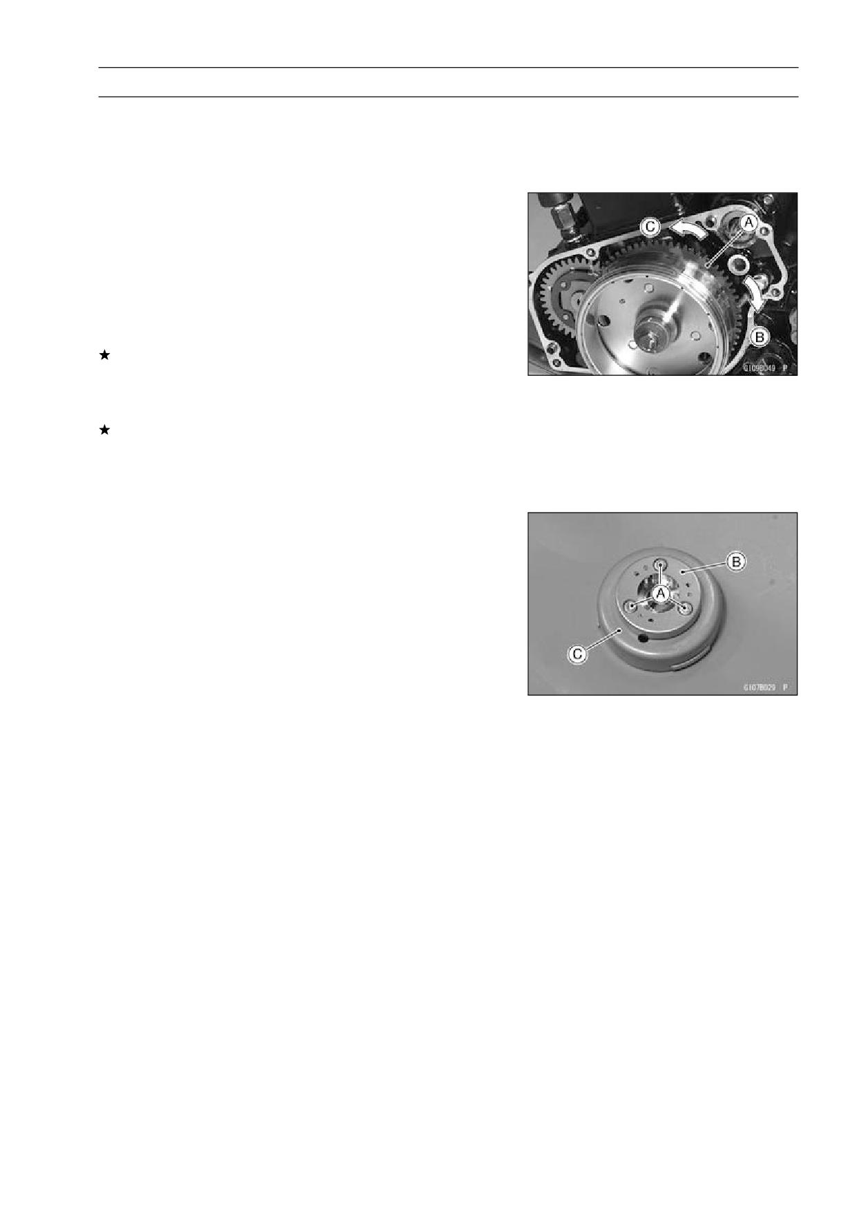
• Turn the starter motor clutch gear [A] by hand. The starter
motor clutch gear should turn clockwise [B] freely, but
should not turn counterclockwise [C].
If the starter motor clutch does not operate as it should or
if it makes noise, go to the next step.
• Disassemble the starter motor clutch, and visually inspect
the clutch parts.
If there is any worn or damaged part, replace it.
NOTE
○Examine the starter motor clutch gear as well. Replace
it if is worn or damage.
Starter Motor Clutch Disassembly
• Remove:
Alternator Rotor (see Alternator Rotor Removal in the
Electrical System chapter)
Starter Motor Clutch Bolts [A] and Starter Motor Clutch
[B]
Alternator Rotor [C]
Starter Motor Clutch Assembly
• Apply a non-permanent locking agent to the threads of
the starter motor clutch bolts and tighten them.
Torque - Starter Motor Clutch Bolts: 34.3 N·m (3.5 kgf·m,
25 ft·lb)
9-22 CRANKSHAFT/TRANSMISSION
Balancer
Balancer Removal
• Split the crankcase (see Crankcase Splitting).
• Pull the balancer shaft with the balancer gear out of the
crankcase.
Balancer Installation
• Balancer installation is the reverse of removal.
• Apply oil to the inside of the balancer shaft bearing insert.
• Align the timing mark [C] on the balancer gear [B] with
the timing mark [C] on the balancer drive gear [A] of the
crankshaft.
Balancer Shaft Bearing Insert/Journal Wear
Inspection
• Measure the bearing insert/journal clearance.
○Split the crankcase and wipe each bearing insert and jour-
nal [A] surface clean of oil.
○Cut strips of plastigage (press gauge) [B] to bearing insert
width, and place a strip on each journal parallel to the
balancer shaft so that the plastigage will be compressed
between the journal and the bearing insert.
○Install the lower crankcase half, and tighten the case bolts
to the specified torque.
Torque - Crankcase Bolts
8: 27 N·m (2.8 kgf·m, 20 ft·lb)
Crankcase Bolts
6: 12 N·m (1.2 kgf·m, 104 in·lb)
NOTE
○Do not turn the balancer shaft during clearance mea-
surement.
○Remove the lower crankcase half and measure the plas-
tigage width to determine the bearing insert/journal clear-
ance.
Balancer Shaft Bearing Insert/Journal Clearance
Standard:
0.020 ∼ 0.044 mm (0.0008 ∼ 0.0017 in.)
Service Limit: 0.07 mm (0.0028 in.)
If the clearance is within the standard, no bearing replace-
ment is required.
If the clearance is between 0.044 mm (0.0017 in.) and
the service limit 0.07 mm (0.0028 in.), replace the bear-
ing inserts with inserts painted blue. Check insert/journal
clearance with the plastigage. The clearance may exceed
the standard slightly, but it must not be less than the min-
imum in order to avoid bearing seizure.
If the clearance exceeds the service limit, measure the
diameter of the balancer shaft journal.
Balancer Shaft Journal Diameter
Standard:
25.984 ∼ 26.000 mm (1.0230 ∼ 1.0236 in.)
Service Limit:
25.96 mm (1.022 in.)
CRANKSHAFT/TRANSMISSION 9-23
Balancer
If either journal has worn past the service limit, replace
the balancer shaft with a new one.
If the measured journal diameter is not less than the ser-
vice limit, but does not coincide with the original diameter
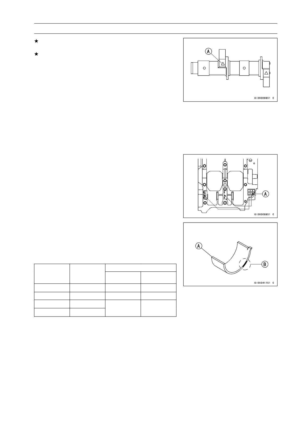
markings [A] on the balancer shaft, make new marks on
it.
Balancer Shaft Journal Diameter Marks
None: 25.984 ∼ 25.994 mm (1.0230 ∼ 1.0234 in.)
○:
25.995 ∼ 26.000 mm (1.0234 ∼ 1.0236 in.)
• Put the lower crankcase half on the upper crankcase half
without bearing inserts, and tighten the case bolts to the
specified torque and sequence (see Crankcase Assem-
bly).
• Measure the main bearing inside diameter, and mark the
upper crankcase half in accordance with the inside diam-
eter.
NOTE
○The mark [A] already on the upper crankcase half
should almost coincide with the measurement.
Crankcase Bearing Inside Diameter Marks
○:
29.000 ∼ 29.008 mm (1.1417 ∼ 1.1420 in.)
None: 29.009 ∼ 29.016 mm (1.1421 ∼ 1.1424 in.)
• Select the proper bearing inserts [A] in accordance with
the combination of the crankcase and balancer shaft cod-
ing.
• Install the new inserts in the crankcase and check in-
sert/journal clearance with the plastigage.
Size Color [B]
Crankcase
Balancer
Bearing Insert
Bearing Inside
Shaft Journal
Part Number
Diameter Mark
Diameter MarkSizeColor
○
○
Brown
92028-1424
None
None
Blue
92028-1422
○
None
Black
92028-1423
None
○
9-24 CRANKSHAFT/TRANSMISSION
Transmission
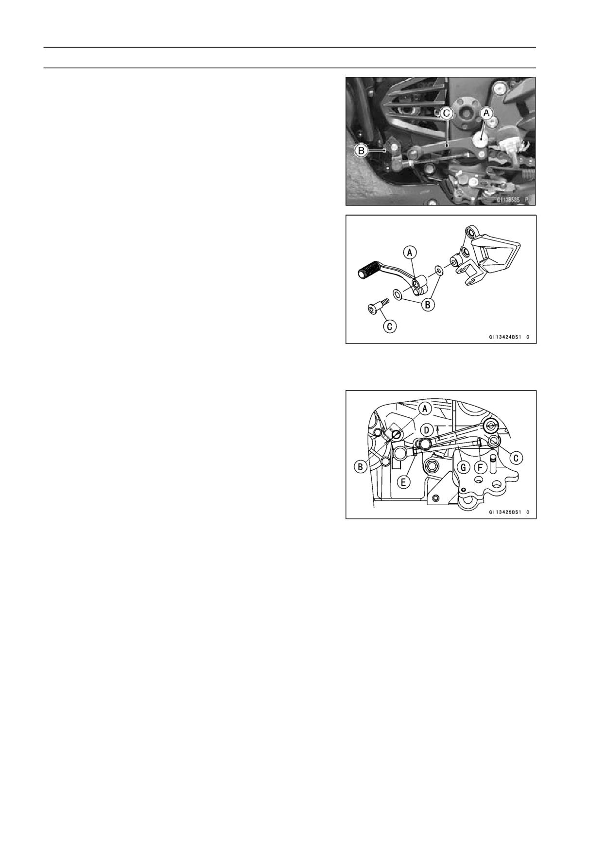
Shift Pedal Removal
• Remove:
Shift Pedal Mounting Bolt [A]
Shift Lever Bolt [B]
Shift Pedal [C] with Shift Lever
Shift Pedal Installation
• Apply grease to the shift pedal [A].
• Install the washers [B] and shift pedal.
• For EX250J8 ∼ JB (with a non-permanent locking agent)
models, apply a non-permanent locking agent to the shift
pedal mounting bolt [C], and tighten it.
Torque - Shift Pedal Mounting Bolt: 20 N·m (2.0 kgf·m, 15
ft·lb)
• For EX250JB ∼ JC (without a non-permanent locking
agent) models, tighten the shift pedal mounting bolt.
Torque - Shift Pedal Mounting Bolt: 25 N·m (2.5 kgf·m, 18
ft·lb)
• Align the mark [A] on the shift shaft with the mark [B] on
the shift lever.
• Tighten:
Torque - Shift Lever Link Bolt: 12 N·m (1.2 kgf·m, 106 in·lb)
• Install the shift pedal [C] as shown in the figure.
About 16° [D]
○To adjust the pedal position, loosen the front locknut [E]
(left-hand threads) and rear locknut [F] and then turn the
tie-rod [G].
• Tighten:
Torque - Tie-Rod Locknuts: 7.0 N·m (0.71 kgf·m, 62 in·lb)
CRANKSHAFT/TRANSMISSION 9-25
Transmission
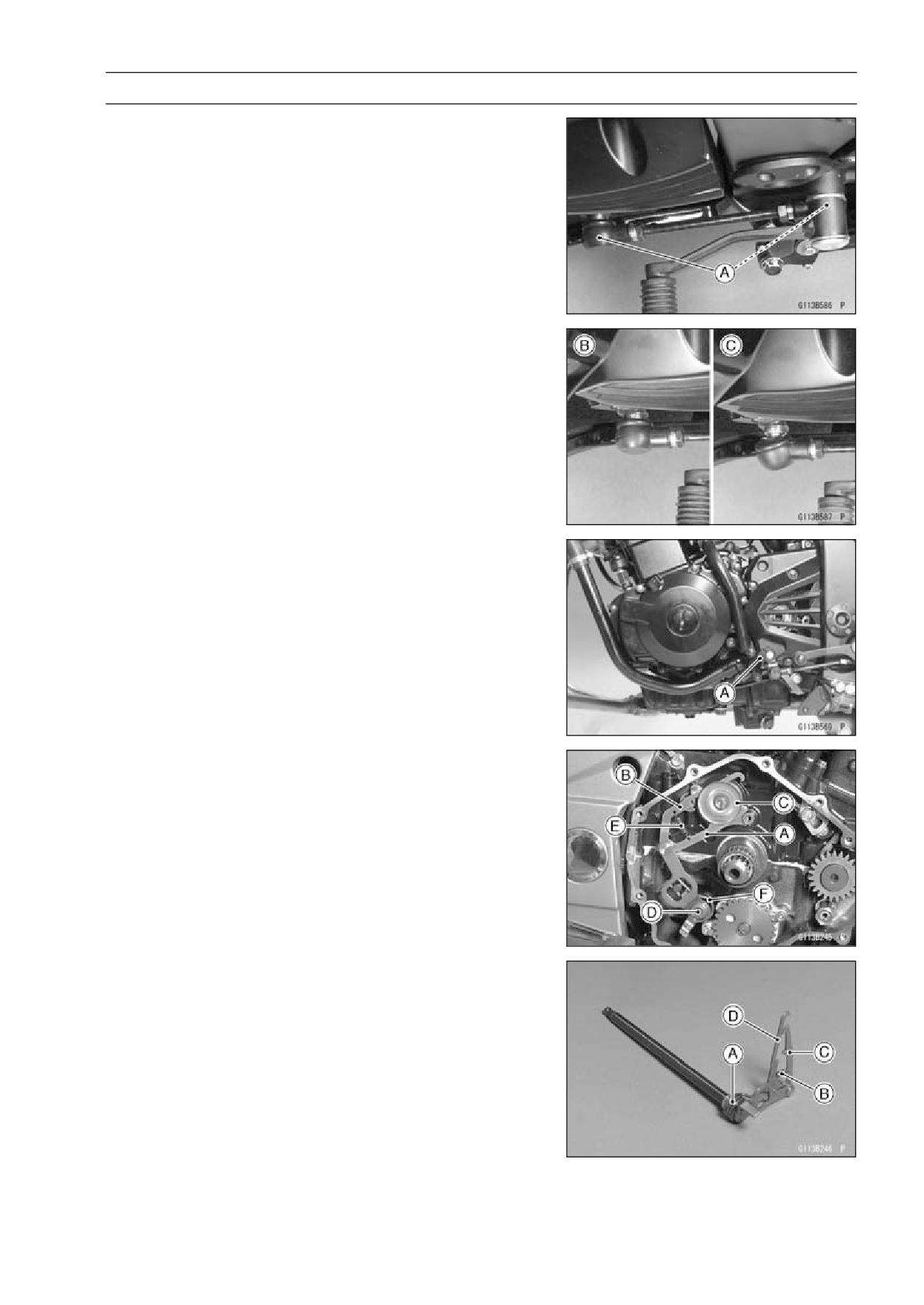
• Be sure the sealing lip of the rubber boots [A] fits into the
groove of the ball joint after installing the shift lever link.
Correctly Boot Fitting Position [B]
Incorrectly Boot Fitting Position [C]
External Shift Mechanism Removal
• Drain the engine oil (see Engine Oil Change in the Peri-
odic Maintenance chapter).
• Remove the shift lever link bolt [A] and pull the lever link
off the shift shaft end.
• Remove the clutch (see Clutch Removal in the Clutch
chapter).
• Move the shift mechanism arm [A] and over shift limiter
[B] out of their positions on the end of the shift drum [C],
and pull out the shift shaft [D] with the arm, pawl spring
[E] and return spring [F].
External Shift Mechanism Installation
• Check that the return spring [A] and pawl spring [B] are
properly fitted on the mechanism, install the external shift
mechanism, and place the shift mechanism arm [C] and
over shift limiter [D] on the shift drum pins.
• Add the engine oil (see Lubrication System in the Periodic
Maintenance chapter).
9-26 CRANKSHAFT/TRANSMISSION
Transmission
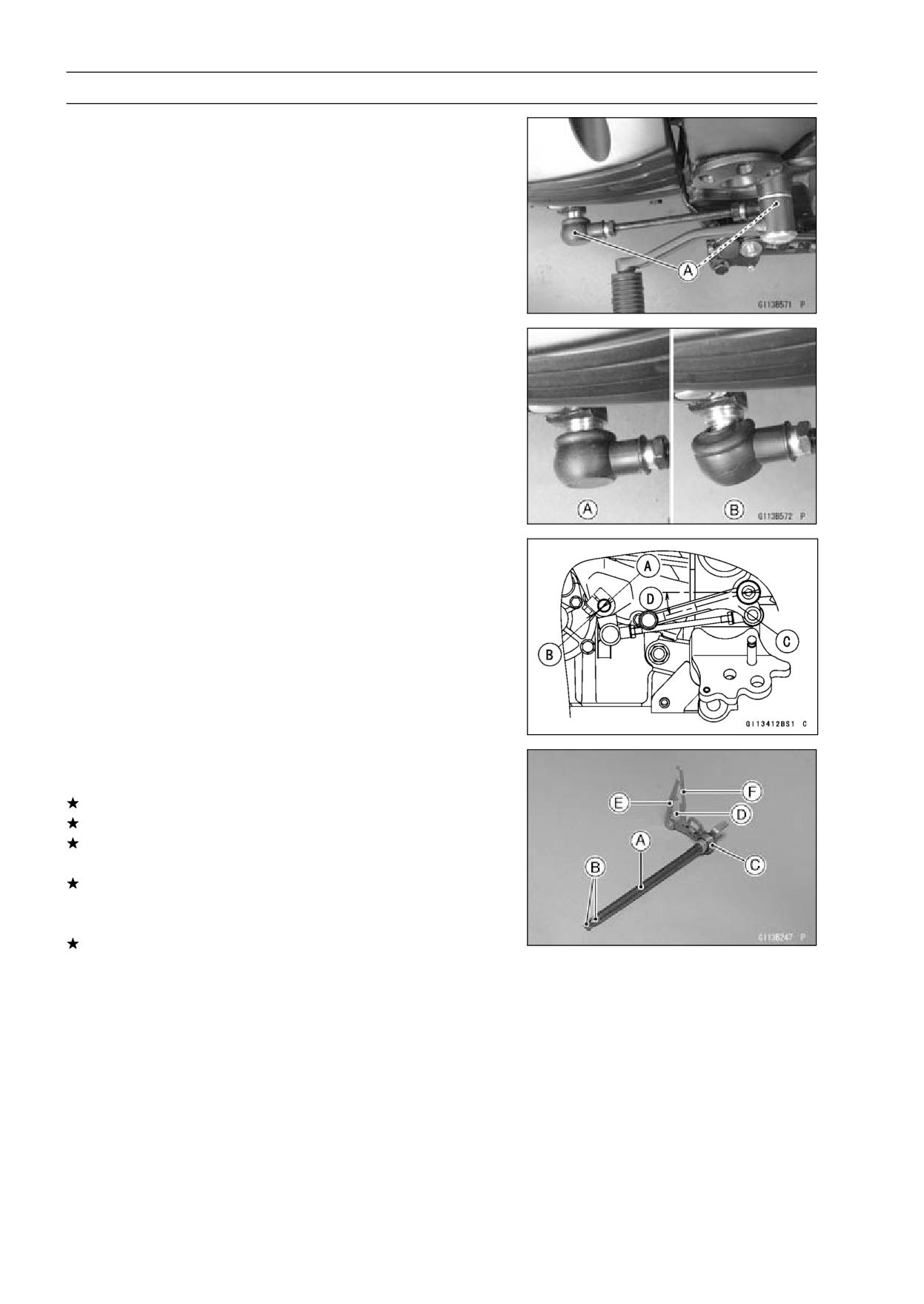
• Be sure the sealing lip of the rubber boot [A] fits into the
groove of the ball joint after installing the shift lever link.
○Correctly Boot Fitting Position [A]
○Incorrectly Boot Position [B]
• Align the mark [A] on the shift shaft with the mark [B] on
the shift lever link.
• Position the shift lever [C] as shown.
Approx. 15° [D]
External Shift Mechanism Inspection
• Examine the shift shaft for any damage.
If the shift shaft [A] is bent, straighten or replace it.
If the splines [B] are damaged, replace the shaft.
If the return spring [C] or pawl spring [D] is broken or dis-
torted, replace them.
If the shift mechanism arm [E] or over shift limiter [F] is
distorted, replace the shift shaft.
• Check the return spring pin is not loose.
If it is loose, unscrew it and apply a non-permanent lock-
ing agent to the threads, and tighten it.
Torque - External Shift Mechanism Return Spring Pin: 19.6
N·m (2.0 kgf·m, 14.5 ft·lb)
CRANKSHAFT/TRANSMISSION 9-27
Transmission
• Visually inspect the shift drum pins [A], pin holder [B] and
pin plate [C].
If they are badly worn or if they show any damage, replace
them.
Transmission Removal
• Split the crankcase (see Crankcase Splitting).
• Remove the drive shaft [A] and output shaft [B].
Transmission Installation
• With a high flash-point solvent, clean off the outer cir-
cumferences of the transmission ball bearings and needle
bearing housings, and wipe dry.
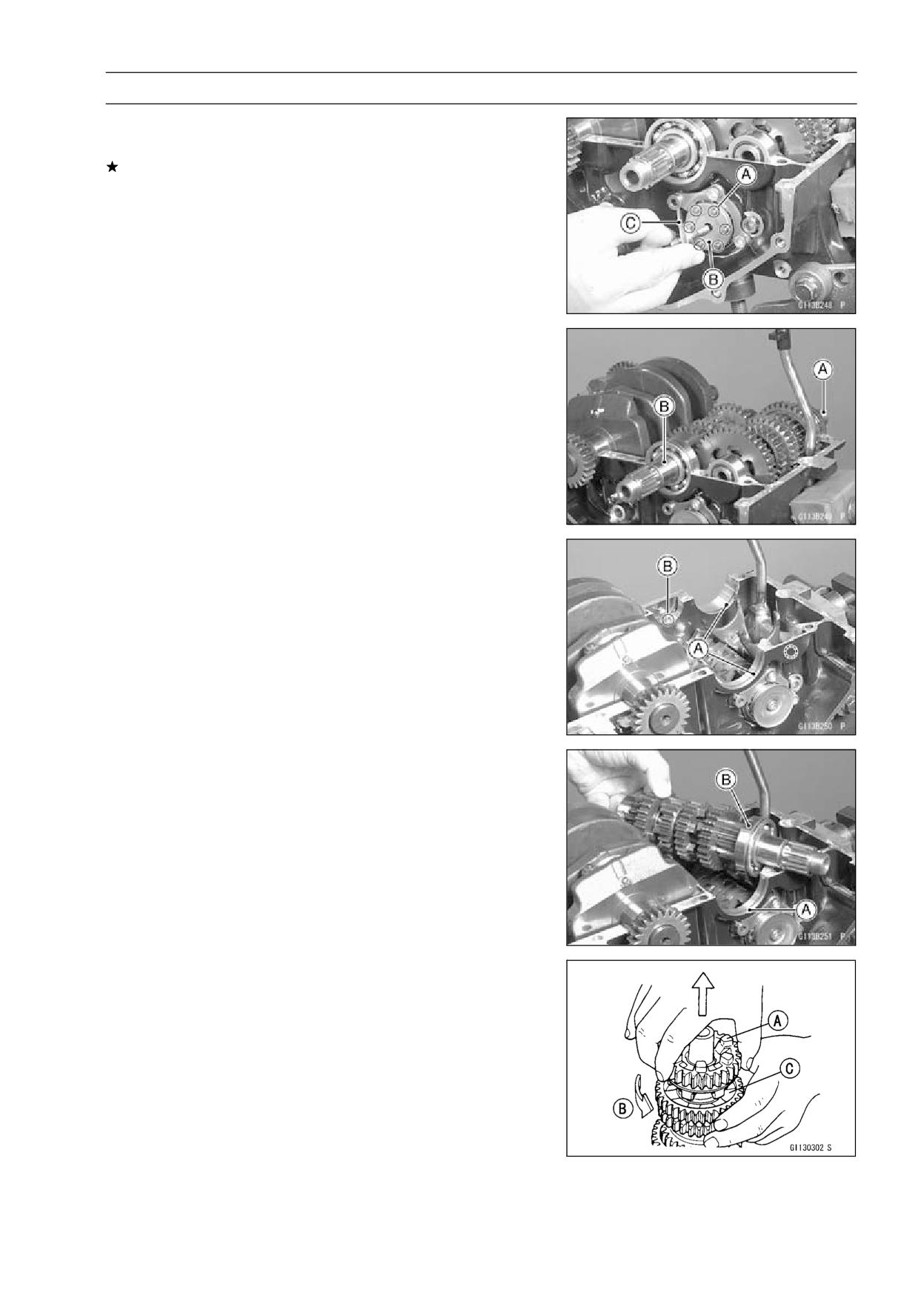
• Check to see that the set rings [A] and set pins [B] are
in place in the transmission bearing housings clean with
compressed air.
• Install the drive shaft and output shaft into the upper
crankcase half.
• Apply engine oil to the sliding surfaces of the gears and
bearings.
○The bearing set pins and rings must match properly with
the holes or grooves in the bearing outer races. When
they are properly matched, there is no clearance between
the crankcase [A] and the bearing outer races [B].
• Assemble the crankcase.
Transmission Shaft Disassembly
• Remove the transmission shafts (see Transmission Shaft
Removal).
• Remove the circlips, disassemble the transmission
shafts.
Special Tool - Outside Circlip Pliers: 57001-144
• The 5th gear [A] on the output shaft has three steel balls
assembled into it for the positive neutral finder mecha-
nism. Remove the 5th gear.
○Set the output shaft in a vertical position holding the 3rd
gear [C].
○Spin the 5th gear quickly [B] and pull it off upward.
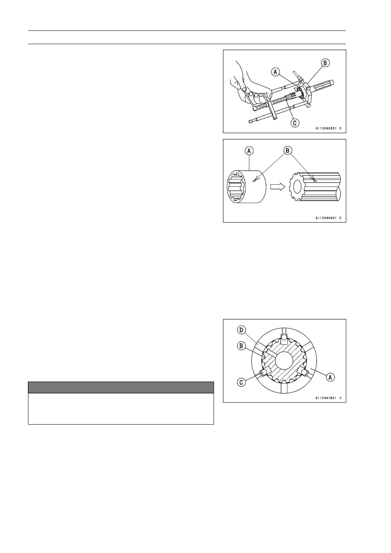
9-28 CRANKSHAFT/TRANSMISSION
Transmission
• Remove the ball bearing [A] from each shafts.
Special Tools - Bearing Puller: 57001-135 [B]
Bearing Puller Adapter: 57001-317 [C]
• Discard the bearing.
Transmission Shaft Assembly
• Install the ball bearing on the drive shaft with the groove
toward the clutch side.
• Install the gear bushing [A] on the shafts with their oil
holes [B] aligned.
• The drive shaft gears can be recognized by size: the gear
with the smallest diameter is 1st gear, and the largest one
is 6th gear. Be sure that all parts are put back in the cor-
rect sequence and all circlips and washers are properly in
place.
• The output shaft gears can be recognized by size: the
gear with the largest diameter is 1st gear, and the small-
est one is 6th gear. Be sure that all parts are put back
in the correct sequence and all circlips and washers are
properly in place.
• Fit the steel balls into the 5th gear holes in the output shaft
as shown.
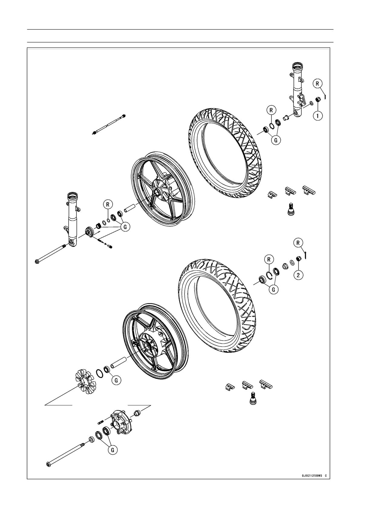
View A - A’ (see CRANKSHAFT/TRANSMISSION 9-33)
5th Gear [A]
Output Shaft [B]
Steel Balls [C]
Oil Hole [D]
NOTICE
Do not apply grease to the steel balls to hold them
in place. This will cause the positive neutral finder
mechanism to malfunction.
○Check the ball-locking effect that the 5th gear does not
come out of the output shaft when moving it up and down
by hand.
CRANKSHAFT/TRANSMISSION 9-29
Transmission
• Replace any circlip that were removed with new ones.
• Install the circlips [A] so that opening [B] is aligned with a
spline groove [C].
• Check that each gear spins or slides freely on the trans-
mission shafts without binding after assembly.
Shift Drum and Fork Removal
• Split the crankcase (see Crankcase Splitting).
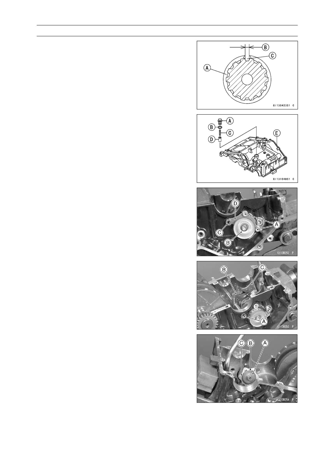
• Remove the neutral positioning bolt [A] and take off
the washer [B], spring [C] and pin [D] from the upper
crankcase half [E].
• Remove the shift drum bearing holder bolts [A] and take
the holder plate [D] out of the shift drum [B] and shift rod
[C].
• Pull the shift rods [A] off the right side of the upper
crankcase half, and take off the drive shaft shift fork [B]
and the output shaft shift forks [C].
• Pull out the shift drum [A] about half of it, and remove the
circlip [B] and the operating plate [C].
• Pull out the shift drum fully from the upper crankcase.
9-30 CRANKSHAFT/TRANSMISSION
Transmission
Shift Drum and Fork Installation
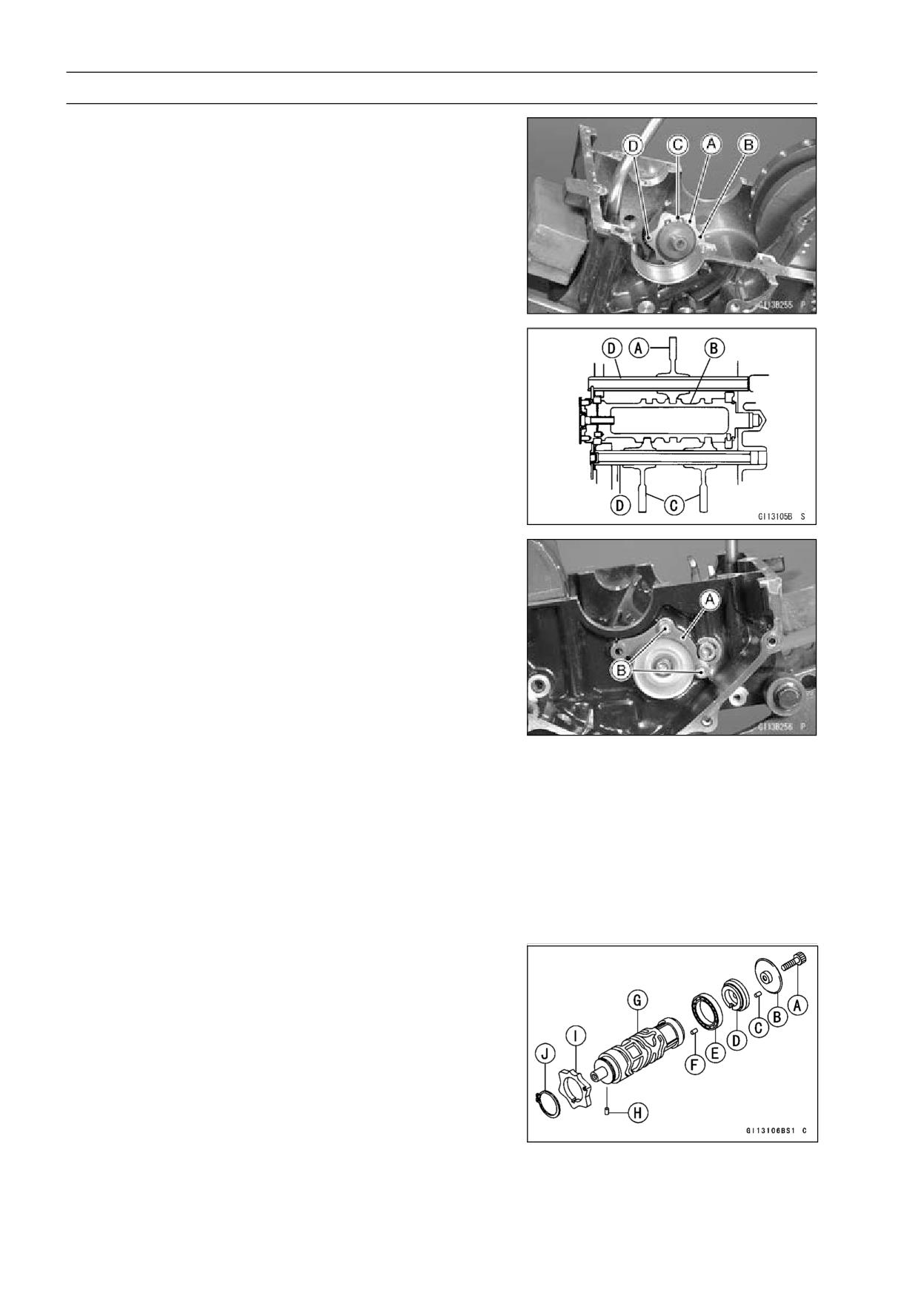
• Set the transmission gear in the neutral position.
• Insert the shift drum into the upper crankcase half, and
install the operating plate pin [A], operating plate [B] and
circlip [C].
NOTE
○When installing the operating plate the projection [D]
faces toward the outside.
• Apply a little engine oil to the shift rods and shift fork fin-
gers.
• Insert the shift rods [D] running them through the shift
forks, fitting each shift fork guide pin into the shift drum
grooves.
○Position the one with shortest ear [A] on the drive shaft
and place the guide pin in the center groove in the shift
drum [B].
○The two forks [C] on the output shaft are identical.
• Install the shift drum bearing holder plate [A].
○Apply a non-permanent locking agent to the threads of
the shift drum bearing holder bolts [B], and tighten them
with the specified torque.
Torque - Shift Drum Bearing Holder Bolts:
12 N·m (1.2
kgf·m, 104 in·lb)
• Install the neutral positioning bolt with the specified torque
to the upper crankcase.
Torque - Shift Drum Positioning Bolt: 24.5 N·m (2.5 kgf·m,
18 ft·lb)
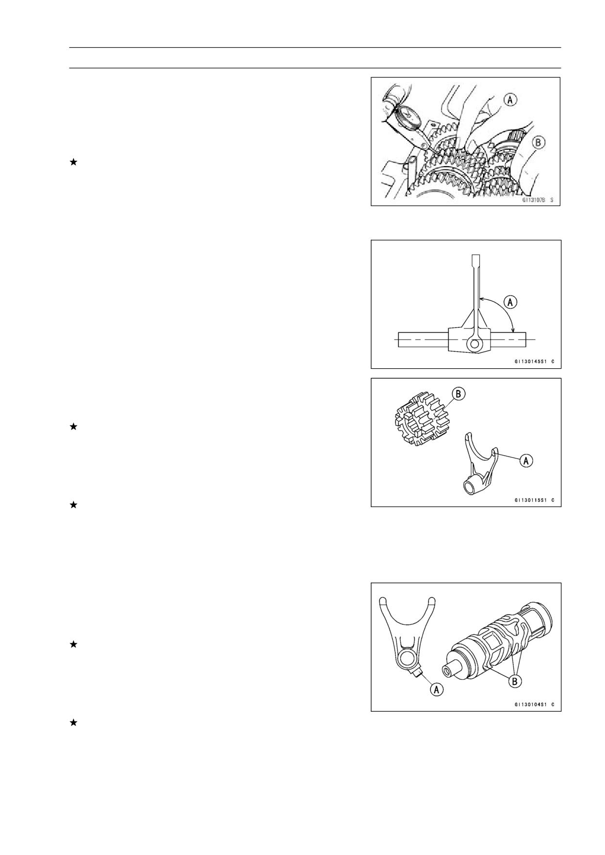
Shift Drum Disassembly
• Remove the shift drum (see Shift Drum Removal).
• When holding the shift drum with a vise, remove the shift
drum pin plate bolt.
Shift Drum Assembly
• Be sure to install the dowel pin [F].
• The shift drum pins [C] are identical.
• Apply a non-permanent locking agent to the threads of
the shift drum pin plate bolt [A], and tighten it.
Torque - Shift Drum Pin Plate Bolt: 9.0 N·m (0.9 kgf·m, 80
in·lb)
Shift Drum Pin Plate [B]
Shift Drum Bearing Holder [D]
Shift Drum Bearing [E]
Shift Drum [G]
Operating Plate Pin [H]
Operating Plate [I]
Circlip [J]
CRANKSHAFT/TRANSMISSION 9-31
Transmission
Gear Backlash Inspection
• Split the crankcase leaving the transmission in place.
• Set a dial gauge against the teeth on one gear, and move
the gear back and forth [A] while holding the other gear
steady [B]. The difference between the highest and the
lowest gauge readings is the amount of backlash.
Replace both gears if the amount of backlash exceeds
the service limit.
Gear Backlash
Standard:
0 ∼ 0.17 mm (0 ∼ 0.0067 in.)
Service Limit: 0.25 mm (0.010 in.)
Shift Fork Bending Inspection
• Visually inspect the shift forks, and replace any fork that is
bent. A bent fork could cause difficulty in shifting, or allow
the transmission to jump out of gear when under power.
90° [A]
Shift Fork/Gear Groove Wear Inspection
• Measure the thickness of the shift fork ears [A], and mea-
sure the width [B] of the gear grooves.
If the thickness of a shift fork ear is less than the service
limit, the shift fork must be replaced.
Shift Fork Ear Thickness
Standard:
4.9 ∼ 5.0 mm (0.1929 ∼ 0.1969 in.)
Service Limit: 4.8 mm (0.189 in.)
If the gear groove is worn over the service limit, the gear
must be replaced.
Gear Groove Width
Standard:
5.05 ∼ 5.15 mm (0.1988 ∼ 0.2028 in.)
Service Limit:
5.3 mm (0.209 in.)
Shift Fork Guide Pin/Drum Groove Wear
Inspection
• Measure the diameter of each shift fork guide pin [A], and
measure the width [B] of each shift drum groove.
If the guide pin on any shift fork is less than the service
limit, the fork must be replaced.
Shift Fork Guide Pin Diameter
Standard:
5.9 ∼ 6.0 mm (0.2323 ∼ 0.2362 in.)
Service Limit: 5.8 mm (0.228 in.)
If any shift drum groove is worn over the service limit, the
drum must be replaced.
Shift Drum Groove Width
Standard:
6.05 ∼ 6.20 mm (0.2382 ∼ 0.2441 in.)
Service Limit:
6.3 mm (0.248 in.)
9-32 CRANKSHAFT/TRANSMISSION
Transmission
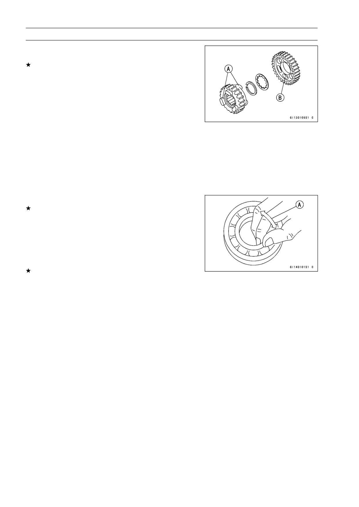
Gear Dog and Gear Dog Hole Damage Inspection
• Visually inspect the gear dogs [A] and gear dog holes [B].
Replace any damaged gears or gears with excessively
worn dogs or dog holes.
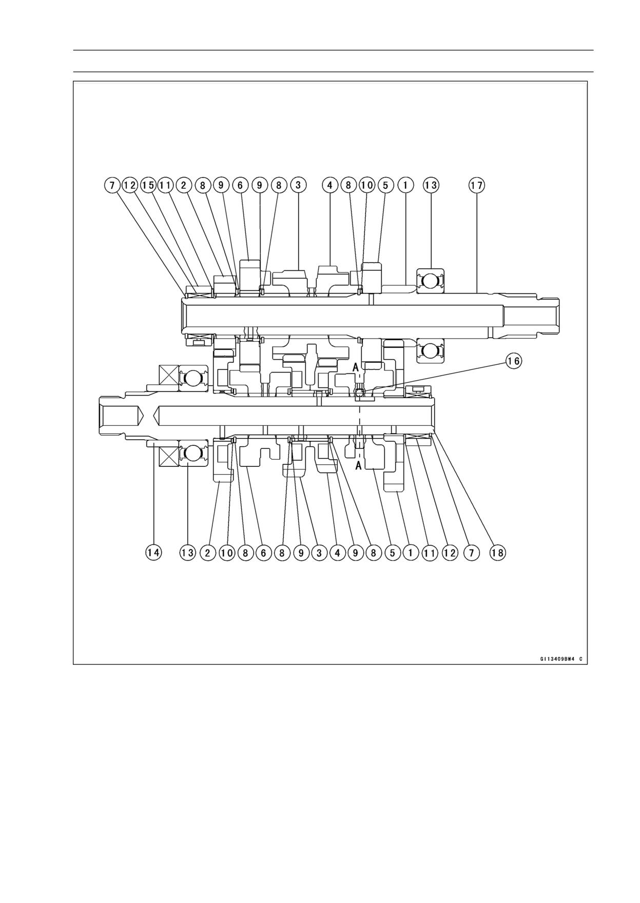
Ball and Needle Bearing Wear Inspection
• Check the following ball bearings: right hand drive shaft,
left hand output shaft, and right hand shift drum.
○Since the ball bearings are made to extremely close toler-
ances, the wear must be judged by feel rather than mea-
surement. Clean each bearing in a high flash-point sol-
vent, dry it (do not spin the bearing while it is dry), and oil
it with engine oil.
○Spin [A] the bearing by hand to check its condition.
If the bearing is noisy, does not spin smoothly, or has any
rough spots, replace it.
• Check the following needle bearing: left hand drive shaft,
and right hand output shaft.
○The rollers in a needle bearing normally wear very little,
and wear is difficult to measure. Instead of measuring,
inspect the bearing for abrasion, color change, or other
damage.
If there is any doubt as to the condition of a needle bear-
ing, replace it.
CRANKSHAFT/TRANSMISSION 9-33
Transmission
1. 1st Gear
10. Washer
2. 2nd Gear
11. Thrust Washer
3. 3rd Gear
12. Needle Bearing
4. 4th Gear
13. Ball Bearing
5. 5th Gear
14. Collar
6. 6th (Top) Gear
15. Bearing Outer Race
7. Circlip
16. Steel Ball
8. Circlip
17. Drive Shaft
9. Toothed Washer
18. Output Shaft
WHEELS/TIRES 10-1
Wheels/Tires
Table of Contents
Exploded View
10-2
Specifications
10-4
Special Tools
10-5
Wheels (Rims)
10-6
Front Wheel Removal
10-6
Front Wheel Installation
10-6
Rear Wheel Removal
10-7
Rear Wheel Installation
10-7
Wheel Inspection
10-9
Axle Inspection
10-9
Balance Inspection
10-10
Balance Adjustment
10-10
Balance Weight Removal
10-10
Balance Weight Installation
10-10
Tires
10-12
Air Pressure Inspection/Adjustment
10-12
Tire Inspection
10-12
Tire Removal
10-12
Tire Installation
10-13
10
Tire Repair
10-15
Hub Bearing
10-16
Hub Bearing Removal
10-16
Hub Bearing Installation
10-16
Hub Bearing Inspection
10-17
Hub Bearing Lubrication
10-17
Speedometer Gear Housing
10-18
Speedometer Gear Housing Disassembly
10-18
Speedometer Gear Housing Assembly
10-18
Speedometer Gear Housing Lubrication
10-19
10-2 WHEELS/TIRES
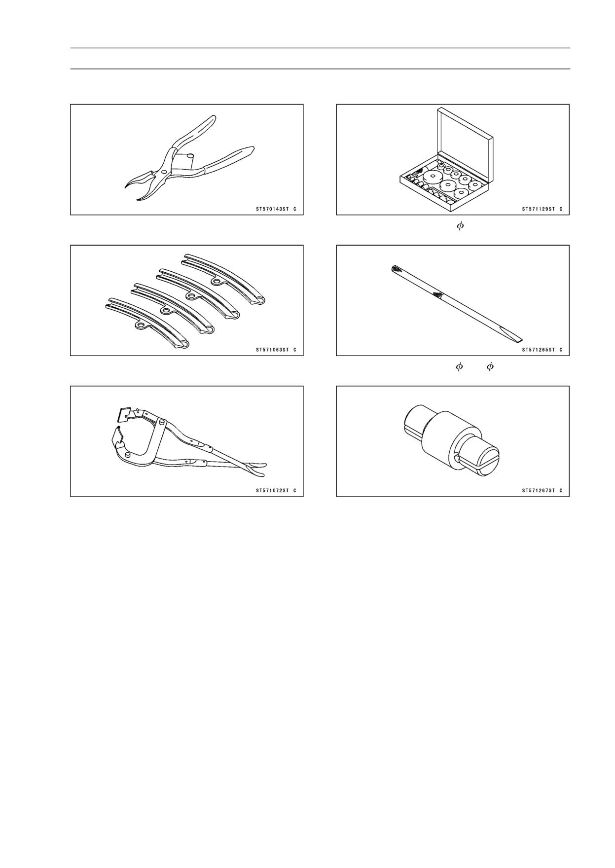
Exploded View
WHEELS/TIRES 10-3
Exploded View
Torque
No.
Fastener
Remarks
N·m
kgf·m
ft·lb
1
Front Axle Nut
88
9.0
65
2
Rear Axle Nut
98
10.0
72
G: Apply grease.
R: Replacement Parts

10-4 WHEELS/TIRES
Specifications
Item
Standard
Service Limit
Wheels (Rims)
Rim Runout:
Axial
TIR 0.5 mm (0.02 in.) or less
TIR 1.0 mm (0.04 in.)
Radial
TIR 0.8 mm (0.03 in.) or less
TIR 1.0 mm (0.04 in.)
Axle Runout/100 mm (3.94 in.)
TIR 0.1 mm (0.004 in.) or less
TIR 0.2 mm (0.008 in.)
Wheel Balance
10 g (0.35 oz.) or less
- - -
Balance Weights
10 g (0.35 oz.), 20 g (0.71 oz.), 30 g
- - -
(1.06 oz.)
Rim Size:
Front
17 M/C × MT2.75
- - -
Rear
17 M/C × MT3.50
- - -
Tires
Air Pressure (when Cold):
Front
Up to 170 kg (375 lb) load: 200 kPa
- - -
(2.00 kgf/cm², 28 psi)
Rear
Up to 170 kg (375 lb) load: 225 kPa
- - -
(2.25 kgf/cm², 32 psi)
Tread Depth:
Front:
BRIDGESTONE
4.6 mm (0.181 in.)
1 mm (0.04 in.)
DUNLOP
4.5 mm (0.177 in.)
IRC
4.2 mm (0.165 in.)
Rear:
BRIDGESTONE
7.0 mm (0.276 in.)
Up to 130 km/h (80 mph):
2 mm (0.08 in.)
DUNLOP
7.4 mm (0.291 in.)
Over 130 km/h (80 mph):
3 mm (0.12 in.)
IRC
6.5 mm (0.255 in.)
Standard Tires:
Make, Type
Size
Front
BRIDGESTONE BATTLAX BT45F
110/70 17 M/C (54 H)
DUNLOP GT 501FG T/L
IRC RX-01F
110/70 17 M/C (54 S)
Rear
BRIDGESTONE BATTLAX BT45R
130/70 17 M/C (62 H)
DUNLOP GT501 T/L
IRC RX-01R
130/70 17 M/C (62 S)
WARNING
Some replacement tires may adversely affect handling and cause an accident resulting in
serious injury or death. To ensure proper handling and stability, use only the recommended
standard tires for replacement, inflated to the standard pressure.
WHEELS/TIRES 10-5
Special Tools
Inside Circlip Pliers:
Bearing Driver Set:
57001-143
57001-1129
Rim Protector:
Bearing Remover Shaft,
9:
57001-1063
57001-1265
Bead Breaker Assembly:
Bearing Remover Head,
15 ×
17:
57001-1072
57001-1267
10-6 WHEELS/TIRES
Wheels (Rims)
Front Wheel Removal
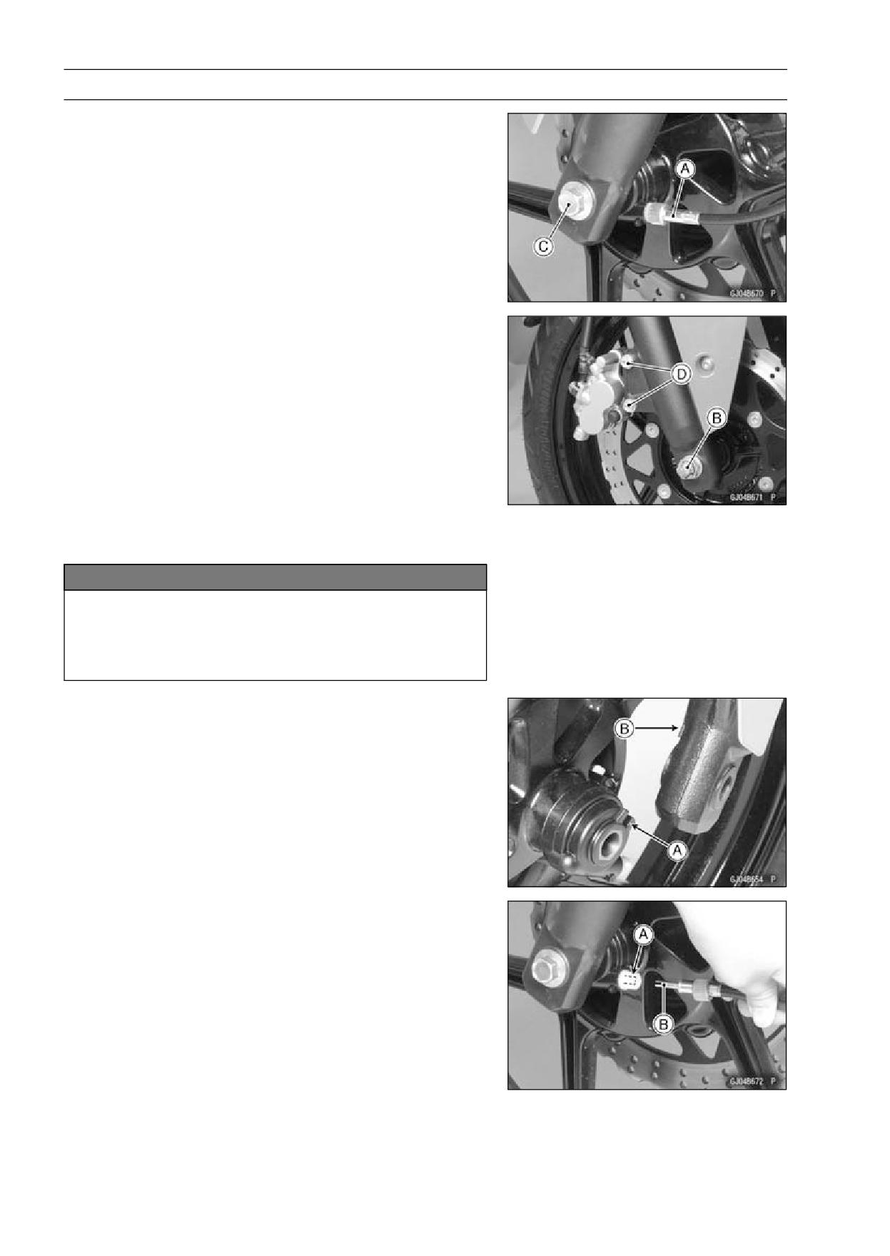
• Remove:
Speedometer Cable Lower End [A]
Axle Nut Cotter Pin [B]
Axle (Loosen) [C]
Front Caliper Mounting Bolts [D]
• Using a jack, raise the front wheel off the ground.
• Pull the axle and remove the front wheel.
NOTICE
Do not lay the wheel on the ground with the disc
facing down. This can damage or warp the disc.
Place blocks under the wheel so that the disc does
not touch the ground.
Front Wheel Installation
• Apply a high-temperature grease to the grease seal lips.
• Install the speedometer gear housing to the front wheel.
• Install the front wheel so that the speedometer gear hous-
ing stop [A] fit into the fork leg stops [B].
• Install the speedometer cable so that the drive notch [B]
of it fits into the projection [A] of the speedometer gear in
the housing.
• Tighten the front axle nut with the specified torque.
Torque - Front Axle Nut: 88 N·m (9.0 kgf·m, 65 ft·lb)
WHEELS/TIRES 10-7
Wheels (Rims)
• Check the front brake effectiveness (see Brake Operation
Inspection in the Periodic Maintenance chapter).
WARNING
After servicing, it takes several applications of the
brake lever before the brake pads contact the disc,
which could result in increased stopping distance
and cause an accident resulting in injury or death.
Do not attempt to ride the motorcycle until a firm
brake lever is obtained by pumping the lever until
the pads are against the disc.
Rear Wheel Removal
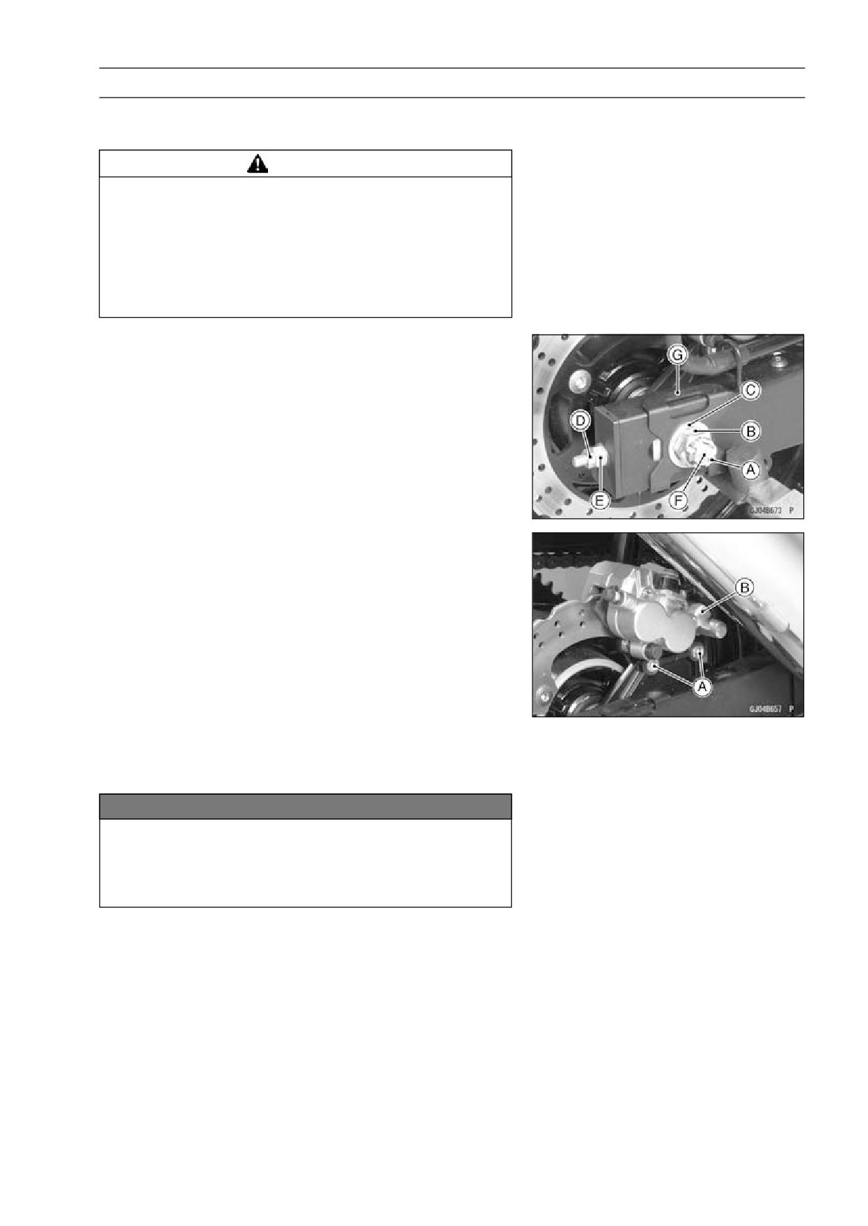
• Remove:
Axle Nut Cotter Pin [A]
Axle Nut [B] and Washer [C]
Chain Locknuts (Loosen) [D] and Adjusting Nuts [E]
Axle [F]
Alignment Indicators [G]
• Remove:
Rear Caliper Mounting Bolts [A]
Rear Caliper [B]
• Raise the rear wheel off the ground with the stand.
• Free the drive chain from the rear sprocket, and remove
the rear wheel.
NOTICE
Do not lay the wheel on the ground with the disc
facing down. This can damage or warp the disc.
Place blocks under the wheel so that the disc does
not touch the ground.
Rear Wheel Installation
• Apply a high temperature grease to the grease seal lips
and coupling, wheel sliding portions.
10-8 WHEELS/TIRES
Wheels (Rims)
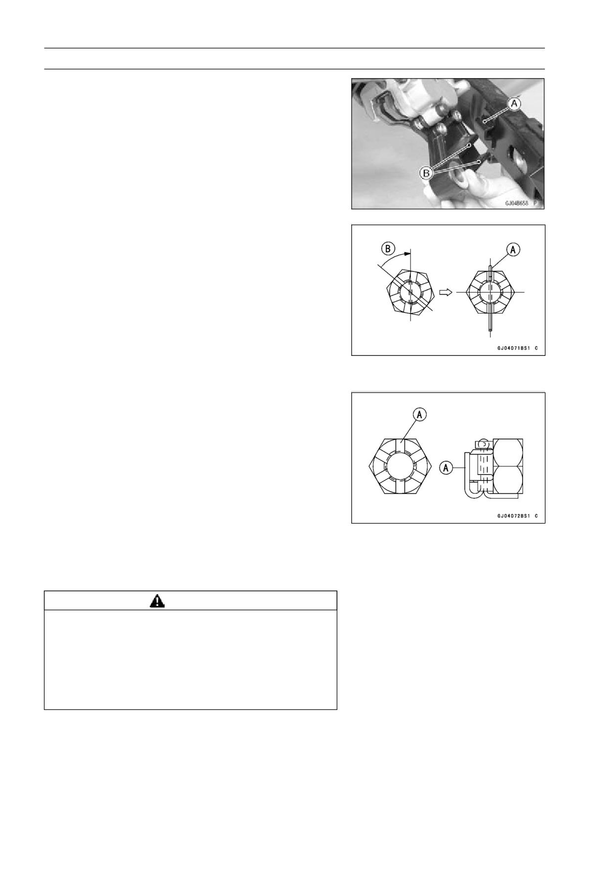
• Fit the swingarm stop [A] into the caliper holder stops [B].
• Install:
Alignment Indicators
Axle
Chain Adjusting Nuts and Locknuts
Axle Nut and Washer
Axle Nut Cotter Pin
Torque - Rear Axle Nut: 98 N·m (10.0 kgf·m, 72 ft·lb)
NOTE
○Insert the axle from the right side of the wheel, and
tighten the axle nut.
• Install a new cotter pin.
NOTE
○When inserting the cotter pin, if the slots in the nut do
not align with the cotter pin hole in the axle, tighten the
nut clockwise [B] up to next alignment.
○It should be within 30 degrees.
○Loosen once and tighten again when the slot goes past
the nearest hole.
• Bend the cotter pin [A] over the nut.
• Adjust the drive chain slack (see Drive Chain Slack Ad-
justment in the Periodic Maintenance chapter).
• Check the rear brake (see Brake Operation Inspection in
the Periodic Maintenance chapter).
WARNING
After servicing, it takes several applications of the
brake pedal before the brake pads contact the disc,
which could result in increased stopping distance
and cause an accident resulting in injury or death.
Do not attempt to ride the motorcycle until a firm
brake pedal is obtained by pumping the pedal until
the pads are against the disc.
WHEELS/TIRES 10-9
Wheels (Rims)
Wheel Inspection
• Raise the front/rear wheel off the ground.
• Spin the wheel lightly, and check for roughness or binding.
If the roughness or binding is found, replace the hub bear-
ings.
• Inspect the wheel for small cracks, dents, bending, or
warp.
If there is any damage to the wheel, replace the wheel.
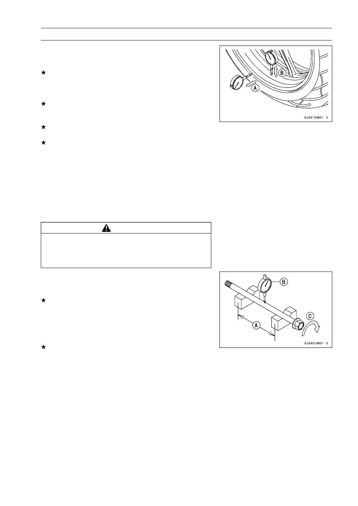
• Measure the rim runout, radial [B] and axial [A], with a dial
gauge.
If the rim runout exceeds the service limit, check the hub
bearings.
If the problem is not due to the bearings, replace the
wheel.
Rim Runout (with tire installed)
Standard:
Axial
TIR 0.5 mm (0.02 in.) or less
Radial
TIR 0.8 mm (0.03 in.) or less
Service Limit:
Axial
TIR 1.0 mm (0.04 in.)
Radial
TIR 1.0 mm (0.04 in.)
WARNING
Damaged wheel parts may fail and cause an acci-
dent resulting in serious injury or death. Never at-
tempt to repair a damaged wheel part. If the wheel
part is damaged, it must be replaced with a new one.
Axle Inspection
• Remove the front and rear axles.
• Visually inspect the front and rear axle for damages.
If the axle is damaged or bent, replace it.
• Place the axle in V blocks that are 100 mm (3.94 in.) [A]
apart, and set a dial gauge [B] on the axle at a point
halfway between the blocks. Turn [C] the axle to mea-
sure the runout. The difference between the highest and
lowest dial readings is the amount of runout.
If the axle runout exceeds the service limit, replace the
axle.
Axle Runout/100 mm (3.94 in.)
Standard:
TIR 0.1 mm (0.004 in.) or less
Service Limit: TIR 0.2 mm (0.008 in.)
10-10 WHEELS/TIRES
Wheels (Rims)
Balance Inspection
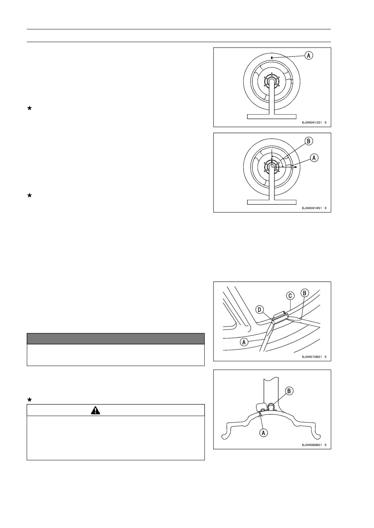
• Remove the wheel.
• Support the wheel so that it can be spun freely.
• Spin the wheel lightly, and mark [A] the wheel at the top
when the wheel stops.
○Repeat this procedure several times. If the wheel stops
of its own accord in various positions, it is well balanced.
If the wheel always stops in one position, adjust the wheel
balance.
Balance Adjustment
• If the wheel always stops in one position, provisionally
attach a balance weight [A] on the rim at the marking using
adhesive tape.
• Rotate the wheel 1/4 turn [B], and see whether or not the
wheel stops in this position. If it does, the correct balance
weight is being used.
If the wheel rotates and the weight goes up, replace the
weight with the next heavier size. If the wheel rotates and
the weight goes down, replace the weight with the next
lighter size. Repeat these steps until the wheel remains
at rest after being rotated 1/4 turn.
• Rotate the wheel another 1/4 turn and then another 1/4
turn to see if the wheel is correctly balanced.
• Repeat the entire procedure as many times as necessary
to achieve correct wheel balance.
• Permanently install the balance weight.
Balance Weight Removal
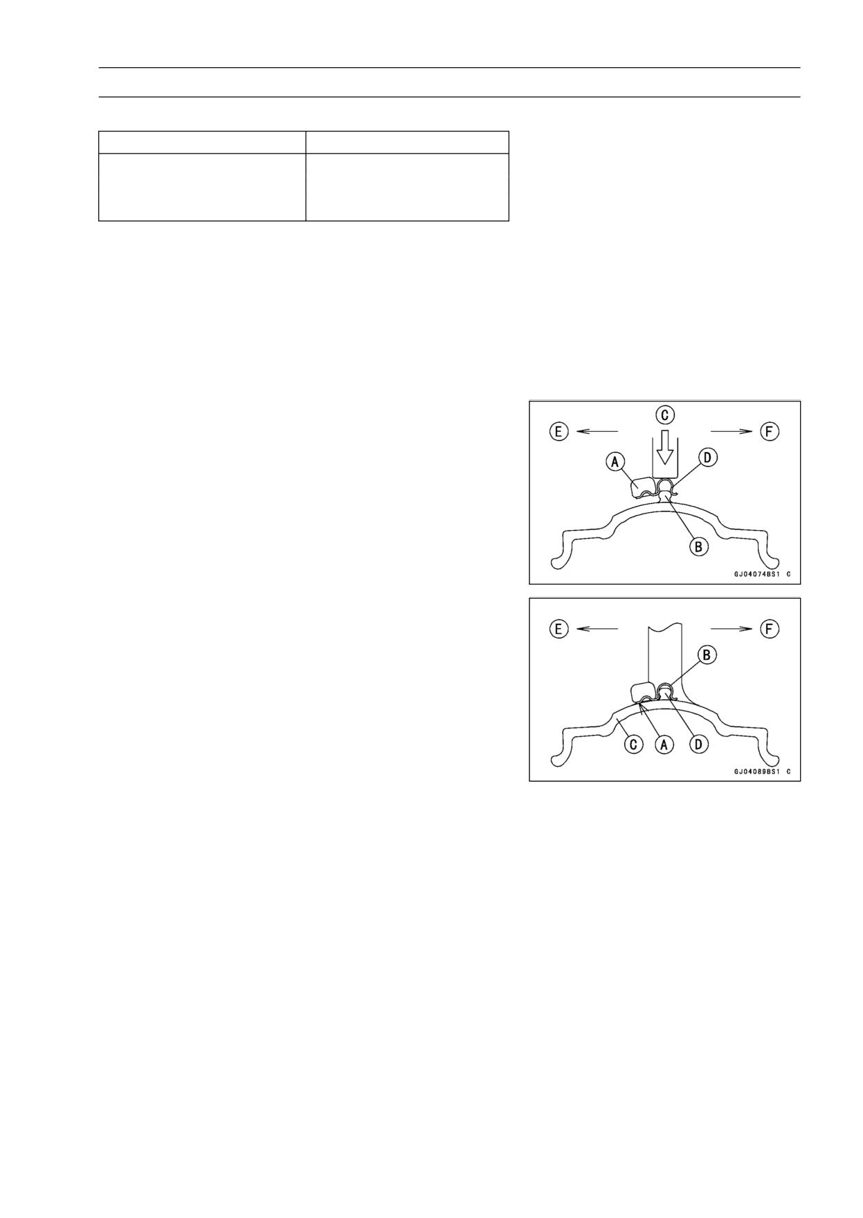
• Insert a standard tip screwdrivers [A] [B] between the rib
[C] and weight [D] as shown.
• Pry the balance weight with two screwdrivers and remove
the balance weight.
• Discard the used balance weight.
NOTICE
Do not tap the screwdrivers. The rim could be dam-
aged.
Balance Weight Installation
• Check if the weight portion has any play on the blade [A]
and clip [B].
If it does, discard it.
WARNING
Unbalanced wheels can create an unsafe riding
condition. If the balance weight has any play on
the rib of the rim, the blade and/or clip have been
stretched. Replace the loose balance weight. Do
not reuse used balance weight.
WHEELS/TIRES 10-11
Wheels (Rims)
Balance Weight
Part Number
Weight
41075-0007
10 g (0.35 oz.)
41075-0008
20 g (0.71 oz.)
41075-0009
30 g (1.06 oz.)
NOTE
○Balance weights are available from Kawasaki dealers in
10, 20, and 30 gram (0.35 oz., 0.71 oz., and 1.06 oz.)
sizes. An imbalance of less than 10 grams (0.35 oz.)
will not usually affect running stability.
○Do not use four or more balance weight (more than 90
gram). If the wheel requires an excess balance weight,
disassemble the wheel to find the cause.
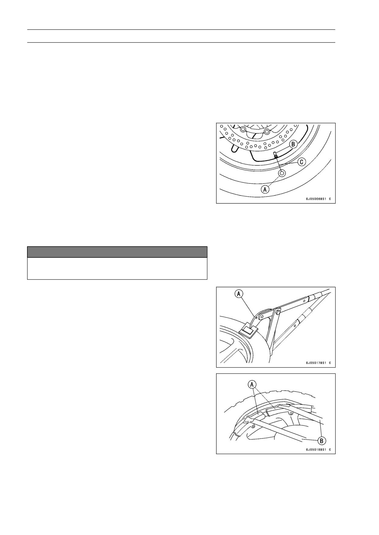
• Slip the balance weight [A] on to the rib [B], by pushing or
lightly hammering [C] the clip [D].
Left Side [E]
Right Side [F]
• Be sure to install the balance weight.
○Check that the blade [A] and clip [B] are fully seated on
the rim [C] and that the clip is hooked over the rib [D].
Left Side [E]
Right Side [F]
10-12 WHEELS/TIRES
Tires
Air Pressure Inspection/Adjustment
• Refer to Air Pressure Inspection in the Periodic Mainte-
nance chapter (see Air Pressure Inspection in the Peri-
odic Maintenance chapter).
Tire Inspection
• Refer to Wheels/Tires Damage Inspection in the Periodic
Maintenance chapter (see Wheels/Tires Damage Inspec-
tion in the Periodic Maintenance chapter).
Tire Removal
• Remove:
Wheel (see Wheel Removal)
Disc
Valve Core (let out the air)
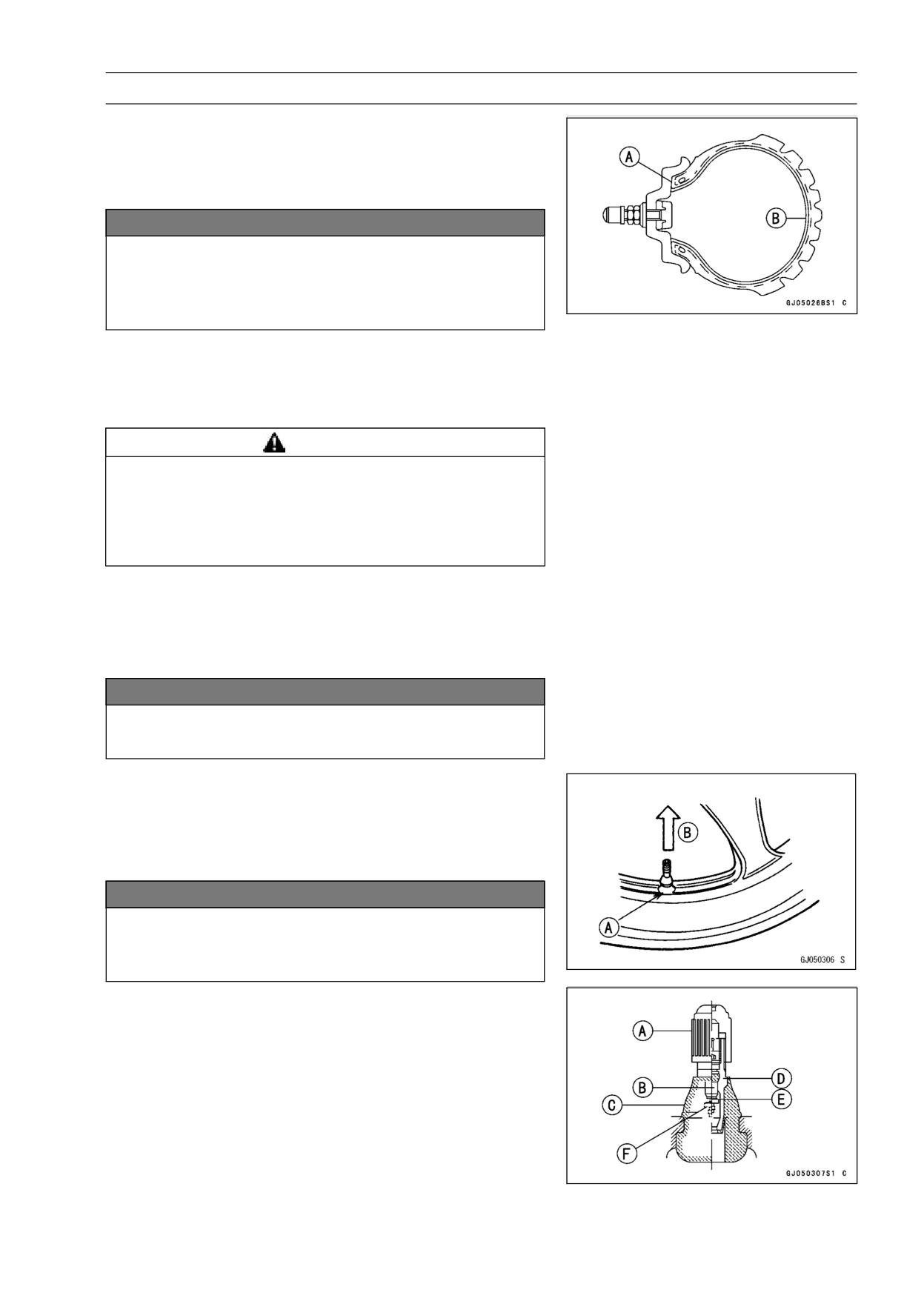
• To maintain wheel balance, mark the air valve position on
the tire with chalk so that the tire can be reinstalled in the
same position.
Chalk Mark or Yellow Mark [A]
Air Valve [B]
Align [C]
• Lubricate the tire beads and rim flanges on both sides with
a soap and water solution or rubber lubricant. This helps
the tire beads slip off the rim flanges.
NOTICE
Never lubricate with engine oil or petroleum distil-
lates because they will deteriorate the tire.
• Break the beads away from both sides of the rim with the
bead breaker [A].
Special Tool - Bead Breaker Assembly: 57001-1072
• Step on the side of the tire opposite the valve stem and
start prying the tire off the rim near the air valve with tire
irons.
Special Tools - Rim Protector: 57001-1063 [A]
Bead Breaker Assembly: 57001-1072 [B]
WHEELS/TIRES 10-13
Tires
NOTE
○For easier removal, always position the tire bead oppo-
site the valve stem in the rim well, and pry the tire bead
a little at a time.
NOTICE
Be careful not to scratch the inner liner and air seal-
ing surfaces of the rim and tire with the tire irons. A
scratched inner liner [B] or sealing surface [A] may
allow air to leak.
• After removing the bead on one side, remove the other
bead from the same manner.
• Remove the tire from the rim.
Tire Installation
WARNING
Some replacement tires may adversely affect han-
dling and cause an accident resulting in serious in-
jury or death. To ensure proper handling and sta-
bility, use only the recommended standard tires for
replacement, inflated to the standard pressure.
• Inspect the rim and tire, and replace them if necessary.
• Clean the sealing surfaces of the rim and tire, and smooth
the sealing surfaces of the rim with a fine emery cloth if
necessary.
• Remove the air valve and discard it.
NOTICE
Replace the air valve whenever the tire is replaced.
Do not reuse the air valve.
• Install a new valve in the rim.
○Remove the valve cap, lubricate the stem seal [A] with a
soap and water solution or rubber lubricant, and pull [B]
the valve stem through the rim from the inside out until it
snaps into place.
NOTICE
Do not use engine oil or petroleum distillates to lu-
bricate the stem because they will deteriorate the
rubber.
○The air valve is shown in the figure.
[A] Valve Cap
[B] Valve Core
[C] Stem Seal
[D] Valve Stem
[E] Valve Seat
[F] Valve Opened
10-14 WHEELS/TIRES
Tires
• Apply a soap and water solution, or rubber lubricant to the
rim flange and tire beads.
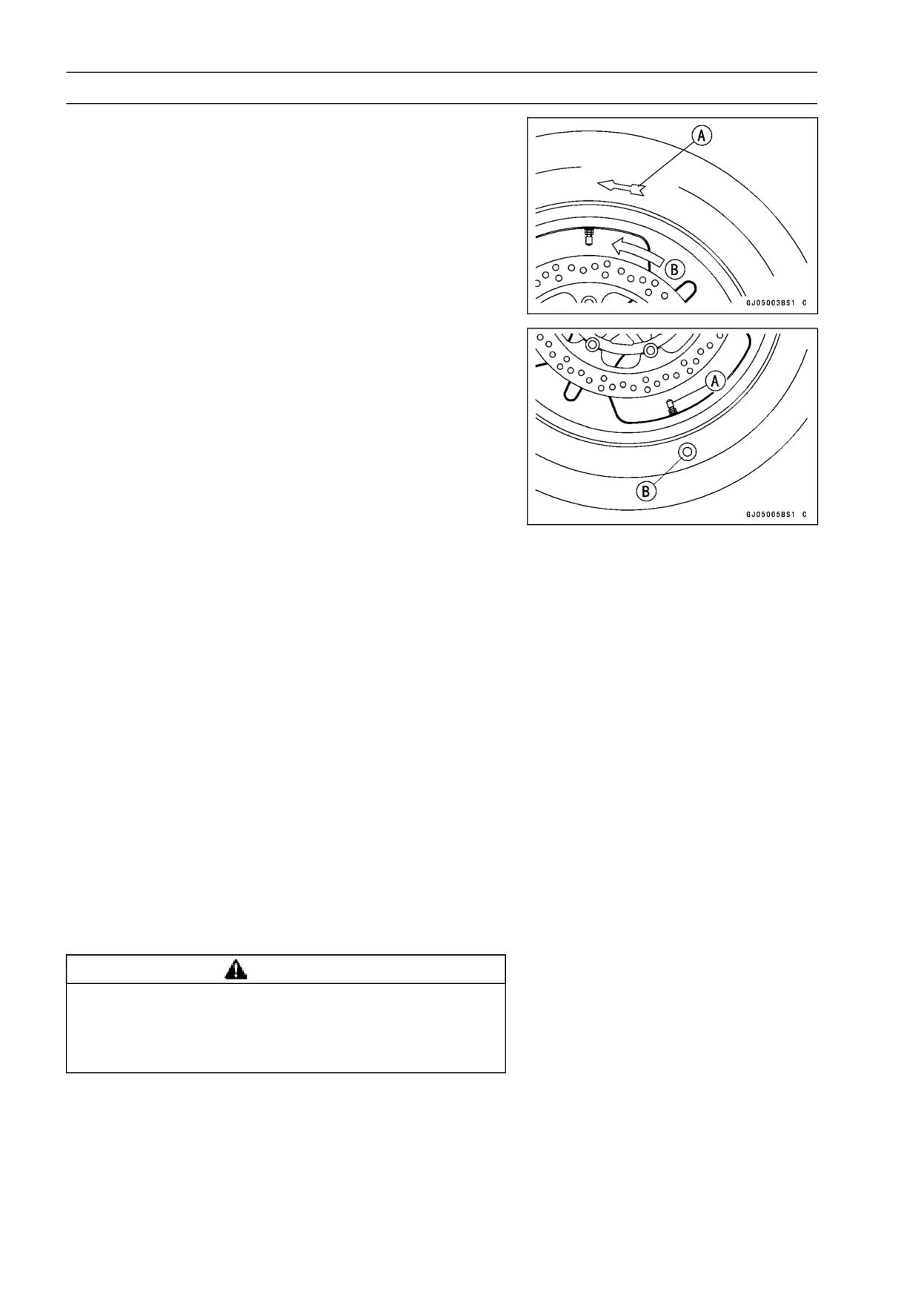
• Check the tire rotation mark on the front and rear tires and
install them on the rim accordingly.
Tire Rotation Mark [A]
Rotating Direction [B]
• Position the tire on the rim so that the air valve [A] align
with the tire balance mark [B] (the chalk mark made during
removal, or the yellow paint mark on a new tire).
• By hand, slide as much as possible of the lower side of the
tire bead over the rim flange, starting at the side opposite
the valve stem.
• Fit the rim protectors and tire irons to install the remaining
part of the tire bead which cannot be installed by hand.
For easy tire installation, position the parts of the bead
which is already over the rim flange in the rim well.
NOTE
○To prevent rim damage, be sure to place the rim protec-
tors at any place the tire irons are applied.
• Install the other side of the tire bead onto the rim in the
same manner.
• Lubricate the tire beads and rim flanges with a soap and
water solution or rubber lubricant to help seat the tire
beads in the sealing surfaces of the rim while inflating the
tire.
• Center the rim in the tire beads, and inflate the tire with
compressed air until the tire beads seat in the sealing
surfaces.
WARNING
Overinflating a tire can cause it to explode, causing
serious injury or death. Be sure to install the valve
core whenever inflating the tire, and do not inflate
the tire to more than 400 kPa (4.0 kgf/cm², 57 psi).
WHEELS/TIRES 10-15
Tires
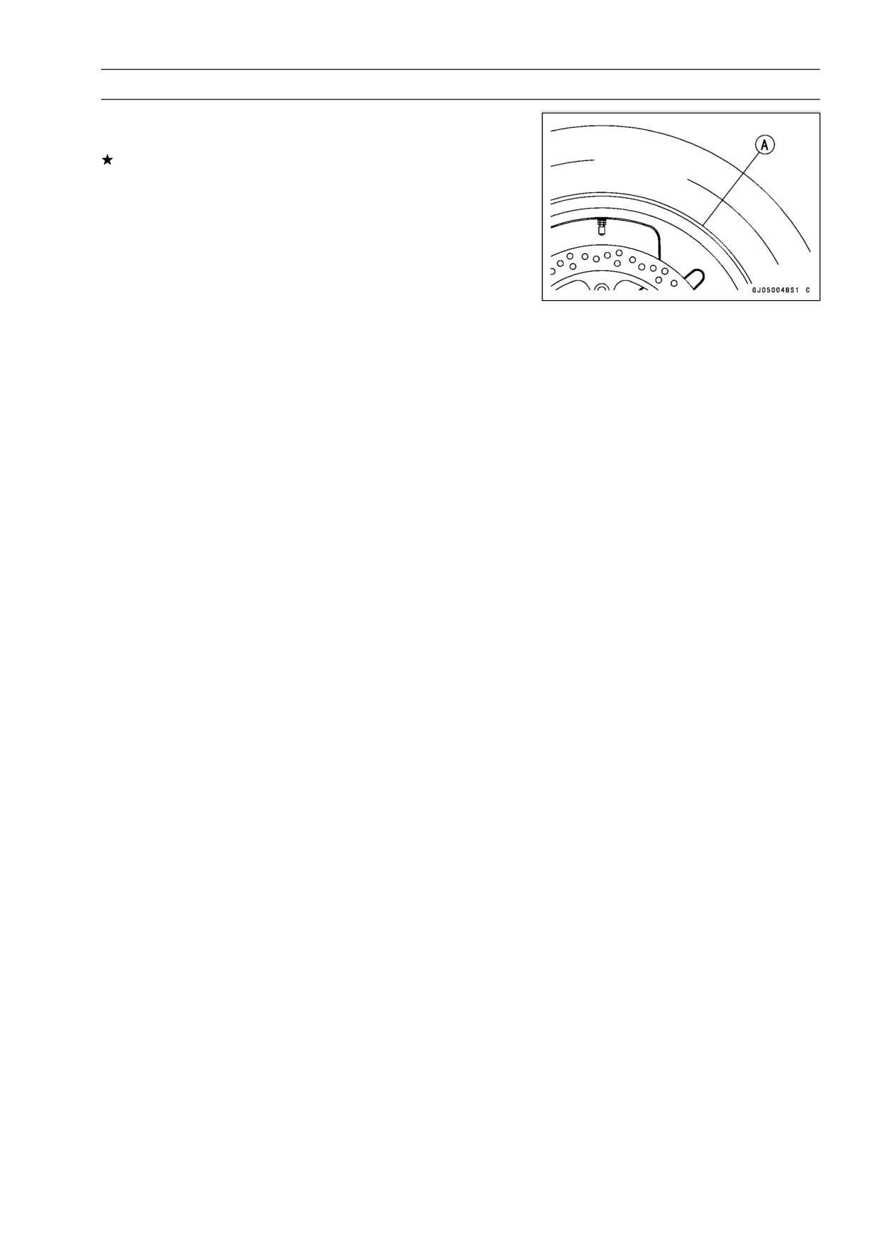
• Check to see that the rim lines [A] on both sides of the tire
sidewalls are parallel with the rim flanges.
If the rim flanges and tire sidewall rim lines are not parallel,
remove the valve core.
• Lubricate the rim flanges and tire beads.
• Install the valve core and inflate the tire again.
• After the tire beads seat in the rim flanges, check for air
leakage.
○Inflate the tire slightly above standard inflation.
○Use a soap and water solution or submerge the tire, and
check for bubbles that would indicate leakage.
• Adjust the air pressure to the specified pressure (see Air
Pressure Inspection in the Periodic Maintenance chap-
ter).
• Install the brake disc(s) so that the marked side faces out
(see Brake Disc Installation in the Brakes chapter).
• Adjust the wheel balance (see Balance Adjustment).
Tire Repair
Currently two types of repair for tubeless tires have come
into wide use. One type is called a temporary (external) re-
pair which can be carried out without removing the tire from
the rim, and the other type is called permanent (internal)
repair which requires tire removal. It is generally under-
stood that higher running durability is obtained by perma-
nent (internal) repairs than by temporary (external) ones.
Also, permanent (internal) repairs have the advantage of
permitting a thorough examination for secondary damage
not visible from external inspection of the tire. For these
reasons, Kawasaki does not recommend temporary (exter-
nal) repair. Only appropriate permanent (internal) repairs
are recommended. Repair methods may vary slightly from
make to make. Follow the repair methods indicated by the
manufacturer of the repair tools and materials so that safe
results can be obtained.
10-16 WHEELS/TIRES
Hub Bearing
Hub Bearing Removal
• Remove the wheel, and take out the following.
Collars
Speedometer Gear Drive (out of front hub)
Coupling (out of rear hub)
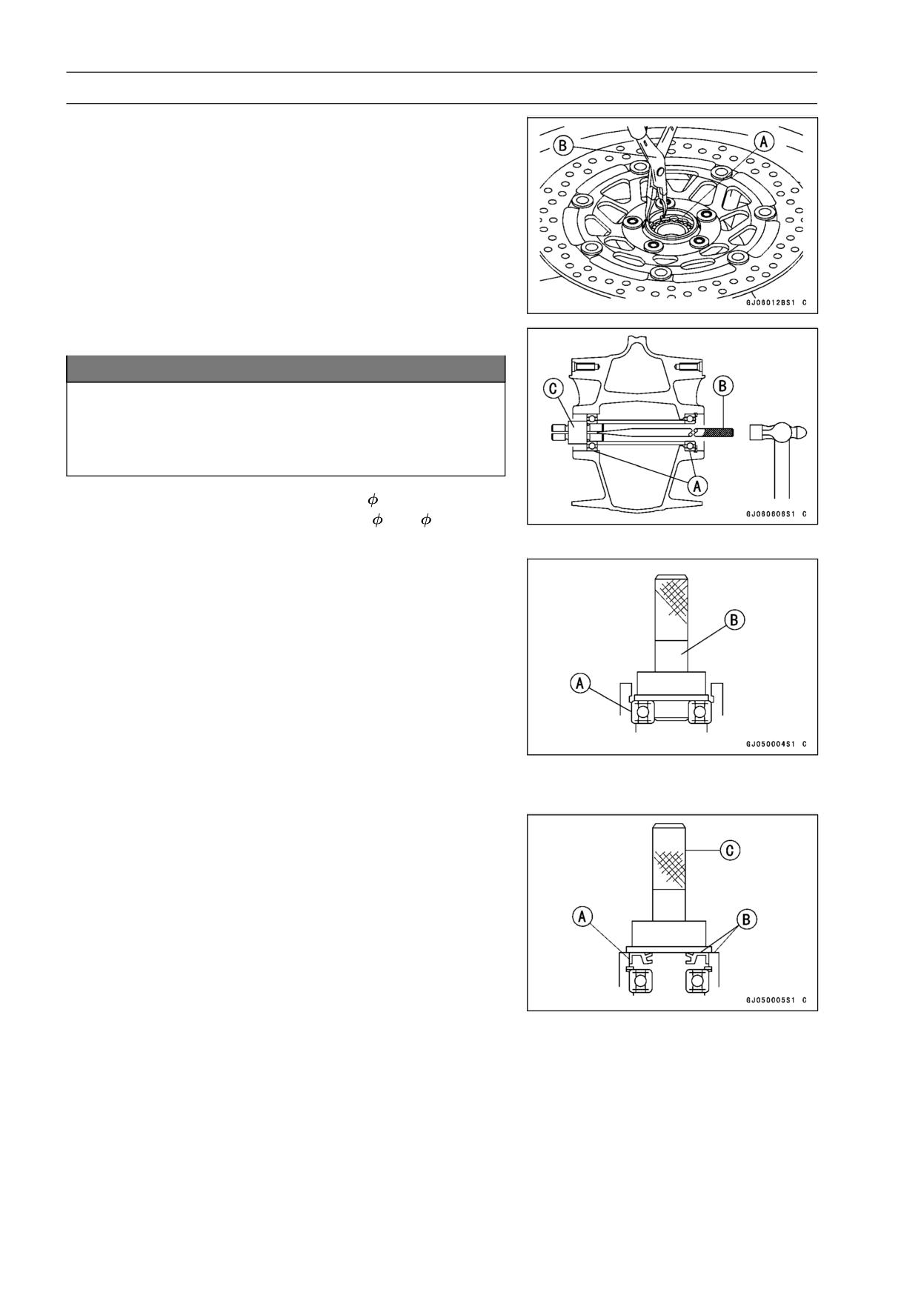
Grease Seals
Circlips [A]
Special Tool - Inside Circlip Pliers: 57001-143 [B]
• Use the bearing remover to remove the hub bearings [A].
NOTICE
Do not lay the wheel on the ground with the disc
facing down. This can damage or warp the disc.
Place blocks under the wheel so that the disc does
not touch the ground.
Special Tools - Bearing Remover Shaft,
9: 57001-1265 [B]
Bearing Remover Head,
15 ×
17: 57001
-1267 [C]
Hub Bearing Installation
• Before installing the hub bearings, blow any dirt or foreign
particles out of the hub with compressed air to prevent
contamination of the bearings.
• Replace the bearings with new ones.
NOTE
○Install the bearings so that the marked side faces out.
• Install the bearings by using the bearing driver set which
does not contact the bearing inner race.
• Press in each bearing [A] until they are bottomed.
Special Tool - Bearing Driver Set: 57001-1129 [B]
• Replace the circlips with new ones.
Special Tool - Inside Circlip Pliers: 57001-143
• Replace the grease seals with new ones.
• Press in the grease seals [A] so that the seal surface is
flush [B] with the end of the hole.
○Apply high-temperature grease to the grease seal lips.
Special Tool - Bearing Driver Set: 57001-1129 [C]
WHEELS/TIRES 10-17
Hub Bearing
Hub Bearing Inspection
Since the hub bearings are made to extremely close tol-
erances, the clearance can not normally be measured.
NOTE
○Do not remove any bearings for inspection. If any bear-
ings are removed, they will need to be replaced with
new ones.
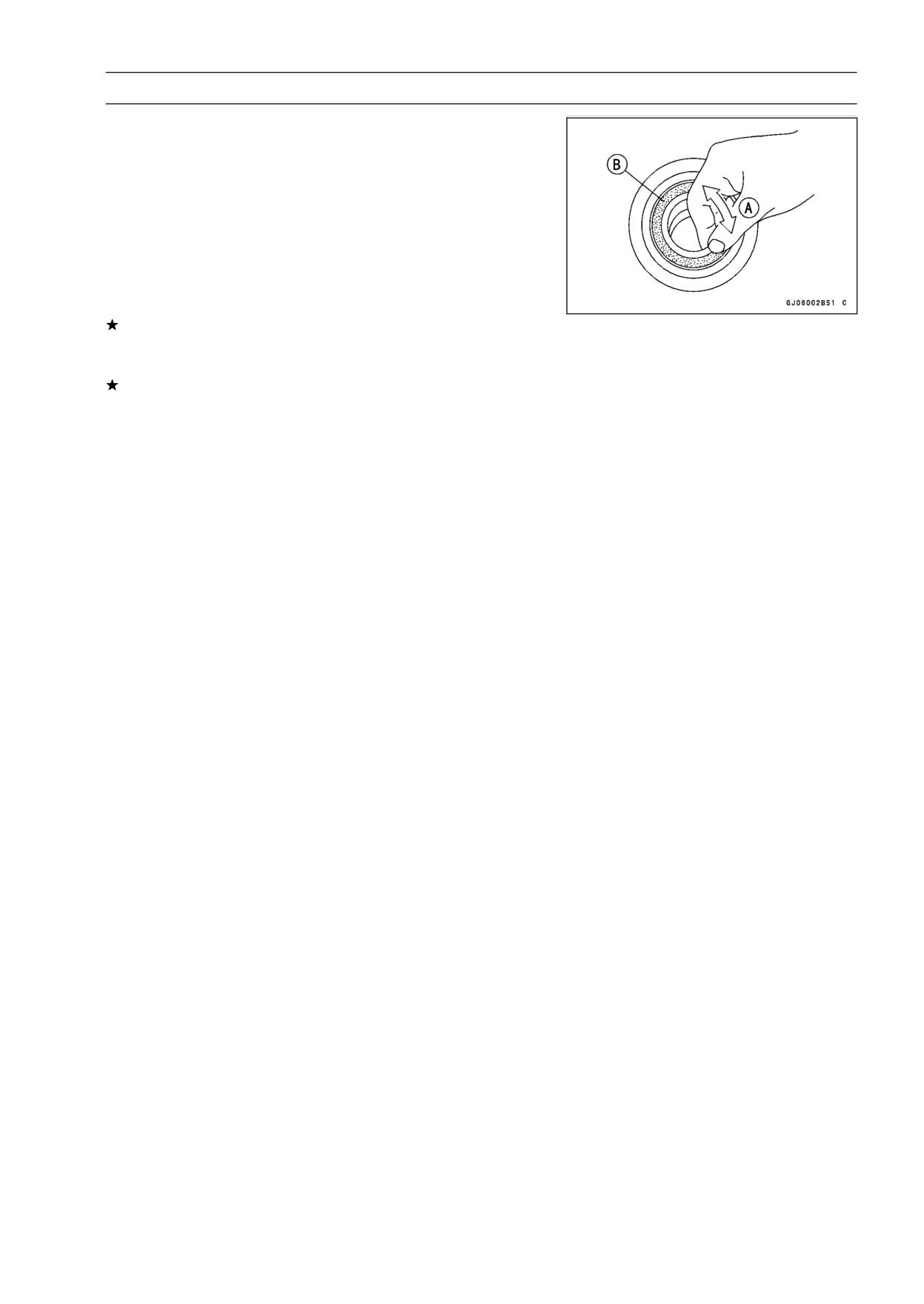
• Turn each bearing in the hub back and forth [A] while
checking for plays, roughness, or binding.
If bearing play, roughness, or binding is found, replace
the bearing.
• Examine the bearing seal [B] for tears or leakage.
If the seal is torn or is leaking, replace the bearing.
Hub Bearing Lubrication
NOTE
○Since the hub bearings are packed with grease and
sealed, lubrication is not required.
10-18 WHEELS/TIRES
Speedometer Gear Housing
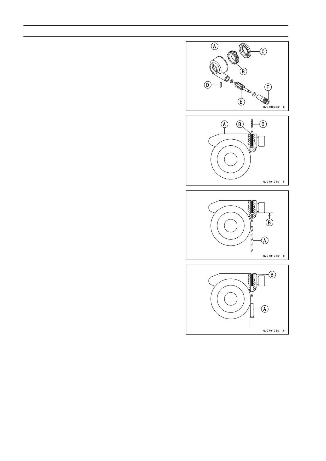
Speedometer Gear Housing Disassembly
• Pull the speedometer gear housing [A] off the front wheel.
• Pull out the grease seal [C] using a hook.
• Pull out the speedometer gear [B].
• If the speedometer cable housing [F] or speedometer pin-
ion [E] needs to be removed, work in accordance with fol-
lowing procedures.
Pin [D]
• First drill the housing [A] through the spring pin [B] using
a 1.0 ∼ 1.5 mm drill bit [C].
• Drill the housing from the under side to the pin end [B]
using 3.0 ∼ 3.5 mm drill bit [A].
• Using a 3 mm (0.12 in.) rod [A], tap out the pin [B], and
then pull out the speedometer cable bushing, speedome-
ter pinion and washers.
NOTE
○It is recommended that the assembly be replaced rather
than attempting to repair the components.
Speedometer Gear Housing Assembly
• When assembling the speedometer gear housing, be
careful of the following items.
○After inserting a new pin, stake the housing hole to secure
the pin in place.
○Replace the grease seal with a new one. Apply a little
grease to the seal. Install it using a press or a suitable
driver so that the face of the seal is level with the surface
of the housing.
○Regrease the speedometer gear.
○Install the speedometer gear housing so that it fits in the
speedometer gear drive notches.
WHEELS/TIRES 10-19
Speedometer Gear Housing
Speedometer Gear Housing Lubrication
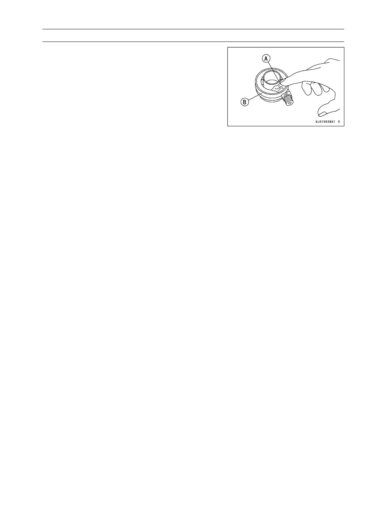
• Clean and grease [A] the speedometer gear housing [B].
FINAL DRIVE 11-1
Final Drive
Table of Contents
Exploded View
11-2
Specifications
11-4
Special Tool
11-5
Drive Chain
11-6
Drive Chain Slack Inspection
11-6
Drive Chain Slack Adjustment
11-6
Wheel Alignment Inspection/Adjustment
11-6
Drive Chain Wear Inspection
11-6
Drive Chain Lubrication
11-6
Drive Chain Removal
11-6
Drive Chain Installation
11-7
Drive Chain
11-8
Drive Chain Replacement
11-8
Sprocket, Coupling
11-11
Engine Sprocket Removal
11-11
Engine Sprocket Installation
11-11
Rear Sprocket Removal
11-12
Rear Sprocket Installation
11-12
Coupling Installation
11-12
Coupling Bearing Removal
11-12
Coupling Bearing Installation
11-13
Coupling Bearing Inspection
11-13
11
Coupling Bearing Lubrication
11-13
Coupling Damper Inspection
11-14
Grease Seal Inspection and Lubrication
11-14
Sprocket Wear Inspection
11-14
Rear Sprocket Warp Inspection
11-14
11-2 FINAL DRIVE
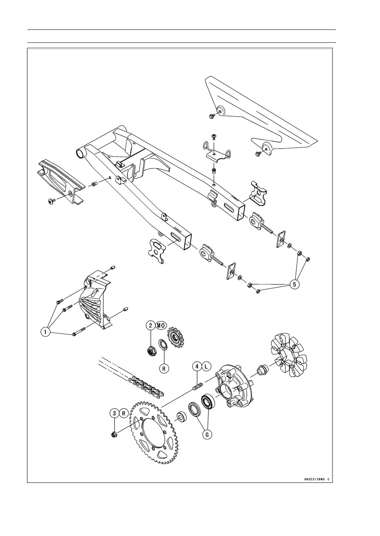
Exploded View
FINAL DRIVE 11-3
Exploded View
Torque
No.
Fastener
Remarks
N·m
kgf·m
ft·lb
1
Engine Sprocket Cover Bolts
9.8
1.0
87 in·lb
2
Engine Sprocket Nut
127
13
94
MO
3
Rear Sprocket Nuts
59
6.0
44
R
4
Rear Sprocket Studs
-
-
-
L
5. Chain Adjusting Nuts and Locknuts
G: Apply grease.
L: Apply a non-permanent locking agent.
MO: Apply molybdenum disulfide oil solution. (mixture of engine oil and molybdenum disulfide grease
in a weight ratio 10 : 1).
R: Replacement Parts
11-4 FINAL DRIVE
Specifications
Item
Standard
Service Limit
Drive Chain
EX250J8 ∼ JA:
Make
ENUMA
- - -
Type
EK520SR-O2
- - -
Link
106 Links
- - -
EX250JB ∼ JC:
Make
DAIDO
- - -
Type
DID 520VP2-T
- - -
Link
106 Links
- - -
Sprockets
Rear Sprocket Warp
TIR 0.4 mm (0.016 in.) or less
TIR 0.5 mm (0.02 in.)
FINAL DRIVE 11-5
Special Tool
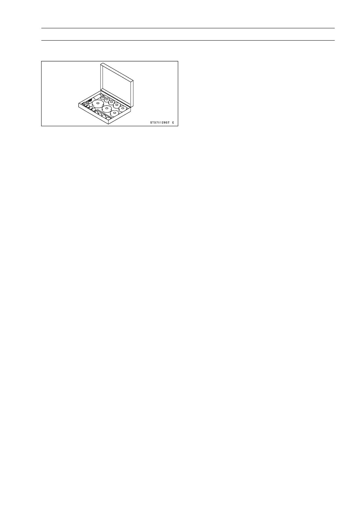
Bearing Driver Set:
57001-1129
11-6 FINAL DRIVE
Drive Chain
Drive Chain Slack Inspection
• Refer to Drive Chain Slack Inspection in the Periodic
Maintenance chapter (see Drive Chain Slack Inspection
in the Periodic Maintenance chapter).
Drive Chain Slack Adjustment
• Refer to Drive Chain Slack Inspection in the Periodic
Maintenance chapter (see Drive Chain Slack Inspection
in the Periodic Maintenance chapter).
Wheel Alignment Inspection/Adjustment
• Refer to Wheel Alignment Inspection in the Periodic Main-
tenance chapter (see Wheel Alignment Inspection in the
Periodic Maintenance chapter).
Drive Chain Wear Inspection
• Refer to Drive Chain Wear Inspection in the Periodic
Maintenance chapter (see Drive Chain Wear Inspection
in the Periodic Maintenance chapter).
Drive Chain Lubrication
• Refer to Drive Chain Lubrication Condition in the Periodic
Maintenance chapter (see Drive Chain Lubrication Con-
dition in the Periodic Maintenance chapter).
Drive Chain Removal
• Remove:
Engine Sprocket Cover
Drive Chain Cover
Rear Shock Absorber (see Rear Shock Absorber Re-
moval in the Suspension chapter)
Swingarm Pivot Shaft (see Swingarm Removal in the
Suspension chapter)
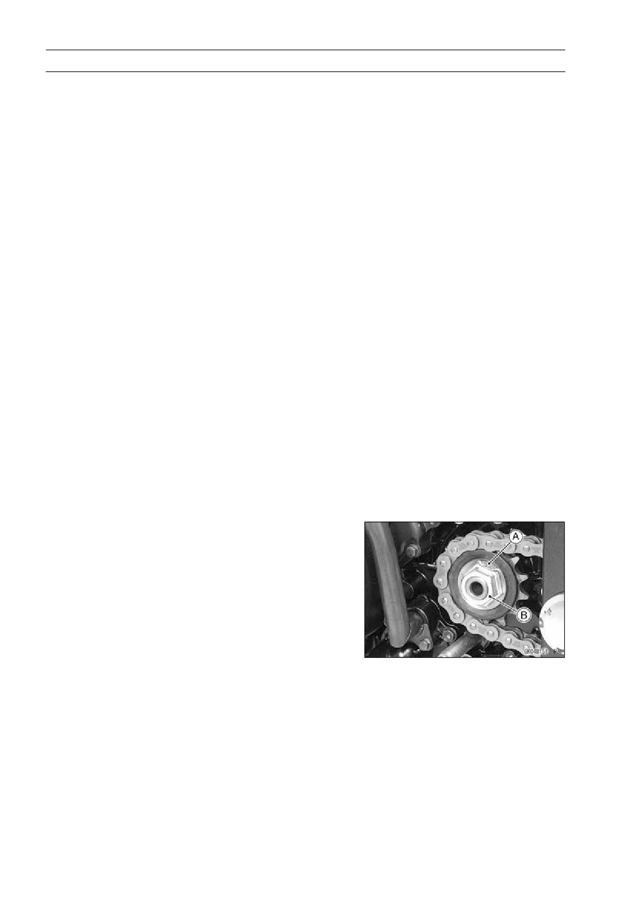
• Flatten out the bended washer [A].
• Remove the engine sprocket nut [B] and washer.
NOTE
○When loosening the engine sprocket nut, hold the rear
brake on.
FINAL DRIVE 11-7
Drive Chain
• Raise the rear wheel off the ground.
• Remove the axle cotter pin, and loosen the rear axle nut.
• Loosen the both chain adjuster locknut to loosen the drive
chain.
• Remove the drive chain from the rear sprocket toward the
right.
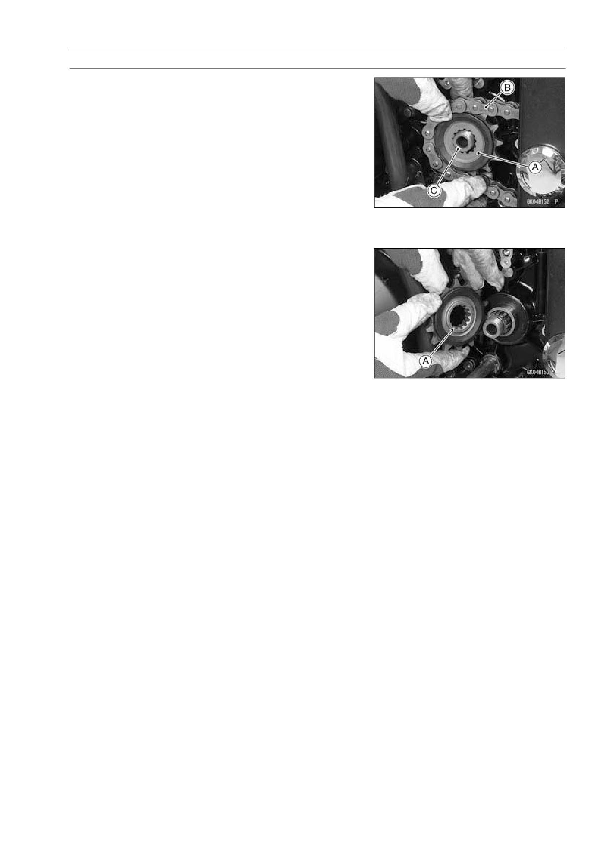
• Pull the engine sprocket [A] with drive chain [B] off the
output shaft [C].
• Disengage the drive chain from the engine sprocket.
NOTE
○The swingarm may be moved with the rear wheel left
installed on it.
Drive Chain Installation
• Replace the sprocket washer and axle cotter pin.
• Install the engine sprocket onto the shaft the protruding
side [A] of it faces in.
• Apply molybdenum disulfide oil solution to the threads of
the output shaft and the seating surface of the engine
sprocket nut.
• After torquing the engine sprocket nut, bend the one side
of the washer over the nut.
NOTE
○Tighten the nut while applying the rear brake.
Torque - Engine Sprocket Nut: 127 N·m (13 kgf·m, 94 ft·lb)
• Adjust the drive chain slack after installing the sprocket
(see Drive Chain Slack Adjustment in the Periodic Main-
tenance chapter).
• Replace the rear shook absorber mounting nuts with new
one.
• Install:
Swingarm (see Swingarm Installation in the Suspension
chapter)
Rear Shock Absorber (see Rear Shock Absorber Instal-
lation in the Suspension chapter)
Drive Chain Cover
Engine Sprocket Cover
Torque - Rear Shock Absorber Mounting Nuts: 59 N·m (6.0
kgf·m, 44 ft·lb)
Swingarm Pivot Nut: 98 N·m (10 kgf·m, 72 ft·lb)
• Adjust the drive chain slack after installing the chain (see
Drive Chain Slack Inspection in the Periodic Maintenance
chapter).
11-8 FINAL DRIVE
Drive Chain
Drive Chain Replacement
NOTICE
For safety, if the drive chain shall be replaced, re-
place it using a recommended tool.
Recommended Tool
Type:
EX250J8 ∼ JA
EK Joint Tool #50
EX250JB ∼ JC
DID Chain Joint “ZJ”
Brand:
EX250J8 ∼ JA
ENUMA
EX250JB ∼ JC
DAIDO
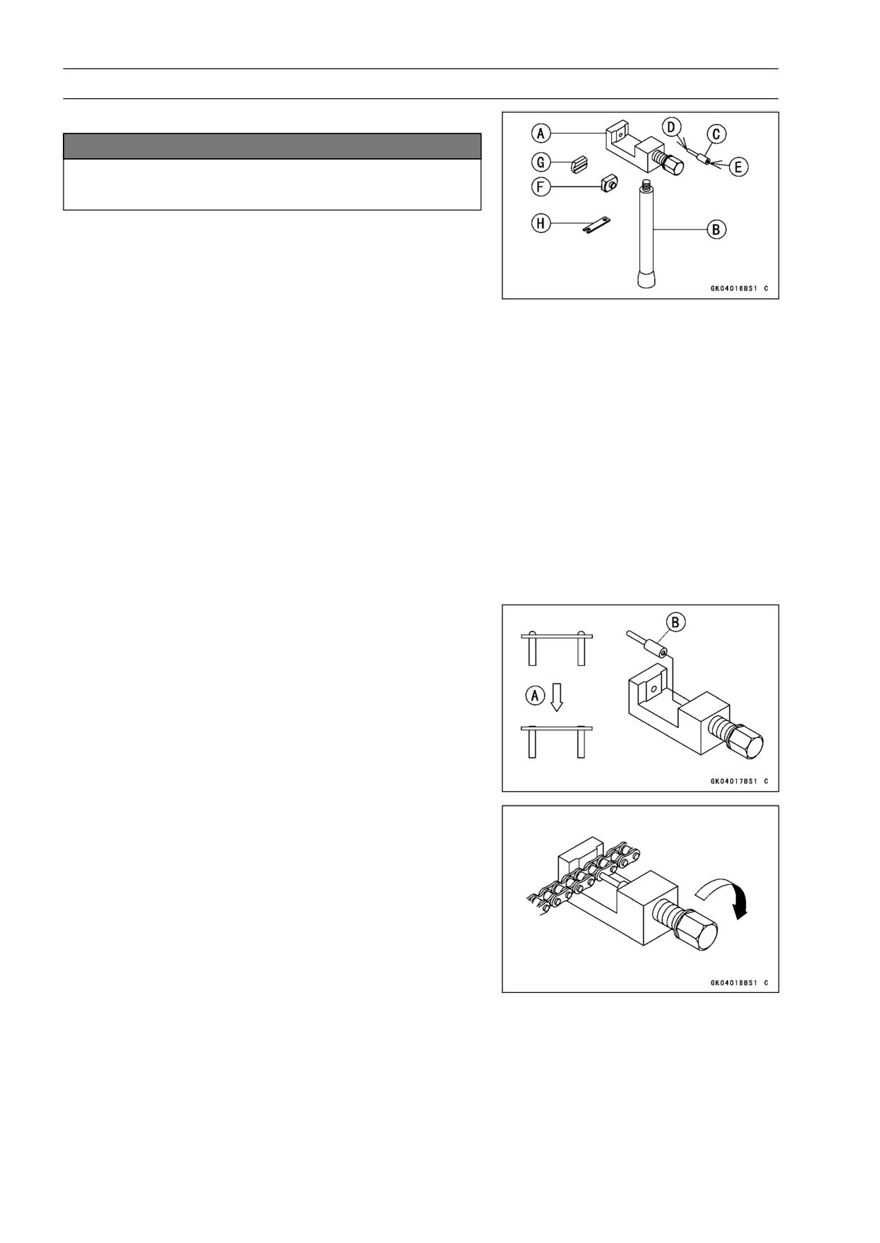
Body [A]
Handlebar [B]
Cutting and Riveting Pin [C]
For Cutting [D]
For Riveting [E]
Plate Holder (A) [F]
Plate Holder (B) [G]
Gauge [H]
• Remove:
Chain Cover (see Drive Chain Removal)
Engine Sprocket Cover (see Engine Sprocket Removal)
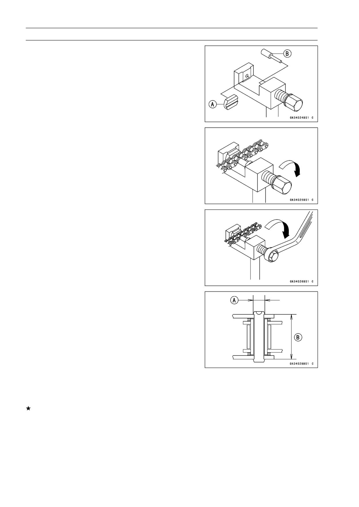
• Grind [A] the pin head to make it flat.
• Set the cutting and rivetting pin [B] as shown.
• Screw the pin holder until it touches the link pin.
• Be sure that the cutting pin hits center of the link pin.
FINAL DRIVE 11-9
Drive Chain
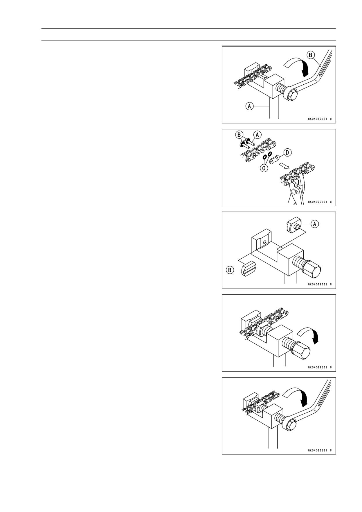
• Screw the handlebar [A] into the body.
• Turn the pin holder with the wrench [B] clockwise to ex-
tract the link pin.
• Replace the link pin, link plate and grease seals.
• Apply grease to the link pins [A] and grease the seals [B]
[C].
• Engage the drive chain on the engine and rear sprockets.
• Insert the link pins in the drive chain ends.
• Install the grease seals [C].
• Install the link plate [D] so that the mark faces out.
• Push the link plate by hand or plier to fix it.
• Be sure to set the grease seals correctly.
• Set the plate holder (A) [A] and plate holder (B) [B] on the
body.
• Fit the plate holder (A) to the link plate.
• Turn the pin holder by hand until the plate holder (B)
touches the other link plate.
• Turn the pin holder by a wrench clockwise until two pins
of link come into groove of the plate holder (A).
• Take off the plate holder.
11-10 FINAL DRIVE
Drive Chain
• Set the plate holder (B) [A] and the cutting and rivetting
pin [B] as shown.
• Turn the pin holder until the rivetting pin touches the link
pin.
• Turn the wrench clockwise until the tip of rivetting pin con-
tact with the link pin.
• Rivet it.
• Repeat the same procedure for the other link pin.
• After staking, check the staked area of the link pin for
cracks.
• Measure the outside diameter [A] of the link pin and link
plates width [B].
Link Pin Outside Diameter
Standard:
EX250J8 ∼ JA
5.3 ∼ 5.7 mm (0.21 ∼ 0.22 in.)
EX250JB ∼ JC
5.7 ∼ 6.0 mm (0.23 ∼ 0.24 in.)
Link Plates Outside Width
Standard:
EX250J8 ∼ JA
17.35 ∼ 17.50 mm (0.683 ∼ 0.689 in.)
EX250JB ∼ JC
17.25 ∼ 17.55 mm (0.679 ∼ 0.691 in.)
If the reading exceeds the specified length, cut and rejoin
the chain again.
• Check:
Movement of the Rollers
• Adjust the drive chain slack after installing the chain (see
Drive Chain Slack Inspection in the Periodic Maintenance
chapter).
FINAL DRIVE 11-11
Sprocket, Coupling
Engine Sprocket Removal
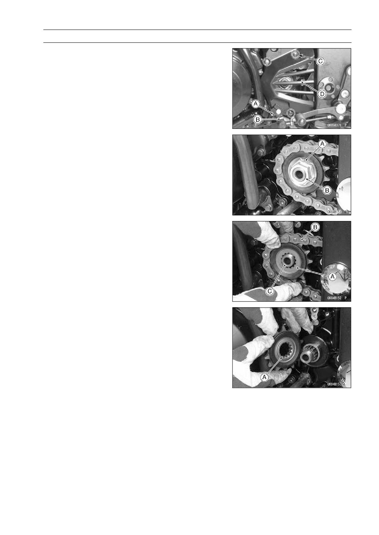
• Remove:
Shift Lever Link Bolt [A]
Shift Shaft [B]
Engine Sprocket Cover Bolts [C]
• Remove the engine sprocket cover [D].
• Flatten out the bended washer [A].
• Remove the engine sprocket nut [B] and washer.
NOTE
○When loosening the engine sprocket nut, hold the rear
brake on.
• Raise the rear wheel off the ground.
• Remove the axle cotter pin, and loosen the rear axle nut.
• Loosen the both chain adjuster locknut to loosen the drive
chain.
• Remove the drive chain from the rear sprocket toward the
right.
• Pull the engine sprocket [A] with drive chain [B] off the
output shaft [C].
• Disengage the drive chain from the engine sprocket.
Engine Sprocket Installation
• Replace the sprocket washer and axle cotter pin.
• Install the engine sprocket onto the shaft the protruding
side [A] of it faces in.
• Apply molybdenum disulfide oil solution to the threads of
the output shaft and the seating surface of the engine
sprocket nut.
• After torquing the engine sprocket nut, bend the one side
of the washer over the nut.
NOTE
○Tighten the nut while applying the rear brake.
Torque - Engine Sprocket Nut: 127 N·m (13 kgf·m, 94 ft·lb)
• Adjust the drive chain slack after installing the sprocket
(see Drive Chain Slack Adjustment in the Periodic Main-
tenance chapter).
• Install the new axle cotter pin, and bend the end of it
surely.
• Install the engine sprocket cover.
• Install the shift lever onto the shift shaft aligning the mark
which is marked before removing.
11-12 FINAL DRIVE
Sprocket, Coupling
Rear Sprocket Removal
• Remove the rear wheel (see Rear Wheel Removal in the
Wheels/Tires chapter).
NOTICE
Do not lay the wheel on the ground with the disc
facing down. This can damage or warp the disc.
Place blocks under the wheel so that the disc does
not touch the ground.
• Pull out the coupling collar from the left, and coupling
sleeve from the right.
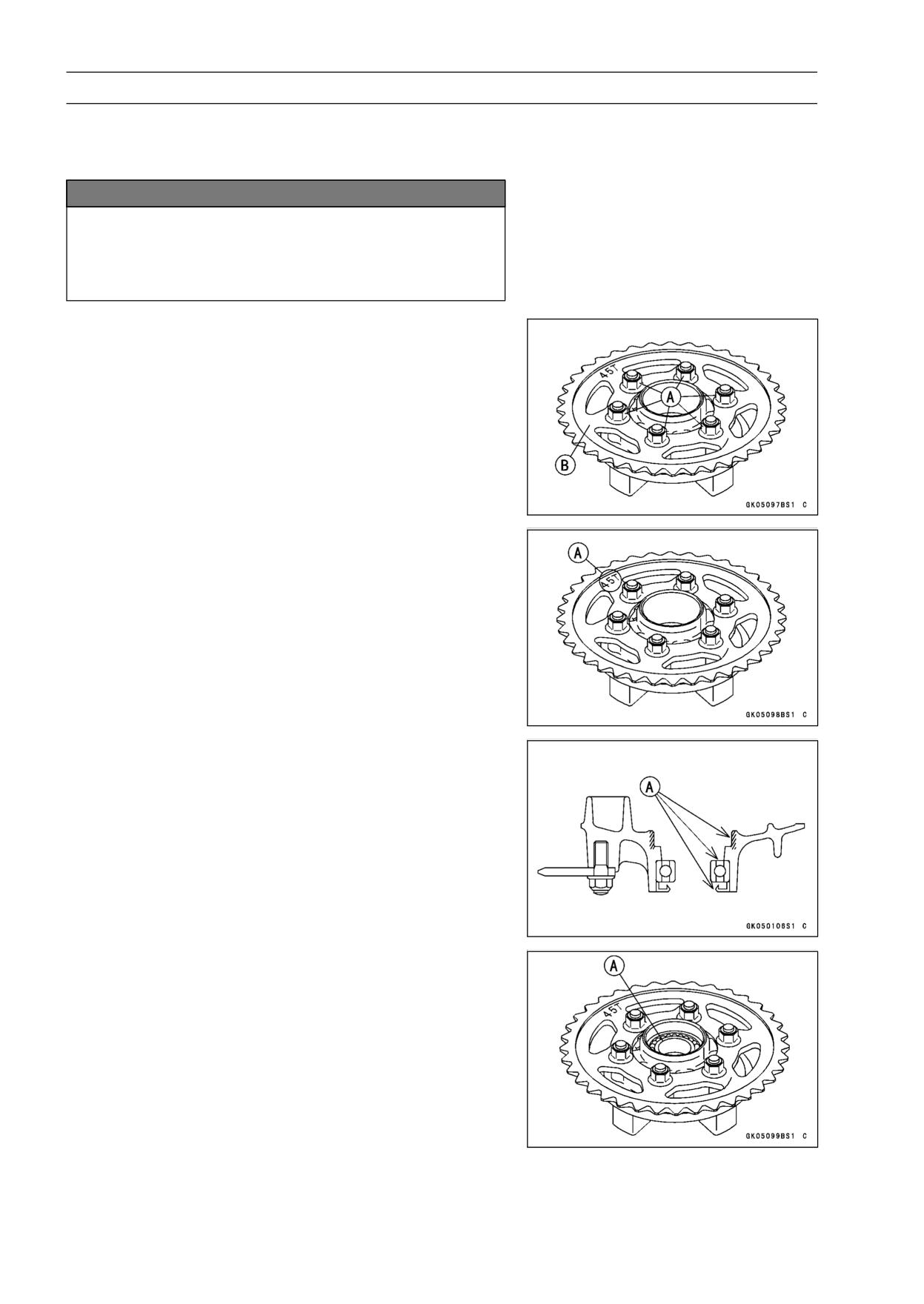
• Remove the rear sprocket nuts [A].
• Remove the rear sprocket [B].
Rear Sprocket Installation
• Install the sprocket with the tooth number marking [A] out-
ward.
• Replace the rear sprocket nuts with the new ones.
• Install the rear sprocket nuts.
Torque - Rear Sprocket Nuts: 59 N·m (6.0 kgf·m, 44 ft·lb)
• Install the rear wheel (see Rear Wheel Installation in the
Wheels/Tires chapter).
Coupling Installation
• Grease the following and install the coupling.
Coupling Grease Seal [A]
Coupling Internal Surface [A]
Ball Bearing [A]
Coupling Bearing Removal
• Remove:
Coupling
Grease Seal
Bearing [A]
FINAL DRIVE 11-13
Sprocket, Coupling
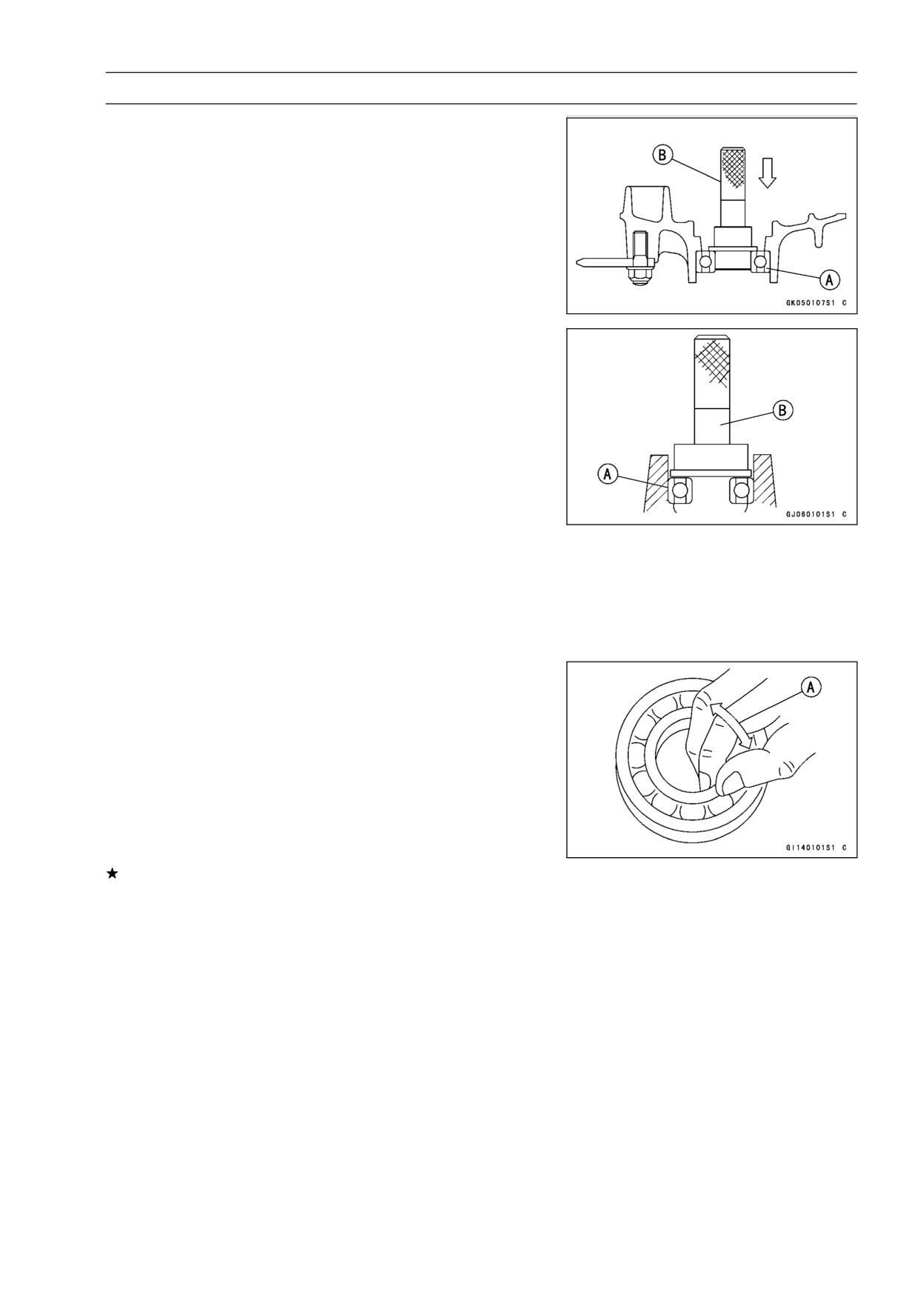
• Remove the bearing [A] by tapping from the wheel side.
Special Tool - Bearing Driver Set: 57001-1129 [B]
Coupling Bearing Installation
• Replace the bearing with a new one.
• Press in the bearing [A] until it is bottomed.
Special Tool - Bearing Driver Set: 57001-1129 [B]
• Pack the bearing with high-temperature grease.
• Replace the grease seal with a new one.
• Press in the grease seal so that the seal surface is flush
with the end of the hole.
○Apply high-temperature grease to the grease seal lips.
Special Tool - Bearing Driver Set: 57001-1129
Coupling Bearing Inspection
Since the coupling bearing is made to extremely close
tolerances, the clearance can not normally be measured.
NOTE
○It is not necessary to remove the coupling bearing for
inspection. If the bearing is removed, it will need to be
replaced with a new one.
• Turn the bearing in the coupling back and forth [A] while
checking for plays, roughness, or binding.
If the bearing play, roughness, or binding is found, replace
the bearing.
Coupling Bearing Lubrication
• Pack the bearing with high-temperature grease. Turn the
bearing around by hand a few times to make sure the
grease is distributed uniformly inside the bearing.
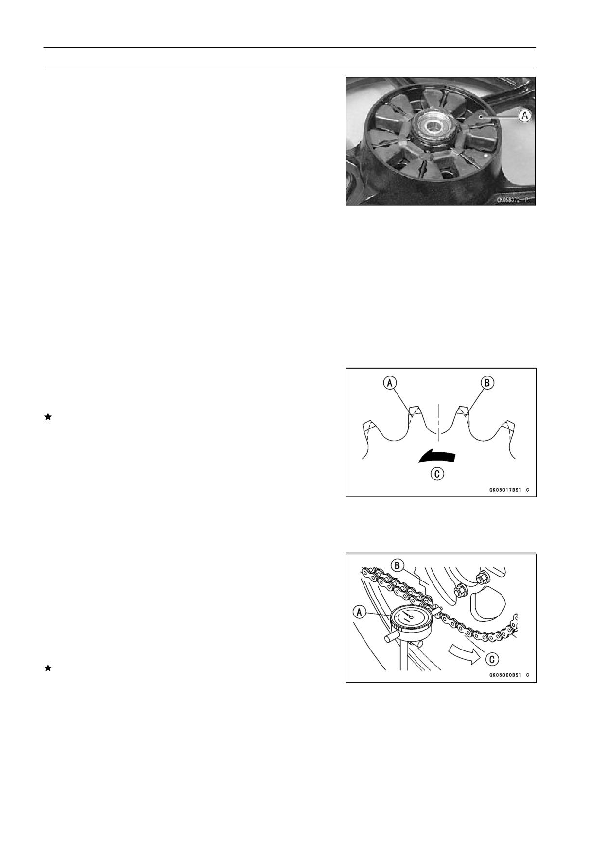
11-14 FINAL DRIVE
Sprocket, Coupling
Coupling Damper Inspection
• Remove the rear wheel coupling, and inspect the rubber
dampers [A].
• Replace the damper if it appears damaged or deterio-
rated.
Grease Seal Inspection and Lubrication
If the grease seals are examined without removing the
seals themselves, look for discoloration (indicating the rub-
ber has deteriorated), hardening, damage to the internal
ribbing, or other damage. If the seal or internal ribbing
has hardened, the clearance between the seal and the axle
sleeve will not be take up, which will allow dirt and moisture
to enter and reach the bearing. If in doubt as to its condition
and whenever the seal is removed for greasing the bearing,
the seal should be replace. The seals are generally dam-
aged upon removal.
Sprocket Wear Inspection
• Visually inspect the engine and rear sprocket teeth for
wear and damage.
If the teeth are worn as illustrated, replace the sprocket,
and inspect the drive chain wear (see Drive Chain Wear
Inspection in the Periodic Maintenance chapter).
[A] Worn Tooth (Engine Sprocket)
[B] Worn Tooth (Rear Sprocket)
[C] Direction of Rotation
NOTE
○If a sprocket requires replacement, the chain is proba-
bly worn also. When replacing a sprocket, inspect the
chain.
Rear Sprocket Warp Inspection
• Raise the rear wheel off the ground with the stand so that
it will turn freely.
• Set a dial gauge [A] against the rear sprocket [B] near the
teeth as shown, and rotate [C] the rear wheel to measure
the sprocket runout (warp). The difference between the
highest and lowest dial gauge readings is the amount of
runout (warp).
If the runout exceeds the service limit, replace the rear
sprocket.
Rear Sprocket Warp
Standard:
TIR 0.4 mm (0.016 in.) or less
Service Limit: TIR 0.5 mm (0.02 in.)
BRAKES 12-1
Brakes
Table of Contents
Exploded View
12-2
Specifications
12-6
Special Tool
12-7
Brake Lever, Brake Pedal
12-8
Brake Pedal Position Inspection
12-8
Brake Pedal Position Adjustment
12-8
Calipers
12-9
Front Caliper Removal
12-9
Rear Caliper Removal
12-9
Caliper Installation
12-9
Caliper Disassembly
12-10
Caliper Assembly
12-10
Caliper Fluid Seal Damage
12-10
Rear Caliper Dust Boot and Friction Boot Damage
12-11
Caliper Piston and Cylinder Damage Inspection
12-11
Caliper Holder Shaft Wear
12-11
Brake Pads
12-12
Brake Pad Removal
12-12
Brake Pad Installation
12-12
Brake Pad Wear Inspection
12-12
Master Cylinder
12-13
Front Master Cylinder Removal
12-13
Front Master Cylinder Installation
12-13
Rear Master Cylinder Removal
12-14
12
Rear Master Cylinder Installation
12-14
Rear Brake Reservoir Removal
12-15
Rear Brake Reservoir Installation
12-15
Front Master Cylinder Disassembly
12-15
Rear Master Cylinder Disassembly
12-15
Master Cylinder Assembly
12-16
Master Cylinder Inspection
12-16
Brake Disc
12-17
Brake Disc Removal
12-17
Brake Disc Installation
12-17
Brake Disc Wear Inspection
12-17
Brake Disc Warp Inspection
12-17
Brake Fluid
12-18
Brake Fluid Level Inspection
12-18
Brake Fluid Change
12-18
Brake Line Bleeding
12-18
Brake Hose
12-21
Brake Hose Removal/Installation
12-21
Brake Hose Inspection
12-21
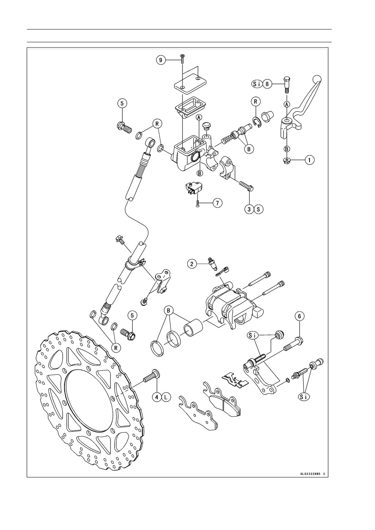
12-2 BRAKES
Exploded View
BRAKES 12-3
Exploded View
Torque
No.
Fastener
Remarks
N·m
kgf·m
ft·lb
1
Brake Lever Pivot Bolt Locknut
5.9
0.6
52 in·lb
2
Bleed Valve
5.5
0.55
49 in·lb
3
Front Master Cylinder Clamp Bolts
8.8
0.9
78 in·lb
S
4
Brake Disc Mounting Bolts
27
2.8
20
L
5
Brake Hose Banjo Bolts
25
2.5
18
6
Front Caliper Mounting Bolts
25
2.5
18
7
Front Brake Light Switch Screw
1.0
0.1
9 in·lb
8
Brake Lever Pivot Bolt
1.0
0.1
9 in·lb
9
Front Reservoir Cap Screws
1.5
0.15
13 in·lb
B: Apply brake fluid.
L: Apply a non-permanent locking agent.
R: Replacement parts
S: Follow the specific tightening sequence.
Si: Apply silicone grease.
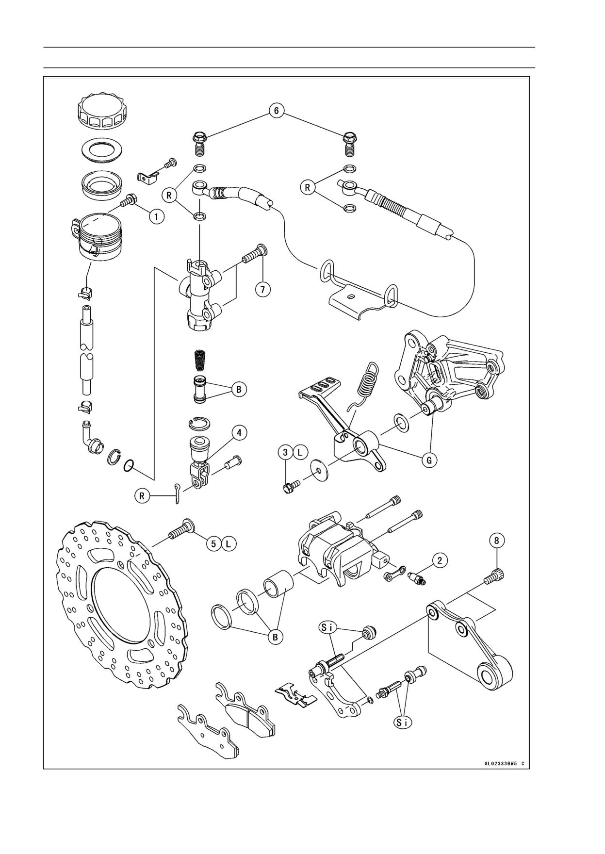
12-4 BRAKES
Exploded View
BRAKES 12-5
Exploded View
Torque
No.
Fastener
Remarks
N·m
kgf·m
ft·lb
1
Reservoir Mounting Bolt
6.9
0.7
61 in·lb
2
Bleed Valve
5.5
0.55
49 in·lb
3
Brake Pedal Pivot Bolt
8.8
0.9
78 in·lb
L
4
Push Rod Locknut
18
1.8
13
5
Brake Disc Mounting Bolts
27
2.8
20
L
6
Brake Hose Banjo Bolts
25
2.5
18
7
Rear Master Cylinder Mounting Bolts
25
2.5
18
8
Rear Caliper Mounting Bolts
25
2.5
18
B: Apply brake fluid.
G: Apply grease.
L: Apply a non-permanent locking agent.
R: Replacement parts
Si: Apply silicone grease.
12-6 BRAKES
Specifications
Item
Standard
Service Limit
Brake Pedal
Pedal Free Play
Non-adjustable
- - -
Pedal Position
About 40 mm (1.6 in.) below footpeg top
- - -
Brake Discs
Thickness:
Front
4.3 ∼ 4.7 mm (0.17 ∼ 0.19 in.)
4.0 mm (0.16 in.)
Rear
4.8 ∼ 5.2 mm (0.19 ∼ 0.20 in.)
4.5 mm (0.18 in.)
Runout
TIR 0.15 mm (0.006 in.) or less
TIR 0.3 mm (0.01 in.)
BRAKES 12-7
Special Tool
Inside Circlip Pliers:
57001-143
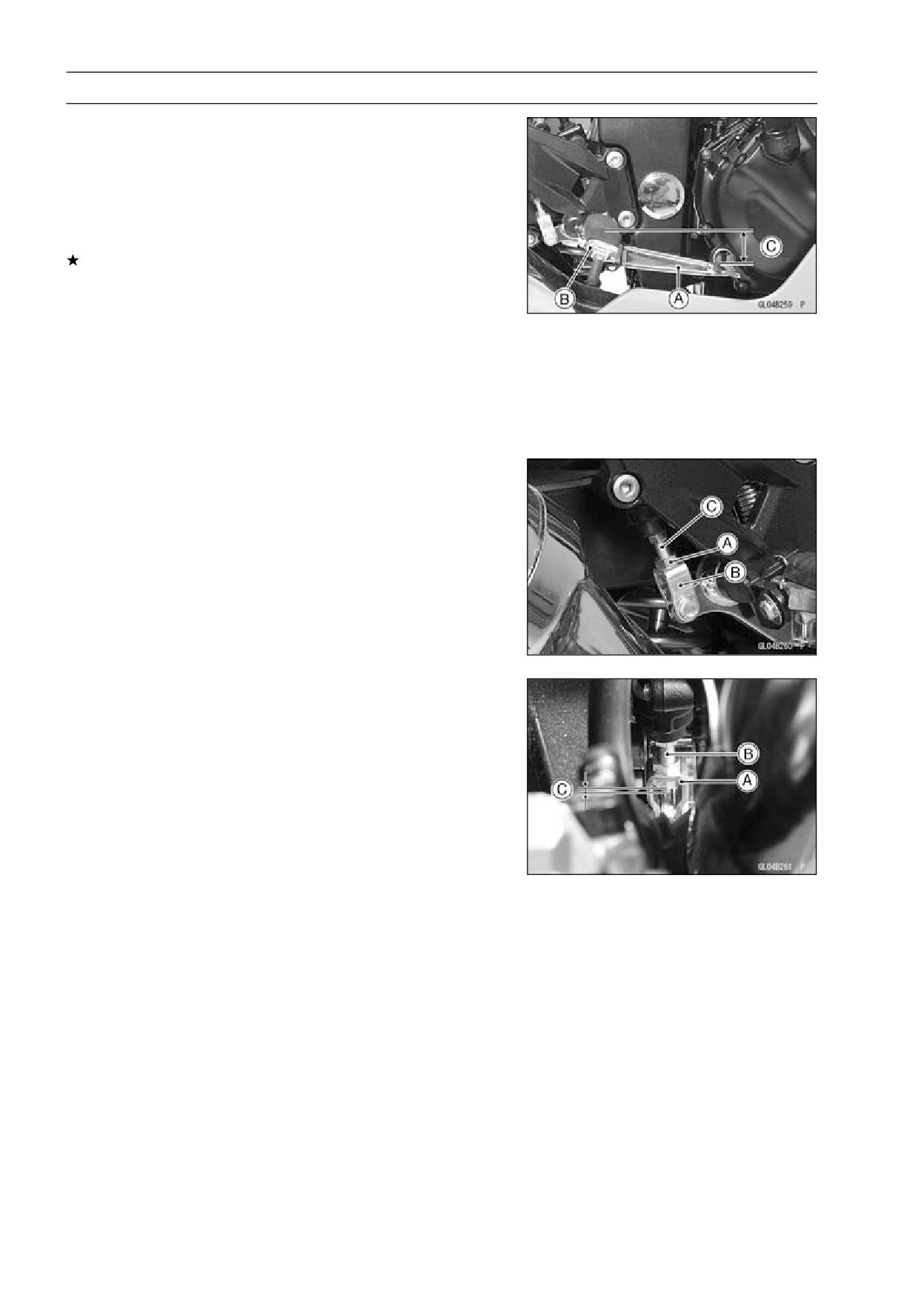
12-8 BRAKES
Brake Lever, Brake Pedal
Brake Pedal Position Inspection
• Check that the brake pedal [A] is in the correct position.
[B] Footpeg
Pedal Position
Standard: About 40 mm (1.6 in.) [C] below top of
footpeg
If it is incorrect, adjust the brake pedal position.
Brake Pedal Position Adjustment
NOTE
○Usually it is not necessary to adjust the pedal position,
but always adjust it when push rod locknut has been
loosened.
• Loosen the locknut [A] and up or down the clevis [B] by
turning the adjuster [C] to adjust the brake pedal position.
• Tighten the locknut with specified torque.
Torque - Push Rod Locknut: 18 N·m (1.8 kgf·m, 13 ft·lb)
NOTE
○If the pedal position cannot be adjusted by turning the
clevis [A], the brake pedal may be deformed or incor-
rectly installed.
○If the brake rod [B] protrusion is 3.5 ∼ 5.5 mm (0.14 ∼
0.22 in.) [C] below the nut, the pedal position will be
with in the standard range (about 40 mm (1.6 in.)).
• Check the brake pedal position, and readjust it if neces-
sary.
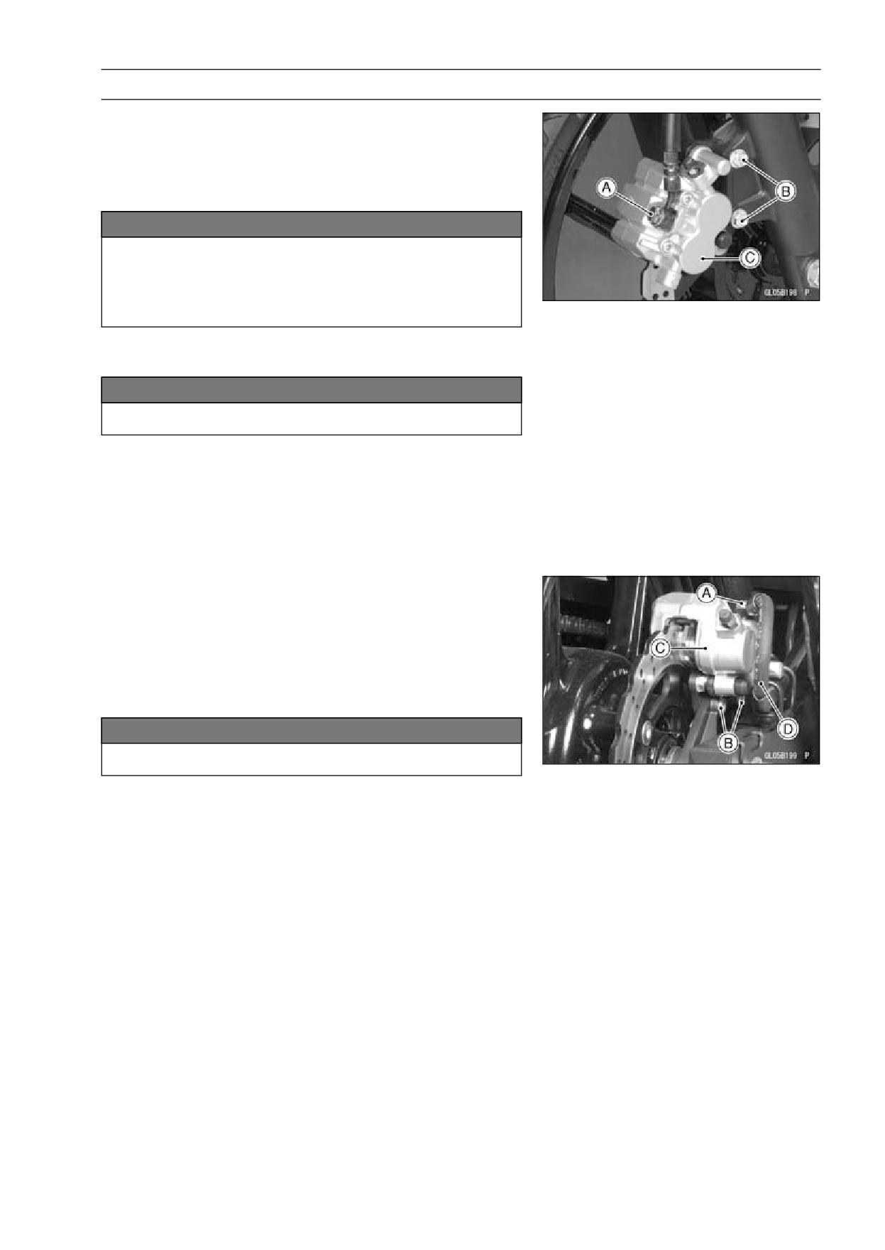
BRAKES 12-9
Calipers
Front Caliper Removal
• Loosen the banjo bolt [A] at the brake hose lower end,
and tighten it loosely.
• Unscrew the caliper mounting bolts [B], and detach the
caliper [C] from the disc.
NOTICE
Do not loosen the caliper assembly bolts. Take out
only the caliper mounting bolts for caliper removal.
Loosening the caliper assembly bolts will cause
brake fluid leakage.
• Unscrew the banjo bolt and remove the brake hose from
the caliper (see Brake Hose Removal/Installation).
NOTICE
Immediately wash away any brake fluid that spills.
NOTE
○If the caliper is to be disassembled after removal and if
compressed air is not available, disassemble the caliper
before the brake hose is removed (see Caliper Rubber
Parts Replacement in the Periodic Maintenance chap-
ter).
Rear Caliper Removal
• Loosen the banjo bolt [A] at the brake hose lower end,
and tighten it loosely.
• Unscrew the caliper mounting bolts [B], and detach the
caliper [C] from the disc.
• Unscrew the banjo bolt and remove the brake hose [D]
from the caliper (see Brake Hose Removal/Installation).
NOTICE
Immediately wash away any brake fluid that spills.
NOTE
○If the caliper is to be disassembled after removal and if
compressed air is not available, disassemble the caliper
before the brake hose is removed (see Caliper Rubber
Parts Replacement in the Periodic Maintenance chap-
ter).
Caliper Installation
• Install the caliper and brake hose lower end.
○Replace the washers on each side of hose fitting with new
ones.
• Tighten:
Torque - Front Caliper Mounting Bolts: 25 N·m (2.5 kgf·m,
18 ft·lb)
Rear Caliper Mounting Bolts: 25 N·m (2.5 kgf·m,
18 ft·lb)
Brake Hose Banjo Bolts: 25 N·m (2.5 kgf·m, 18
ft·lb)
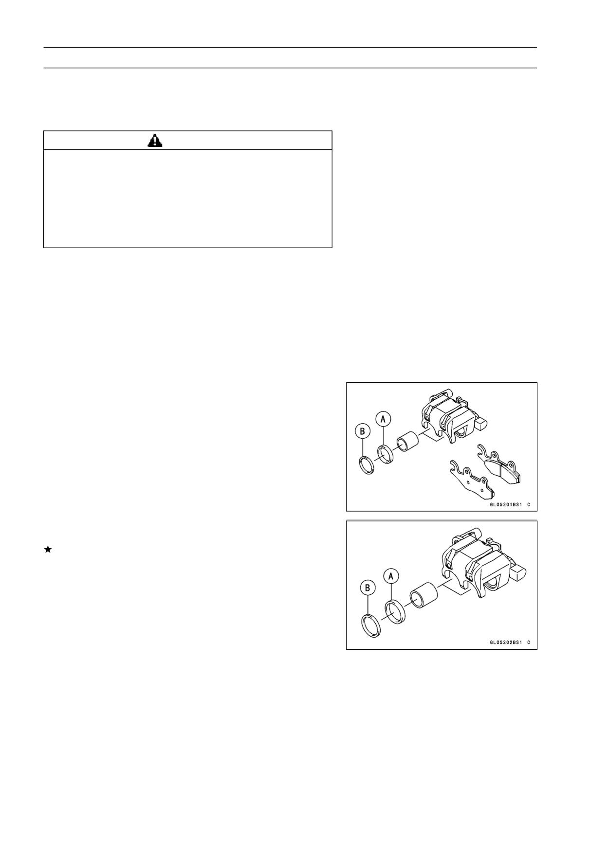
12-10 BRAKES
Calipers
• Check the fluid level in the brake reservoirs.
• Bleed the brake line (see Brake Line Bleeding).
• Check the brake for good braking power, no brake drag,
and no fluid leakage.
WARNING
After servicing, it takes several applications of the
brake lever or pedal before the brake pads contact
the disc, which could result in increased stopping
distance and cause an accident resulting in injury
or death. Do not attempt to ride the motorcycle until
a firm brake lever or pedal is obtained by pumping
the lever or pedal until the pads are against the disc.
Caliper Disassembly
• Refer to Caliper Rubber Parts Replacement in the Peri-
odic Maintenance chapter (see Caliper Rubber Parts Re-
placement in the Periodic Maintenance chapter).
Caliper Assembly
• Refer to Caliper Rubber Parts Replacement in the Peri-
odic Maintenance chapter (see Caliper Rubber Parts Re-
placement in the Periodic Maintenance chapter).
Caliper Fluid Seal Damage
The fluid seal (piston seal) [A] is placed around the pis-
ton to maintain clearance between the pad and the disc. If
the seal is in a poor condition, it could lead the pad to wear
excessively or the brake to drag, which may cause the tem-
perature of the discs or the brake fluid to increase.
• Replace the fluid seal if it exhibits any of the conditions
listed below.
○Brake fluid leakage around the pad.
○Brakes overheat.
○Considerable difference in inner and outer pad wear.
○Seal and piston are stuck together.
If the fluid seal is replaced, replace the dust seal [B] as
well. Also, replace all seals every other time the pads are
changed.
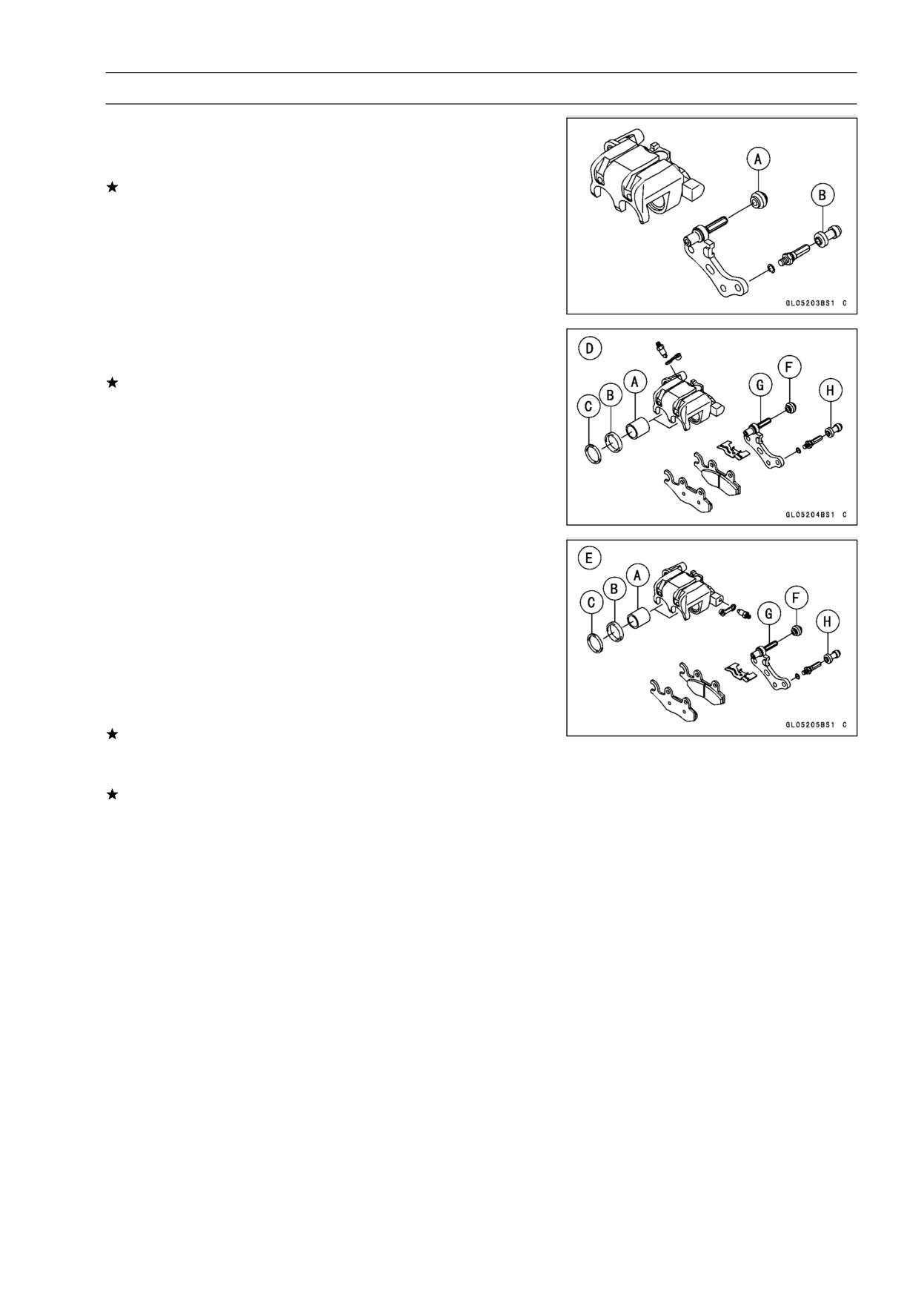
BRAKES 12-11
Calipers
Rear Caliper Dust Boot and Friction Boot Damage
• Check that the dust boot [A] and friction boot [B] are not
cracked, worn, swollen, or otherwise damaged.
If they show any damage, replace it.
Caliper Piston and Cylinder Damage Inspection
• Visually inspect the piston [A] and cylinder surfaces.
Replace the caliper if the cylinder and piston are badly
scores or rusty.
Fluid Seal [B]
Dust Seal [C]
Front Caliper [D]
Rear Caliper [E]
Dust Boot [F]
Caliper Holder Shaft Wear
The caliper body must slide smoothly on the caliper holder
shafts [G]. If the body does not slide smoothly, one pad
will wear more than the other, pad wear will increase, and
constant drag on the disc will raise brake and brake fluid
temperature.
• Check to see that the caliper holder shafts are not badly
worn or stepped, and that the rubber boots [H] are not
damaged.
If the rubber boot is damaged, replace the rubber boot. To
replace the rubber boot, remove the pads and the caliper
bracket.
If the caliper holder shaft is damage, replace the caliper
bracket.
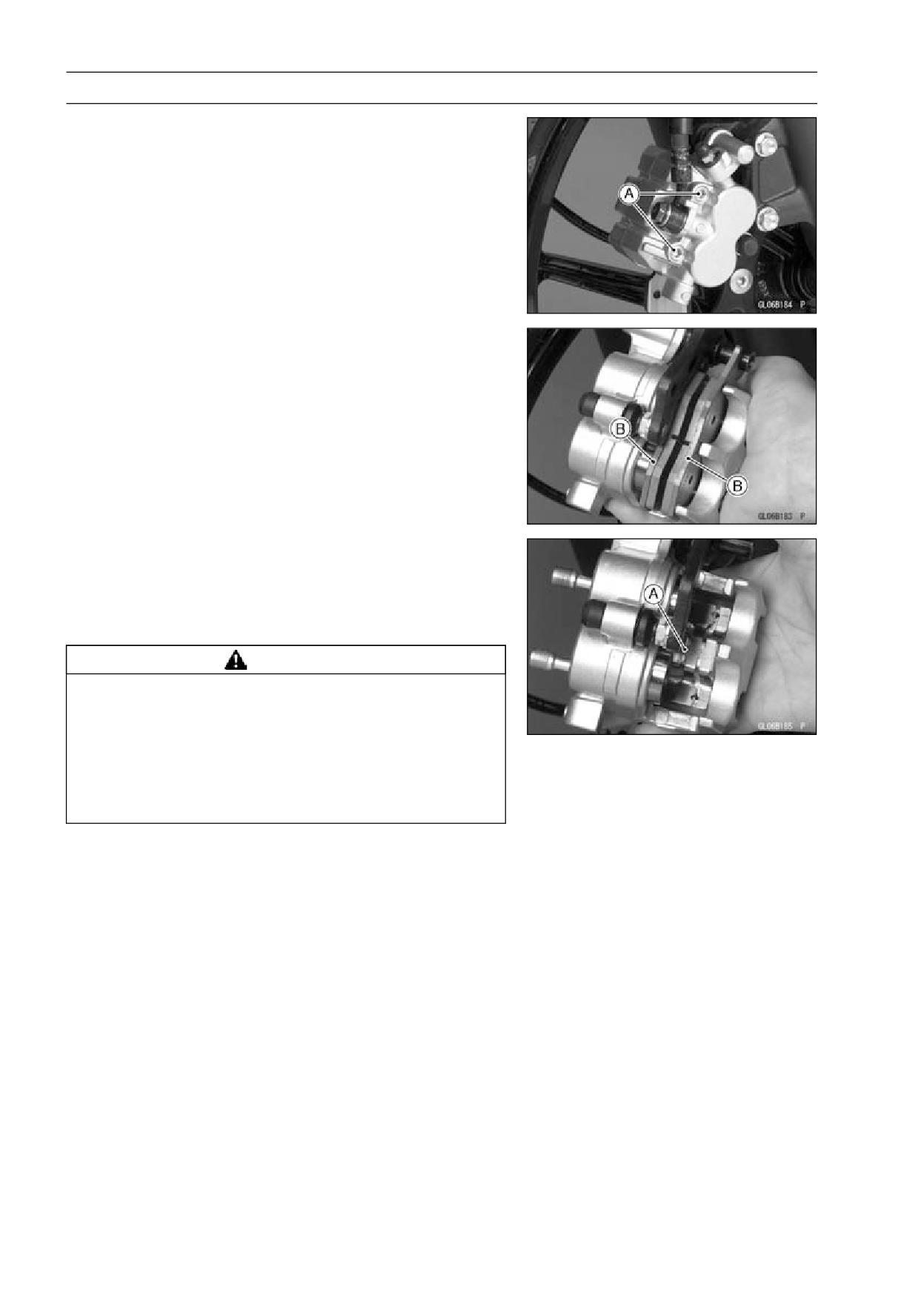
12-12 BRAKES
Brake Pads
Brake Pad Removal
○The procedure to remove the front brake pad is as follows.
Removing the rear brake pad is the same as for the front
brake pad.
• Loosen the holder shaft [A].
• Remove the caliper (see Front/Rear Caliper Removal).
• Draw out the holder shaft.
• Remove the pads [B].
Brake Pad Installation
• Push the caliper pistons by hand as far as they will go.
• Install the pad on the piston side first, then install the other
pad.
• Install the anti-rattle spring [A] in its correct position.
WARNING
After servicing, it takes several applications of the
brake lever or pedal before the brake pads contact
the disc, which could result in increased stopping
distance and cause an accident resulting in injury
or death. Do not attempt to ride the motorcycle until
a firm brake lever or pedal is obtained by pumping
the lever or pedal until the pads are against the disc.
Brake Pad Wear Inspection
• Refer to Brake Pad Wear Inspection in the Periodic Main-
tenance chapter (see Brake Pad Wear Inspection in the
Periodic Maintenance chapter).
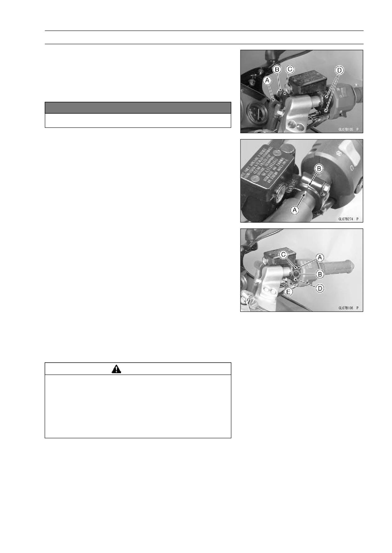
BRAKES 12-13
Master Cylinder
Front Master Cylinder Removal
• Slide the dust cover [A], and remove the banjo bolt [B] to
disconnect the upper brake hose from the master cylinder
[C]. There are flat washers on each side of the hose fitting.
• Remove the front master cylinder clamp bolts [D], and
take off the master cylinder.
NOTICE
Immediately wash away any brake fluid that spills.
Front Master Cylinder Installation
• Install the front master cylinder so that the punch mark [A]
of the handlebar is aligned with the mating surface [B] of
the master cylinder clamp to level the reservoir.
• Install the master cylinder clamp [A] pointing with the ar-
row mark [B] upward.
• Tighten the upper clamp bolt [C] first, and then the lower
clamp bolt [D] with a specified torque. There will be a gap
[E] at the lower part of the clamp after tightening.
• Tighten the banjo bolt with a specified torque after in-
stalling a new flat washer on each side of the brake hose
fitting.
Torque - Front Master Cylinder Clamp Bolts: 8.8 N·m (0.9
kgf·m, 78 in·lb)
Brake Hose Banjo Bolts: 25 N·m (2.5 kgf·m, 18
ft·lb)
• Bleed the brake line (see Brakes Line Bleeding).
• Check the brake for good braking power, no brake drag
and no brake fluid leakage.
WARNING
After servicing, it takes several applications of the
brake lever before the brake pads contact the disc,
which could result in increased stopping distance
and cause an accident resulting in injury or death.
Do not attempt to ride the motorcycle until a firm
brake lever is obtained by pumping the lever until
the pads are against the disc.
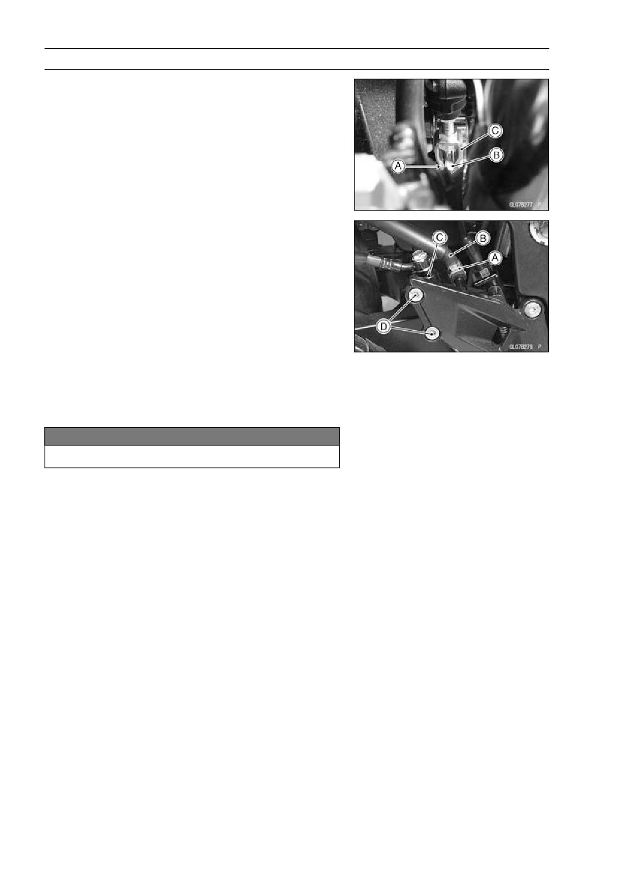
12-14 BRAKES
Master Cylinder
Rear Master Cylinder Removal
• Remove the cotter pin [A] and then pull the joint pin [B]
out of the push rod clevis [C] and brake pedal.
NOTE
○Pull off the joint pin while pressing down the brake
pedal.
• Slide the brake hose clamp [A] out of place (see Brake
Hose and Pipe Replacement in the Periodic Maintenance
chapter).
• Disconnect the brake hoses [B] from the brake hose con-
nector of the master cylinder [C], and temporarily secure
the end of the brake hose so some high place to keep fluid
loss to a minimum and immediately wipe up any brake
fluid that spills.
• Remove the master cylinder mounting bolts [D] and take
the master cylinder off the footpeg bracket.
• Remove the banjo bolt [E] to disconnect the brake hose
from the master cylinder and temporarily secure the end
of the brake hose to some high place to keep fluid loss to
a minimum. There are flat washers on each side of the
hose fitting.
NOTICE
Immediately wash away any brake fluid that spills.
Rear Master Cylinder Installation
• Tighten the banjo bolt with a specified torque after in-
stalling a new flat washer on each side of the brake hose
fitting. Be sure that the metal pipe is properly fitted into
the U-shaped notch in the master cylinder.
Torque - Brake Hose Banjo Bolts: 25 N·m (2.5 kgf·m, 18
ft·lb)
• Tighten the rear master cylinder mounting bolts with a
specified torque.
Torque - Rear Master Cylinder Mounting Bolts: 25 N·m (2.5
kgf·m, 18 ft·lb)
• Connect the brake hose to the master cylinder and re-
place the brake hose clamp in place.
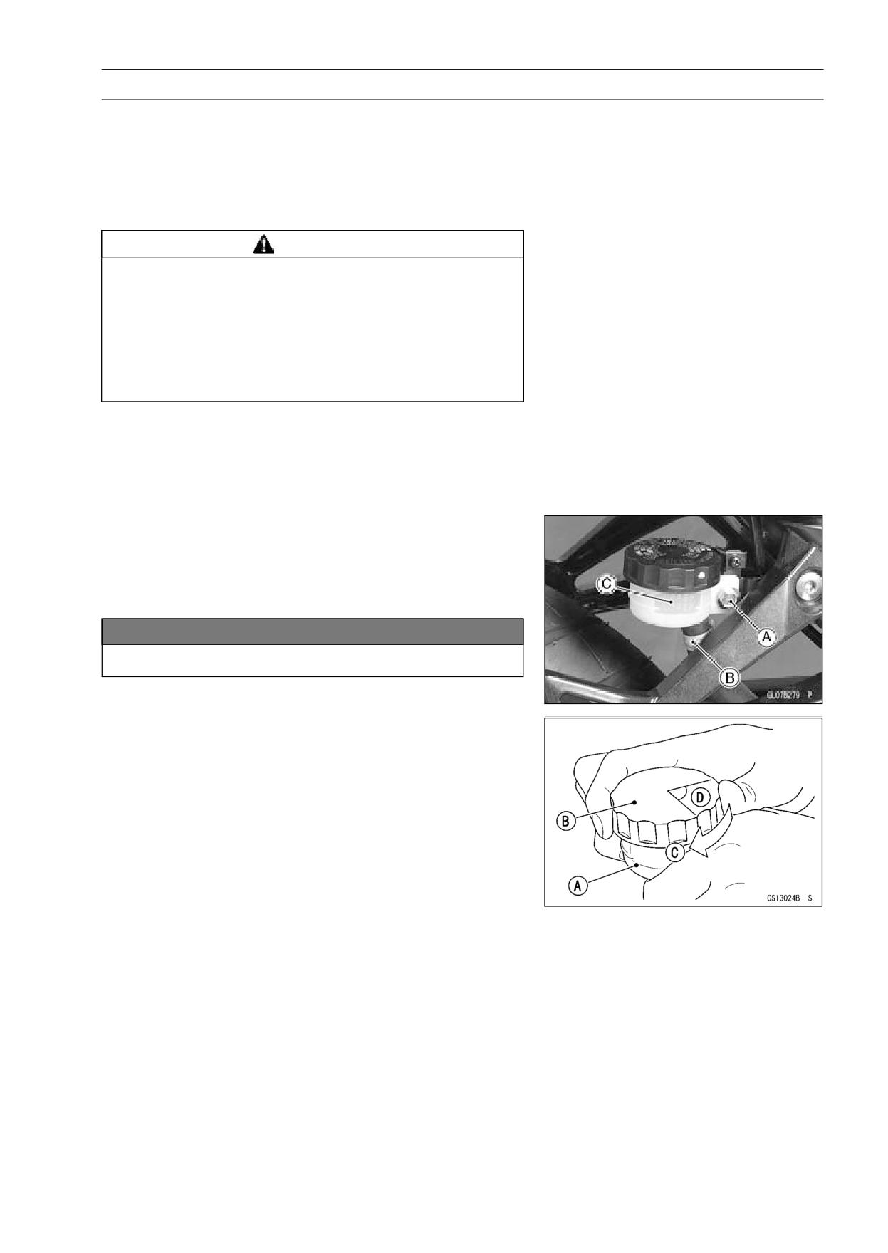
BRAKES 12-15
Master Cylinder
• Connect the push rod clevis to the brake pedal with the
joint pin.
• Install the cotter pin and bend the end of it securely.
• Bleed the brake line (see Brake Line Bleeding).
• Check the brake for good braking power, no brake drag
and no brake fluid leakage.
WARNING
After servicing, it takes several applications of the
brake pedal before the brake pads contact the disc,
which could result in increased stopping distance
and cause an accident resulting in injury or death.
Do not attempt to ride the motorcycle until a firm
brake pedal is obtained by pumping the pedal until
the pads are against the disc.
• Check the brake pedal position (see Brake Pedal Position
Inspection).
• Check the rear brake light switch (see Rear Brake Light
Switch Operation Inspection in the Periodic Maintenance
chapter).
Rear Brake Reservoir Removal
• Remove:
Reservoir mounting Bolt [A]
Brake Hose Clamp (Slide) [B]
Reservoir [C]
NOTICE
Immediately wash away any brake fluid that spills.
Rear Brake Reservoir Installation
• Install the clamp for the brake hose end.
• Fill the reservoir with fresh brake fluid and bleed the brake
line (see Brake Line Bleeding).
• Follow the procedure below to install the rear brake fluid
reservoir cap correctly.
○First, tighten the rear brake fluid reservoir cap [B] clock-
wise [C] by hand until the resistance is felt fully; then,
tighten the cap an additional 1/6 turn [D] while holding the
brake fluid reservoir [A] body.
Front Master Cylinder Disassembly
• Refer to Master Cylinder Rubber Parts Replacement in
the Periodic Maintenance chapter (see Master Cylinder
Rubber Parts Replacement in the Periodic Maintenance
chapter).
Rear Master Cylinder Disassembly
• Refer to Master Cylinder Rubber Parts Replacement in
the Periodic Maintenance chapter (see Master Cylinder
Rubber Parts Replacement in the Periodic Maintenance
chapter).
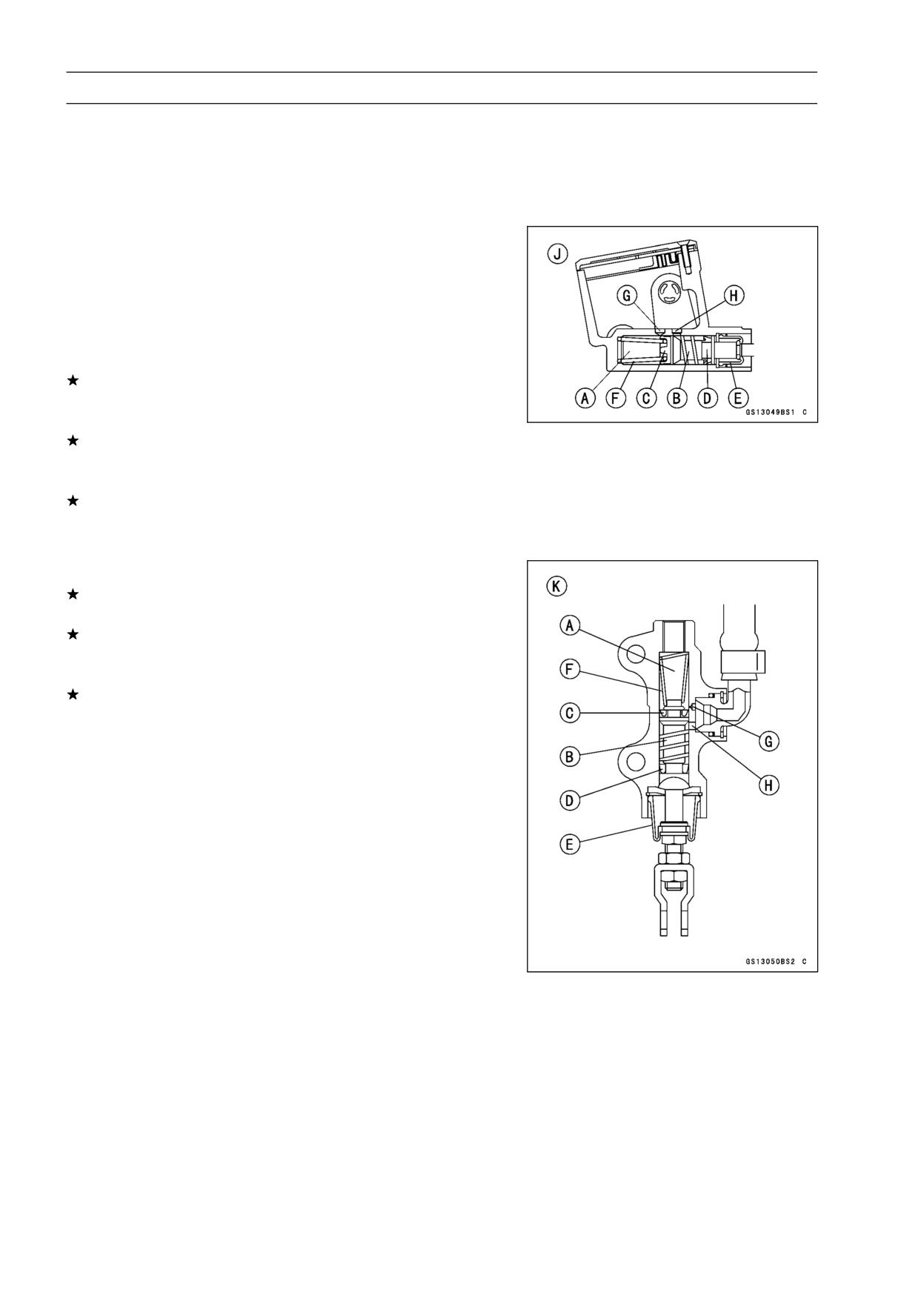
12-16 BRAKES
Master Cylinder
Master Cylinder Assembly
• Refer to Master Cylinder Rubber Parts Replacement in
the Periodic Maintenance chapter (see Master Cylinder
Rubber Parts Replacement in the Periodic Maintenance
chapter).
Master Cylinder Inspection
• Remove the master cylinders (see Front/Rear Master
Cylinder Removal).
• Disassemble the front and rear master cylinders.
• Check that there are no scratches, rust or pitting on the
inner wall [A] of each master cylinder and on the outside
of each piston [B].
If a master cylinder or piston shows any damage, replace
them.
• Inspect the primary cup [C] and secondary cup [D].
If a cup is worn, damaged softened (rotted), or swollen,
the piston assembly should be replaced to renew the
cups.
If fluid leakage is noted at the brake lever, the piston as-
sembly should be replaced to renew the cups.
Front Master Cylinder [J]
• Check the dust covers [E] for damage.
If they are damaged, replace them.
• Check the piston return springs [F] for any damage.
If the springs are damaged, replace them.
• Check that relief port [G] and supply port [H] are not
plugged.
If the relief port becomes plugged, the brake pads will
drag on the disc. Blow the ports clean with compressed
air.
Rear Master Cylinder [K]
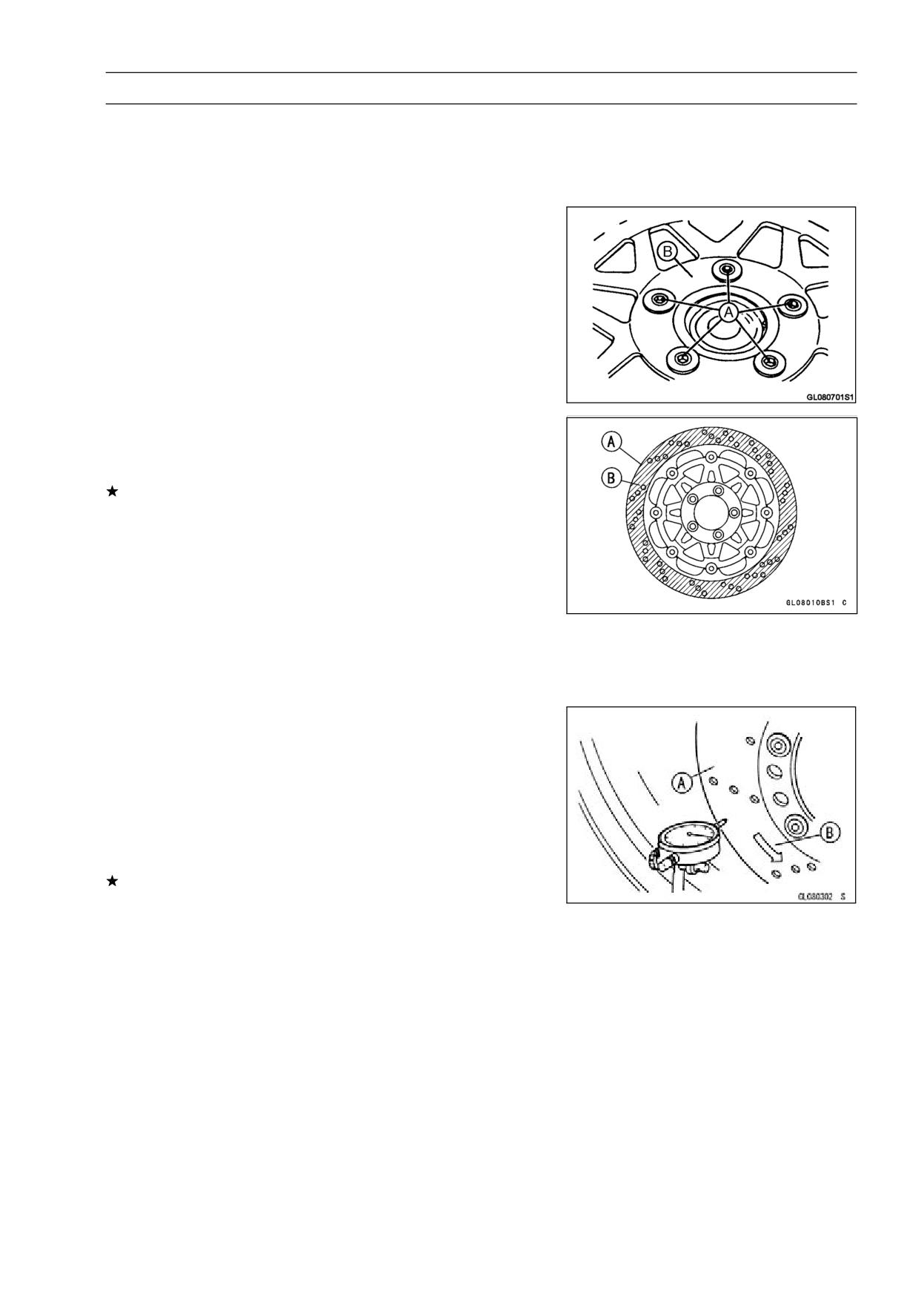
BRAKES 12-17
Brake Disc
Brake Disc Removal
• Remove the wheel (see Front/Rear Wheel Removal in the
Wheels/Tires chapter).
• Unscrew the mounting bolts, and take off the disc.
Brake Disc Installation
• Install the brake disc on the wheel so that the marked side
[B] faces out.
• Apply a non-permanent locking agent to the threads of
the brake disc mounting bolts [A].
• Tighten:
Torque - Brake Disc Mounting Bolts: 27 N·m (2.8 kgf·m, 20
ft·lb)
Brake Disc Wear Inspection
• Measure the thickness of each disc [A] at the point where
it has worn the most.
If the disc has worn past the service limit, replace it.
Measuring Area [B]
Disc Thickness
Standard:
Front
4.3 ∼ 4.7 mm (0.17 ∼ 0.19 in.)
Rear
4.8 ∼ 5.2 mm (0.19 ∼ 0.20 in.)
Service Limit:
Front
4.0 mm (0.16 in.)
Rear
4.5 mm (0.18 in.)
Brake Disc Warp Inspection
• Jack up the motorcycle so that the wheel is off the ground
(see Front/Rear Removal in the Wheels/Tires chapter).
○For front disc inspection, turn the handlebar fully to one
side.
• Set up a dial gauge against the disc [A] as shown and
measure the disc runout, while turning [B] the wheel by
hand.
If the runout exceeds the service limit, replace the disc.
Disc Runout
Service Limit:
0.3 mm (0.01 in.) TIR
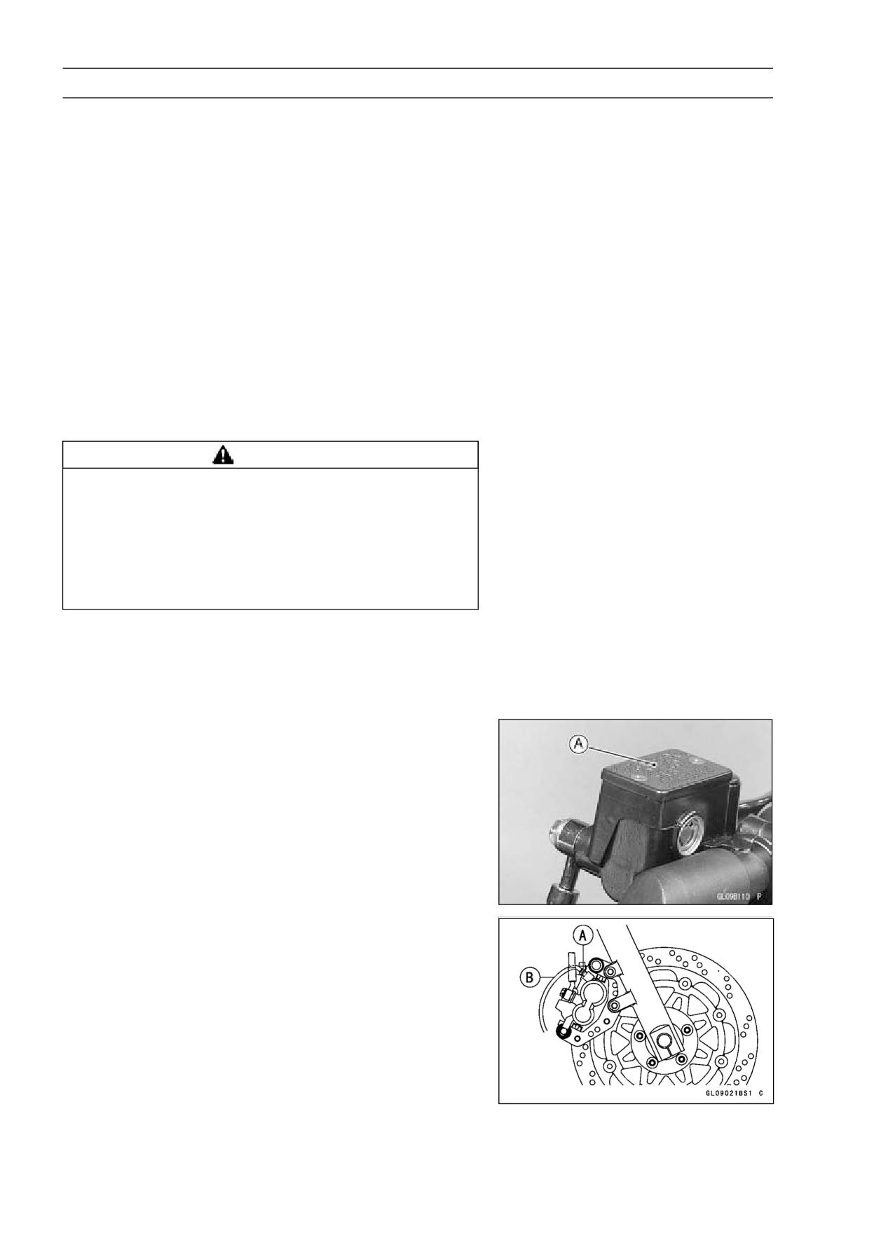
12-18 BRAKES
Brake Fluid
Brake Fluid Level Inspection
• Refer to Brake Fluid Level Inspection in the Periodic Main-
tenance chapter (see Brake Fluid Level Inspection in the
Periodic Maintenance chapter).
Brake Fluid Change
• Refer to Brake Fluid Change in the Periodic Maintenance
chapter (see Brake Fluid Change in the Periodic Mainte-
nance chapter).
Brake Line Bleeding
The brake fluid has a very low compression coefficient so
that almost all the movement of the brake lever or pedal
is transmitted directly to the caliper for braking action. Air,
however, is easily compressed. When air enters the brake
lines, brake lever or pedal movement will be partially used
in compressing the air. This will make the lever or pedal feel
spongy, and there will be a loss in braking power.
WARNING
Air in the brake lines diminish braking performance
and can cause an accident resulting in injury or
death. If the brake lever or pedal has a soft or
"spongy" feeling mushy when it is applied, there
might be air in the brake lines or the brake may be
defective. Do not operate the vehicle and service
the brake system immediately.
NOTE
○The procedure to bleed the front brake line is as follows.
Bleeding the rear brake line is the same as for the front
brake.
• Remove the reservoir cap [A] and diaphragm.
• Fill the reservoir with fresh brake fluid to the upper level
line in the reservoir.
• Slowly pump the brake lever several times until no air
bubbles can be seen rising up through the fluid from the
holes at the bottom of the reservoir.
○Bleed the air completely from the master cylinder by this
operation.
• Remove the rubber cap from the bleed valve [A] on the
caliper.
• Attach a clear plastic hose [B] to the bleed valve, and run
the other end of the hose into a container.
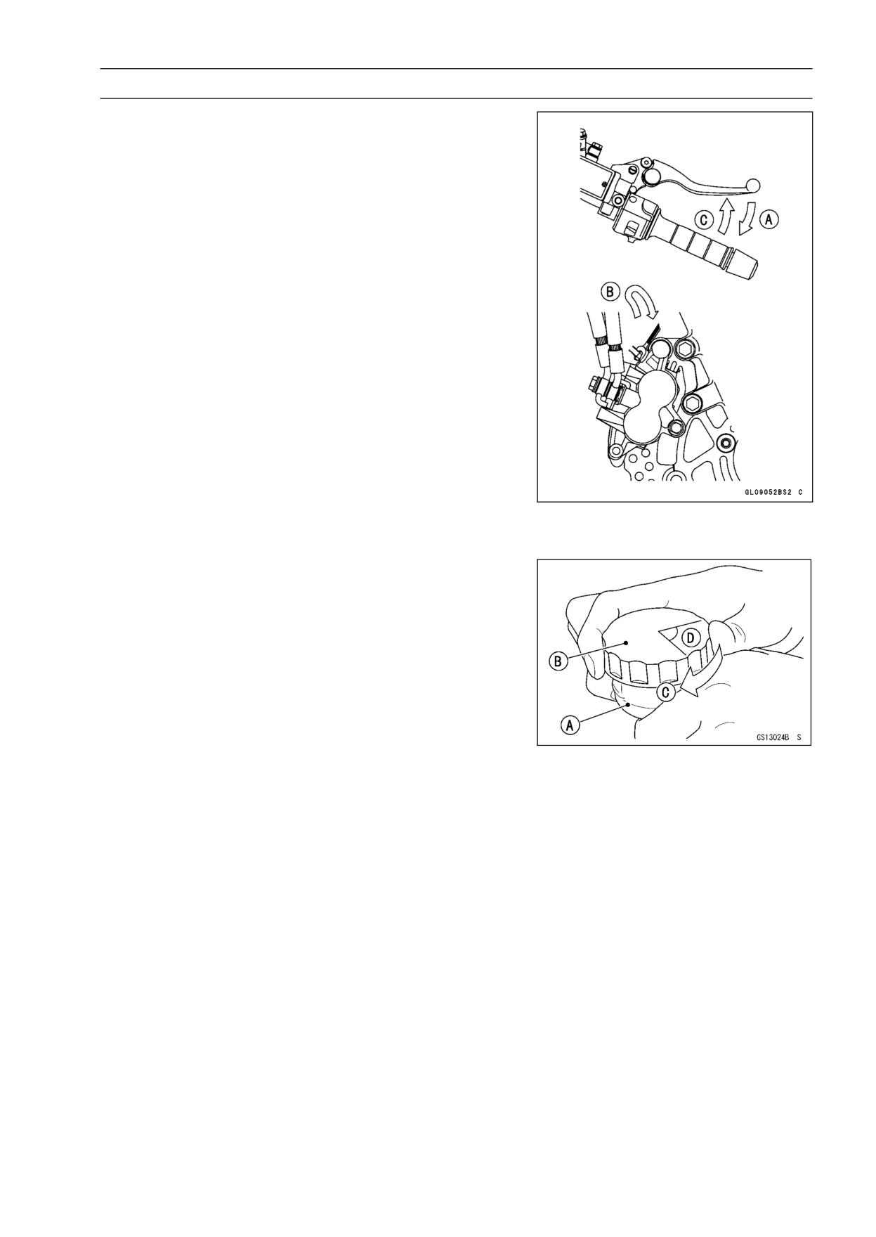
BRAKES 12-19
Brake Fluid
• Bleed the brake line and the caliper.
○Repeat this operation until no more air can be seen com-
ing out into the plastic hose.
1. Pump the brake lever until it becomes hard, and apply
the brake and hold it [A].
2. Quickly open and close [B] the bleed valve while hold-
ing the brake applied.
3. Release the brake [C].
NOTE
○The fluid level must be checked often during the bleed-
ing operation and replenished with fresh brake fluid as
necessary. If the fluid in the reservoir runs completely
out any time during bleeding, the bleeding operation
must be done over again from the beginning since air
will have entered the line.
○Tap the brake hose lightly from the caliper to the reser-
voir for more complete bleeding.
• Remove the clear plastic hose.
• Install the diaphragm and reservoir cap.
• Tighten:
Torque - Front Brake Reservoir Cap Screws: 1.5 N·m (0.15
kgf·m, 13 in·lb)
• Follow the procedure below to install the rear brake fluid
reservoir cap correctly.
○First, tighten the rear brake fluid reservoir cap [B] clock-
wise [C] by hand until slight resistance is felt indicating
that the cap is seated on the reservoir body, then tighten
the cap an additional 1/6 turn [D] while holding the brake
fluid reservoir body [A].
• Tighten the bleed valve, and install the rubber cap.
Torque - Bleed Valve: 5.5 N·m (0.55 kgf·m, 49 in·lb)
• Check the fluid level (see Brake Fluid Level Inspection in
the Periodic Maintenance chapter).
• After bleeding is done, check the brake for good braking
power, no brake drag, and no fluid leakage.
12-20 BRAKES
Brake Fluid
WARNING
When working with the disc brake, observe the pre-
cautions listed below.
1.
Never reuse old brake fluid.
2.
Do not use fluid from a container that has been left
unsealed or that has been open for a long time.
3.
Do not mix two types and brands of fluid for use in
the brake. This lowers the brake fluid boiling point
and could cause the brake to be ineffective. It may
also cause the rubber brake parts to deteriorate.
4.
Don’t leave the reservoir cap off for any length of
time to avoid moisture contamination of the fluid.
5.
Don’t change the fluid in the rain or when a strong
wind is blowing.
6.
Except for the disc pads and disc, use only disc
brake fluid, isopropyl alcohol, or ethyl alcohol for
cleaning of the brake parts. Do not use any other
fluid for cleaning these parts. Gasoline, engine oil,
or any other petroleum distillate will cause deterio-
ration of the rubber parts. Oil spilled on any part will
be difficult to wash off completely and will eventually
deteriorate the rubber used in the disc brake.
7.
When handling the disc pads or disc, be careful that
no disc brake fluid or any oil gets on them. Clean off
any fluid or oil that inadvertently gets on the pads or
disc with a high-flash point solvent. Do not use one
which will leave an oily residue. Replace the pads
with new ones if they cannot be cleaned satisfacto-
rily.
8.
Brake fluid quickly ruins painted surfaces; any
spilled fluid should be completely wiped up imme-
diately.
9.
If any of the brake line fittings or the bleed valve is
opened at any time, the AIR MUST BE BLED FROM
THE BRAKE LINE.
BRAKES 12-21
Brake Hose
Brake Hose Removal/Installation
• Refer to the Brake Hose and Pipe Replacement in the
Periodic Maintenance chapter (see Brake Hose and Pipe
Replacement in the Periodic Maintenance chapter).
Brake Hose Inspection
• Refer to Brake Hose Damage and Installation Condition
Inspection in the Periodic Maintenance chapter (see
Brake Hose Damage and Installation Condition Inspec-
tion in the Periodic Maintenance chapter).
SUSPENSION 13-1
Suspension
Table of Contents
Exploded View
13-2
Specifications
13-4
Special Tools
13-5
Front Fork
13-7
Front Fork Removal
13-7
Front Fork Installation (each fork leg)
13-7
Front Fork Oil Change
13-8
Front Fork Disassembly
13-9
Front Fork Assembly
13-10
Inner Tube/Outer Tube Inspection
13-11
Fork Spring Inspection
13-11
Oil Seal/Dust Seal Inspection
13-11
Rear Shock Absorber
13-12
Spring Preload Adjustment
13-12
Rear Shock Absorber Removal
13-12
Rear Shock Absorber Installation
13-13
Rear Shock Absorber Scrapping
13-13
Swingarm
13-14
Swingarm Removal
13-14
Swingarm Installation
13-14
Swingarm Bearing Removal
13-15
Swingarm Bearing Installation
13-15
Swingarm Bearing, Sleeve Inspection
13-15
Swingarm Lubrication
13-16
Chain Guide Inspection
13-16
13
Tie-Rod, Rocker Arm
13-17
Tie-rods Removal
13-17
Tie-Rod Installation
13-17
Rocker Arm Removal
13-17
Rocker Arm Installation
13-17
Tie-rod, Rocker Arm Bushing Inspection
13-17
Tie-rod, Rocker Arm Sleeve Inspection
13-17
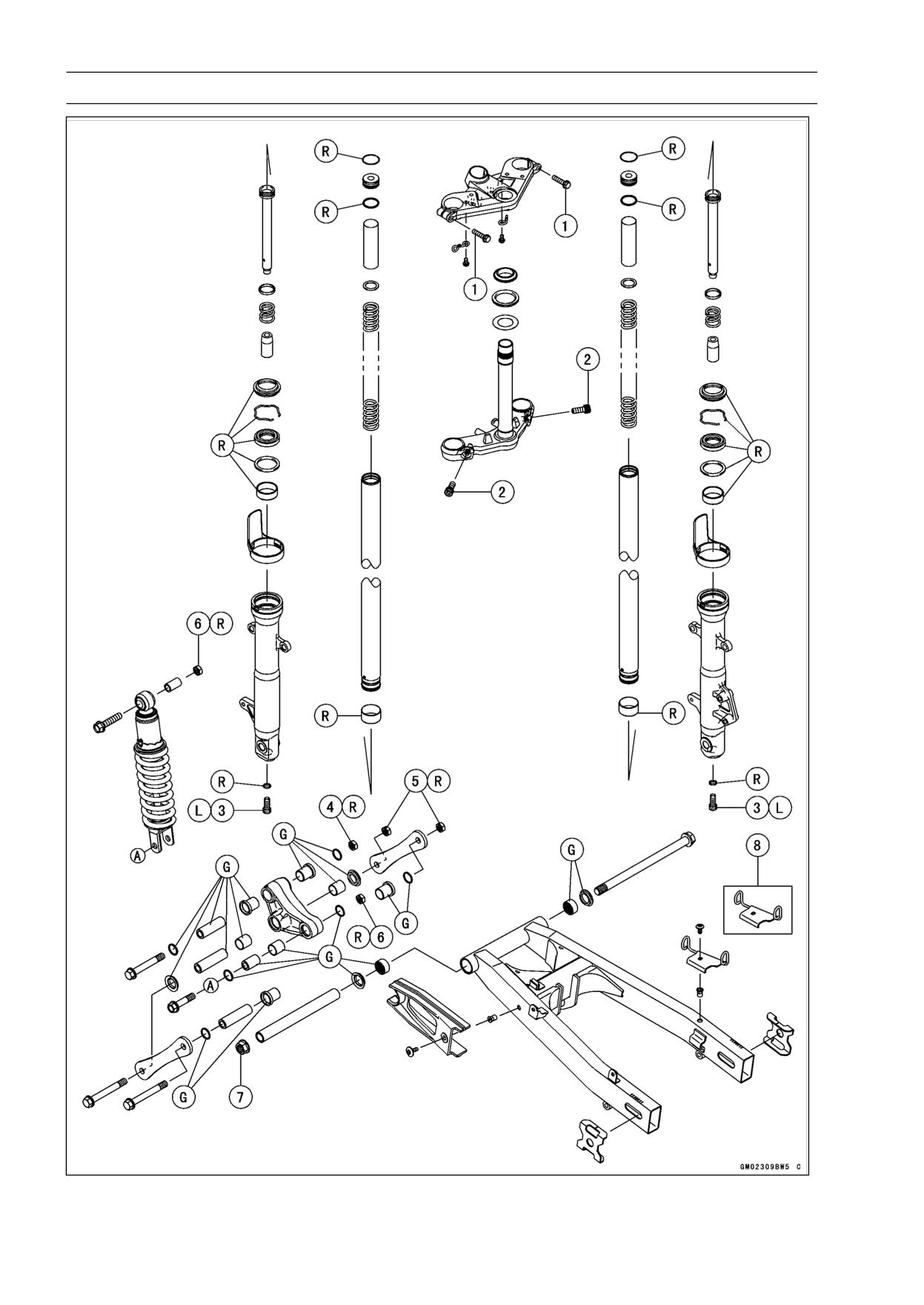
13-2 SUSPENSION
Exploded View
SUSPENSION 13-3
Exploded View
Torque
No.
Fastener
Remarks
N·m
kgf·m
ft·lb
1
Front Fork Clamp Bolts (Upper)
21
2.1
15
2
Front Fork Clamp Bolts (Lower)
30
3.1
22
3
Front Fork Bottom Allen Bolts
20
2.0
15
L
4
Rocker Arm Pivot Nut
59
6.0
44
R
5
Tie-Rod Nuts
59
6.0
44
R
6
Rear Shock Absorber Mounting Nuts
59
6.0
44
R
7
Swingarm Pivot Nut
98
10.0
72
8. EX250J8 Model
L: Apply a non-permanent locking agent.
M: Apply molybdenum disulfide grease.
R: Replacement Parts
13-4 SUSPENSION
Specifications
Item
Standard
Service Limit
Front Fork
Fork Oil:
Viscosity
SHOWA SS08 or equivalent SAE 10W
- - -
Amount (Per Side)
310 mL (10.5 US oz.) (when changing oil)
- - -
360 ±2.5 mL (12.2 ±0.08 US oz.) (after
- - -
disassembly and completely dry)
Fork Oil Level
108 ±2 mm (4.3 ±0.08 in.)
- - -
(Fully compressed, without spring)
Fork Spring Free Length
420.5 mm (16.6 in.)
412 mm (16.2 in.)
Rear Suspension
Rear Shock Absorber Spring
1st position
1 ∼ 5
Preload Adjustment
(Usable range)
Rear Shock Absorber Gas
980 kPa (10 kgf/cm², 142 psi)
- - -
Pressure (non-adjustable)
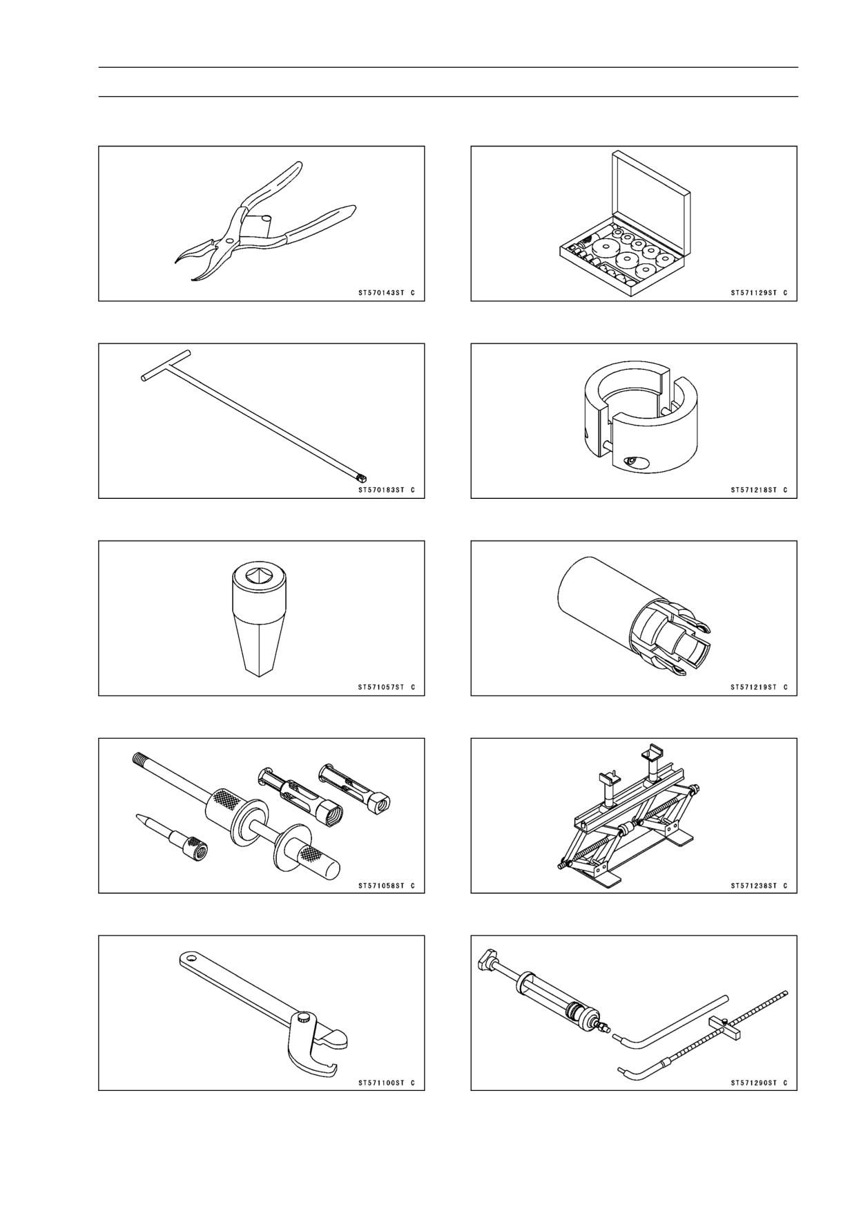
SUSPENSION 13-5
Special Tools
Inside Circlip Pliers:
Bearing Driver Set:
57001-143
57001-1129
Fork Cylinder Holder Handle:
Fork Outer Tube Weight:
57001-183
57001-1218
Fork Cylinder Holder Adapter:
Front Fork Oil Seal Driver:
57001-1057
57001-1219
Oil Seal & Bearing Remover:
Jack:
57001-1058
57001-1238
Steering Stem Nut Wrench:
Fork Oil Level Gauge:
57001-1100
57001-1290
13-6 SUSPENSION
Special Tools
Jack Attachment:
57001-1608
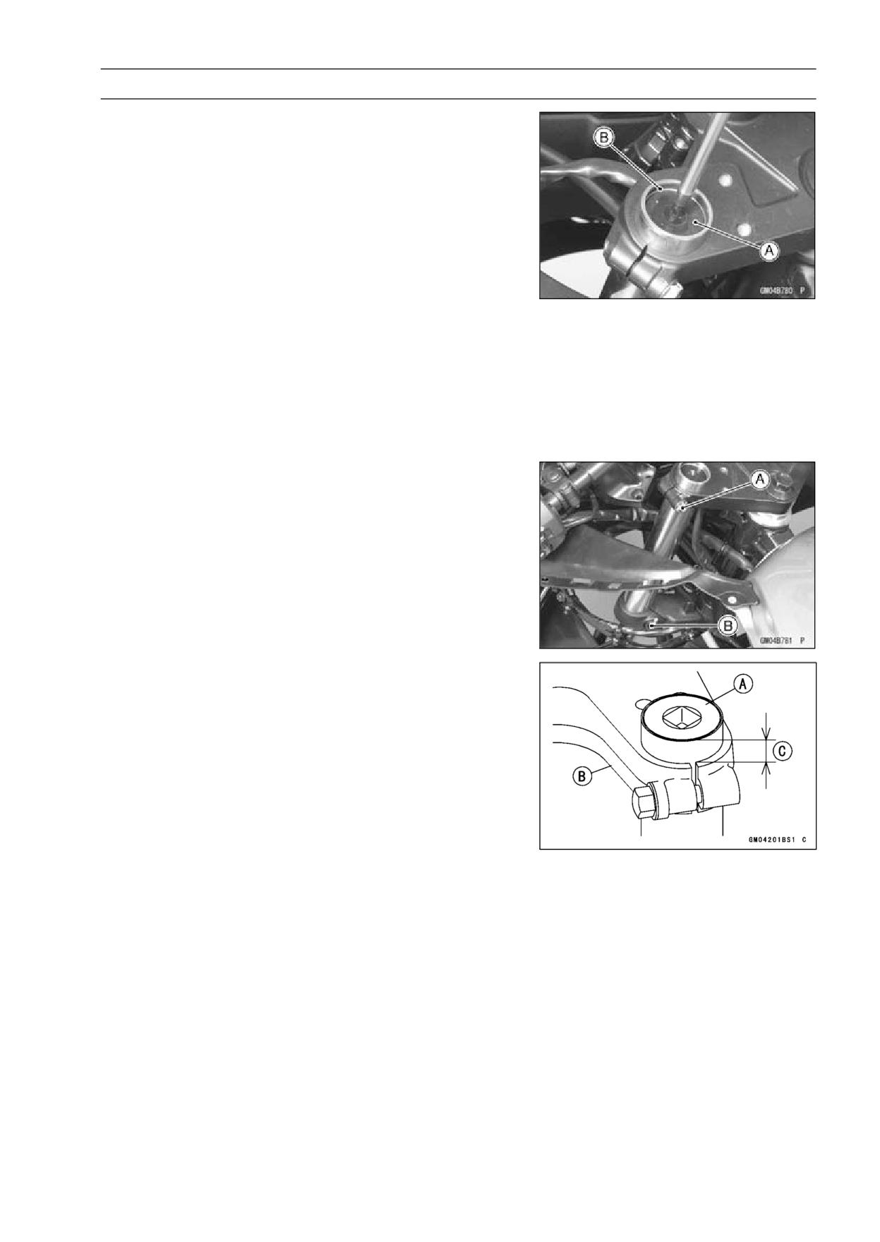
SUSPENSION 13-7
Front Fork
Front Fork Removal
NOTE
○Remove the handlebar holder and remove the fork top
plug [A] beforehand if the fork leg is to be disassembled.
• To remove the top plug, remove the snap ring [B] pushing
down the top plug with the phillips tip screwdriver.
• Remove:
Front Brake Caliper (see Front Caliper Removal in the
Brakes chapter)
Front Wheel (see Front Wheel Removal in the
Wheels/Tires chapter)
Front Fender (see Front Fender Removal in the Frame
chapter)
Lower Fairings (see Lower Fairing Removal in the Frame
chapter)
• Remove the clamps and free the brake hose from the fork
leg.
• Loosen the front fork upper [A] and lower [B] clamp bolts.
• With a twisting motion, remove the fork leg down and out.
Front Fork Installation (each fork leg)
• Insert the fork leg until the inner tube top hit the handlebar
holder lightly, that is, the distance between the inner tube
top [A] and the steering stem head surface [B] is approx-
imate 12 mm (0.47 in.) [C].
Torque - Front Fork Clamp Bolts (Upper):
21 N·m (2.1
kgf·m, 15 ft·lb)
Front Fork Clamp Bolts (Lower):
30 N·m (3.1
kgf·m, 22 ft·lb)
• Route the brake hoses and clamp it to the right fork leg.
• Install:
Handlebar Holder
Front Brake Caliper (see Caliper Installation in the
Brakes chapter)
Front Wheel (see Front Wheel Installation in the
Wheels/Tires chapter)
Front Fender
Lower Fairings (see Lower Fairing Removal in the Frame
chapter)
Torque - Handlebar Holder Mounting Bolts:
25 N·m (2.5
kgf·m, 18 ft·lb)
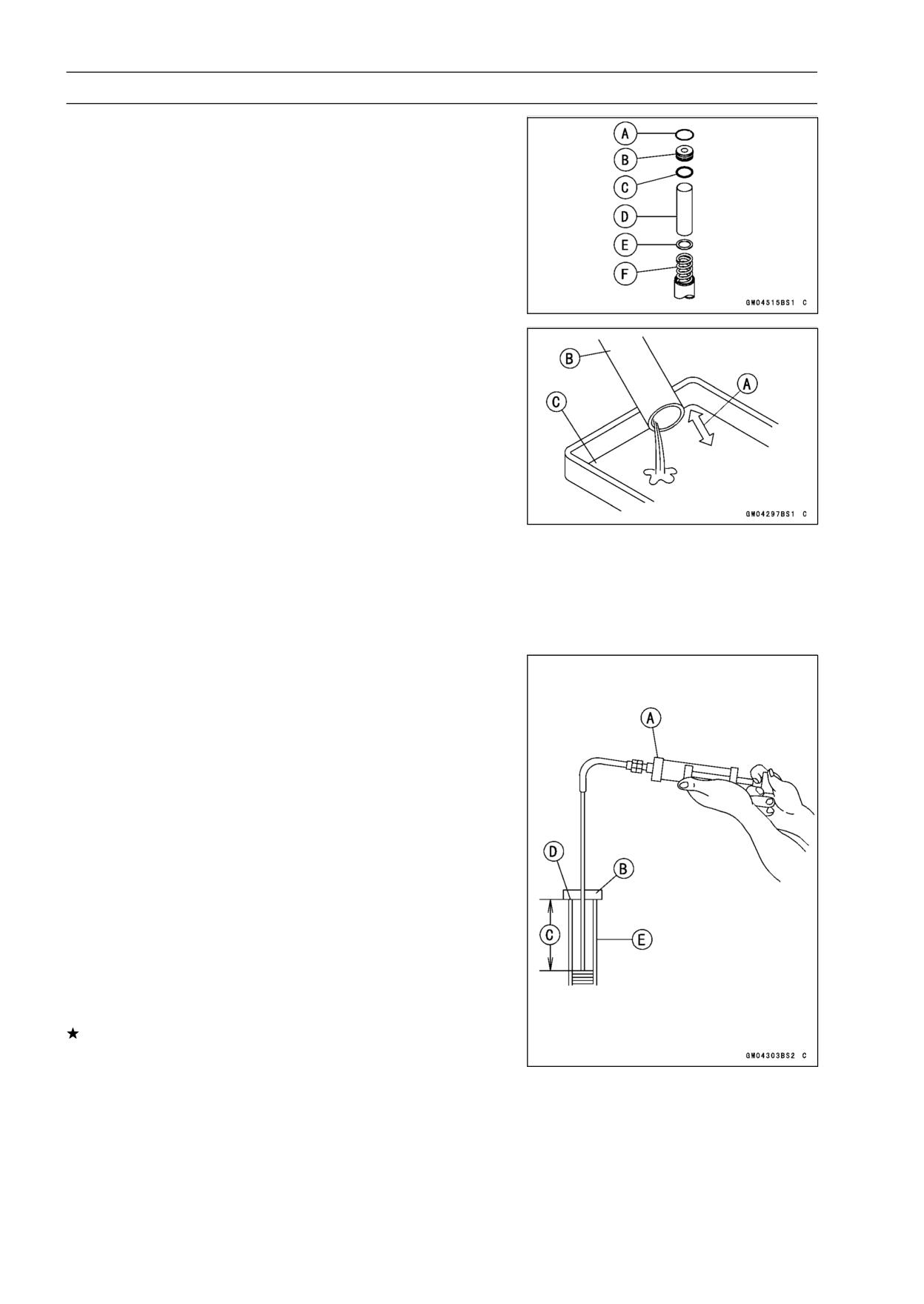
13-8 SUSPENSION
Front Fork
Front Fork Oil Change
• Remove the front fork (see Front Fork Removal).
• Remove:
Snap Ring [A] (see Front Fork Removal)
Top Plug [B] with O-ring [C]
Collar [D]
Fork Spring Seat [E]
Fork Spring [F]
• Compress [A] the fork [B] upside down to draw out the oil
into the suitable container [C].
• Pour in the specified amount of oil.
Fork Oil
Viscosity:
SHOWA SS08 or equivalent
SAE 10W
Amount (Per Side):
When changing oil
310 mL (10.5 US oz.)
After disassembly
360 ±2.5 mL (12.2 ±0.08 US oz.)
and completely dry
NOTE
○Move the outer tube up and down a few times to remove
the air that is trapped in the fork oil in order to stabilize
the oil level.
• Hold the outer tube vertically in a vise and compress the
fork completely.
• Wait until the oil level stabilizes.
• Use the fork oil level gauge [A] to measure the distance
between the top of the inner tube to the oil level.
Special Tool - Fork Oil Level Gauge: 57001-1290
○Set the oil level gauge stopper [B] so that the distance [C]
from the bottom of the stopper to the lower end of the pipe
is the standard oil level distance.
○A correct measurement can not be obtained unless the
level gauge pipe is placed in the center of the inner tube.
Oil Level (fully compressed, without spring)
Standard:
108 ±2 mm (4.3 ±0.08 in.)
○Place the stopper of the level gauge at the top [D] of the
inner tube [E] and pull the handle slowly to draw out the
excess oil from fork into the gauge, thus attaining the stan-
dard level.
If not oil is drawn out, there is not enough oil in the fork.
Pour in some more oil and measure again.
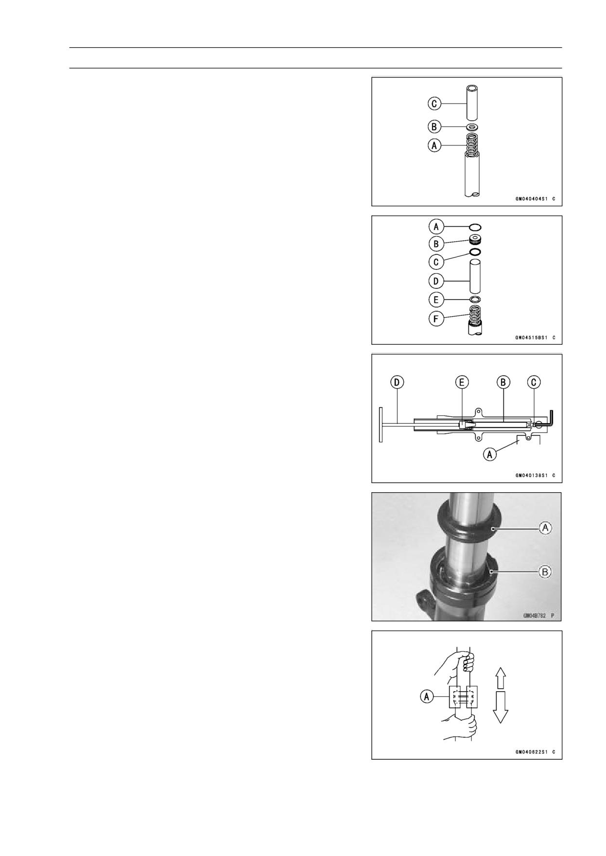
SUSPENSION 13-9
Front Fork
• Repeat the same procedure for adjusting the other fork.
• Install the fork spring [A], fork spring seat [B] and collar
[C].
• Inspect the top plug O-ring and snap ring and replace
them with new ones.
• Install the front fork (see Front Fork Installation).
Front Fork Disassembly
• Remove the front fork (see Front Fork Removal).
• Remove:
Snap Ring [A] (see Front Fork Removal)
Top Plug [B] with O-ring [C]
Collar [D]
Fork Spring Seat [E]
Fork Spring [F]
• Hold the front fork leg horizontally in a vise [A].
• Stop the cylinder unit [B] from turning by using the special
tools.
• Unscrew the front fork bottom Allen bolt [C], and then take
out the bolt and gasket out of the bottom of the outer tube.
Special Tools - Fork Cylinder Holder Handle: 57001-183 [D]
Fork Cylinder Holder Adapter: 57001-1057
[E]
• Take the cylinder unit out of the inner tube.
• Remove the following from the top of the outer tube.
Dust Seal [A]
Retaining Ring [B]
• Use the fork outer tube weight [A] to separate the inner
tube from the outer tube. Holding the inner tube by hand
in a vertical position, pull down the outer tube several
times to pull out the inner tube.
Special Tool - Fork Outer Tube Weight: 57001-1218
• Take out the cylinder base from the outer tube bottom.
• Remove the inner guide bushing from the inner tube.
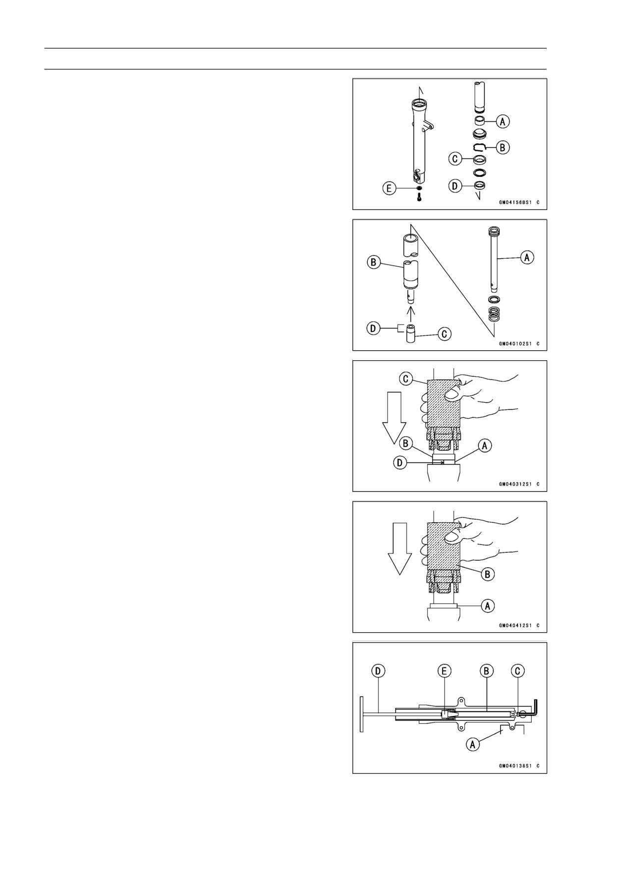
13-10 SUSPENSION
Front Fork
Front Fork Assembly
• Check the top plug O-ring and snap ring and replace them
with new ones if necessary.
• Replace the following parts with new ones.
Inner Guide Bushing [A]
Retaining Ring [B]
Oil Seal [C]
Outer Guide Bushing [D]
Bottom Allen Bolt Gasket [E]
• Put the cylinder unit [A] with the spring into the inner tube
[B] protruding from the inner tube, and install the cylinder
base [C] onto the bottom end of the cylinder unit.
○Install the cylinder base with the tapered end [D] facing
upward.
• Install the inner tube, cylinder unit, and cylinder base as
a set into the outer tube.
• Install the new guide bushing [A] with a use one [B] on it
by tapping the use one with the fork oil seal driver [C].
○The split [D] of the bushing should face toward the side of
the vehicle.
Special Tool - Front Fork Oil Seal Driver: 57001-1219
• Apply molybdenum disulfide grease to the oil seal lips and
install the washer and the oil seal [A] into the outer tube.
Special Tool - Front Fork Oil Seal Driver: 57001-1219 [B]
• Install the retaining ring on the outer tube.
• Install a new bottom Allen bolt gasket.
• Apply a non-permanent locking agent to the threads of the
bottom Allen bolt and screw the Allen bolt into the bottom
of the outer tube.
• Hold the outer tube in a vise [A], hold the cylinder unit [B]
with the special tools, then tighten the Allen bolt [C].
○Apply a non-permanent locking agent to the front fork bot-
tom Allen bolt.
Special Tools - Fork Cylinder Holder Handle: 57001-183 [D]
Fork Cylinder Holder Adapter: 57001-1057
[E]
Torque - Front Fork Bottom Allen Bolt: 20 N·m (2.0 kgf·m,
15 ft·lb)
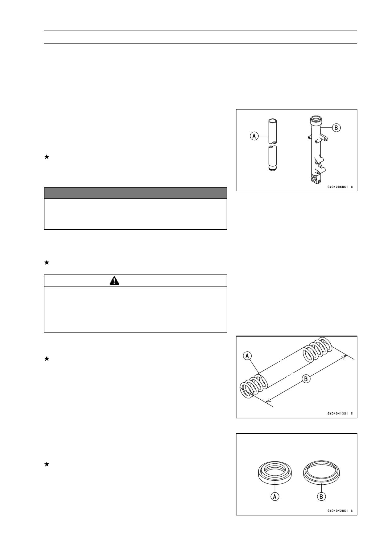
SUSPENSION 13-11
Front Fork
• Fill with the specified type of oil and install the parts re-
moved (see Fork Oil change).
• Install the dust seals.
Fork Oil:
KAYABA SS-8 or equivalent
Capacity (per
360 ±2.5 mL (12.2 ±0.08 US oz), (after
one unit):
fork disassembly and completely dry)
Inner Tube/Outer Tube Inspection
• Visually inspect the inner tube [A] and repair any damage.
• Nick or rust damage can sometimes be repaired by using
a wet-stone to remove sharp edges or raised areas which
cause seal damage.
If the damage is not repairable, replace the inner tube.
Since damage to the inner tube damages the oil seal,
replace the oil seal whenever the inner tube is repaired
or replace.
NOTICE
If the inner tube is badly bent or creased, replace
it.
Excessive bending, followed by subsequent
straightening, can weaken the inner tube.
• Temporarily assemble the inner tube and outer tube [B],
and pump them back and forth manually to check for
smooth operation.
If it does not operate smoothly, replace both the inner tube
and the outer tube.
WARNING
A straightened inner or outer fork tube may fall in
use, possibly causing an accident resulting in seri-
ous injury or death. Replace a badly bent or dam-
aged inner or outer tube and inspect the other tube
carefully before reusing it.
Fork Spring Inspection
• Measure the free length [B] of the fork spring [A].
If the spring of either fork leg is shorter than the service
limit, it must be replaced. If the length of the replacement
spring and that of the remaining spring vary greatly, the
remaining spring should also be replaced in order to keep
the fork legs balanced for motorcycle stability.
Fork Spring Free Length
Standard:
420.5 mm (16.6 in.)
Service Limit:
412 mm (16.2 in.)
Oil Seal/Dust Seal Inspection
• Inspect the oil seal [A] and dust seal [B] for any signs of
deterioration or damage.
Replace it if necessary.
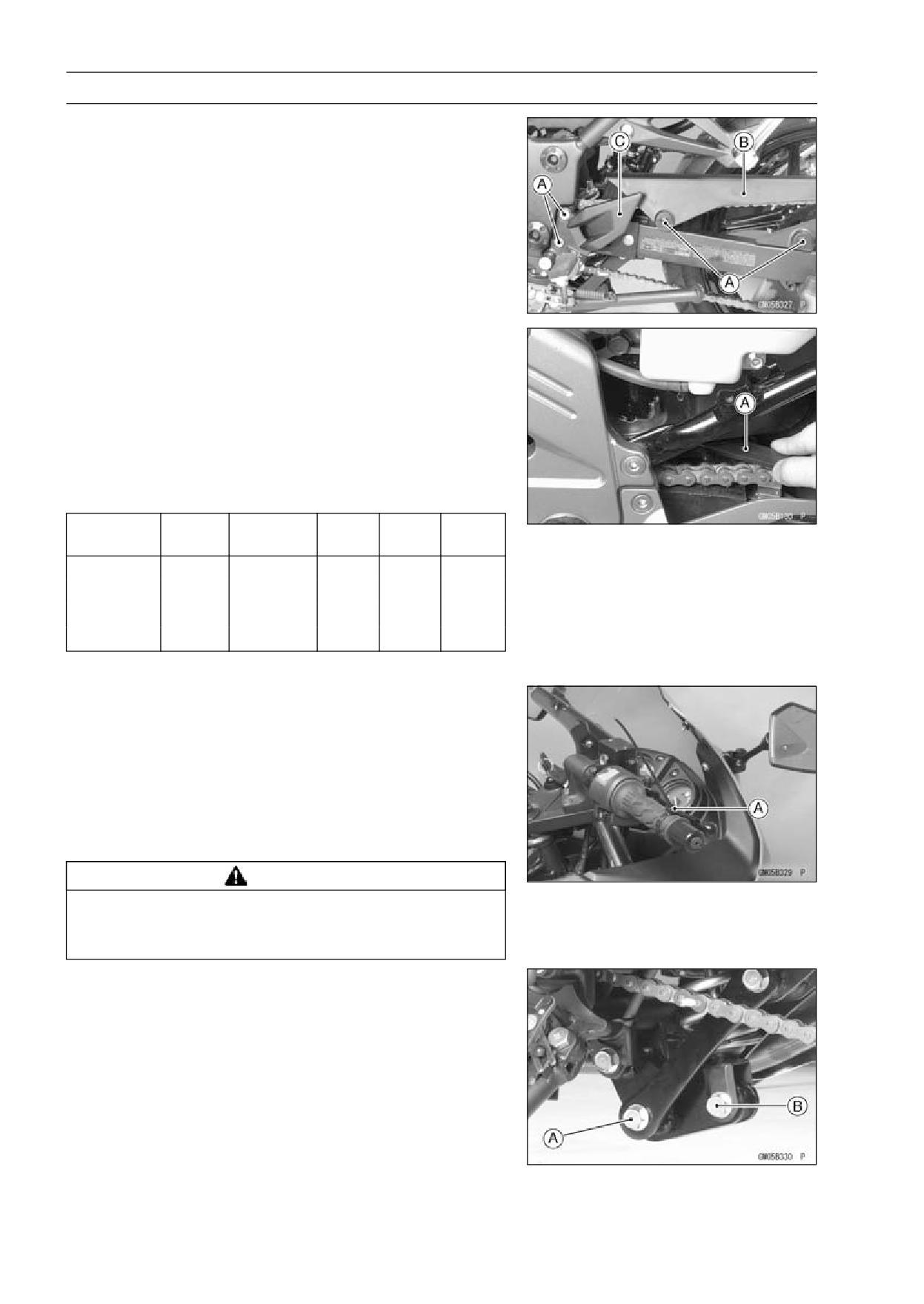
13-12 SUSPENSION
Rear Shock Absorber
Spring Preload Adjustment
• Remove the bolts [A], chain cover [B] and left foot guard
[C] to turn the wrench.
• Using the steering stem nut wrench [A], turn the adjusting
nut to adjust the spring preload.
Special Tool - Steering Stem Nut Wrench: 57001-1100
• The spring preload can be left soft for average riding. But
it should be adjusted harder for high speed riding or riding
with a passenger. If the spring action feels too soft or too
stiff, adjust it in accordance with the following table.
Spring Preload Adjustment
Adjuster
Spring
Setting
Load
Road
Speed
Position
Force
1
Weak
Soft
Light
Good
Low
↑
↑
↑
↑
↑
↑
↓
↓
↓
↓
↓
↓
5
Strong
Hard
Heavy
Bad
High
• The standard adjuster setting is 1 step.
Rear Shock Absorber Removal
• Remove the lower fairings (see Lower Fairing in the
Frame chapter).
• Raise the rear wheel off the ground with jack.
Special Tools - Jack: 57001-1238
Jack Attachment: 57001-1608
• Squeeze the brake lever slowly and hold it with the band
[A].
WARNING
Be sure to hold the front brake when removing the
shock absorber, or the motorcycle may fall over. It
could cause an accident and injury.
• Remove:
Tie-rod Lower and Bolt [A]
Rear Shock Absorber Nuts and Bolts [B]
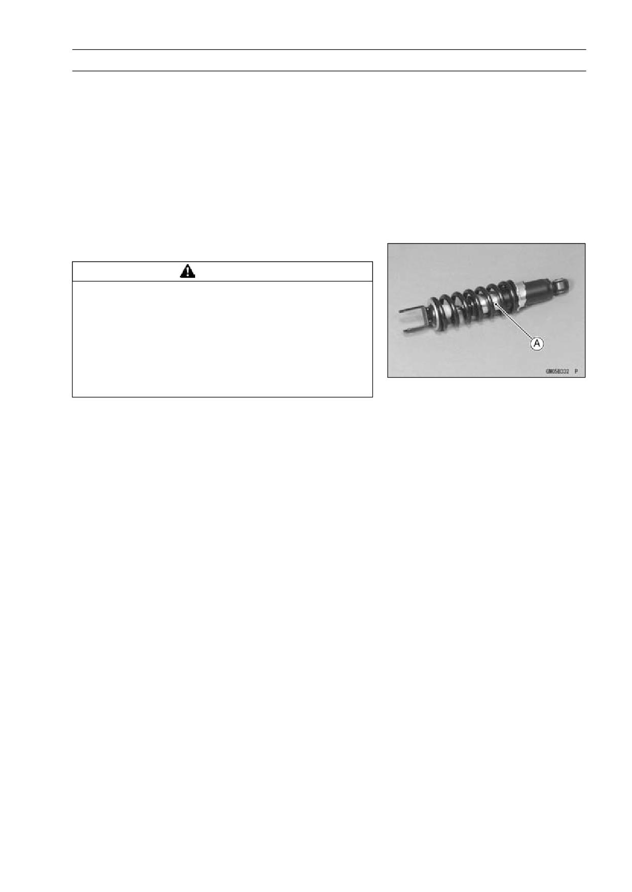
SUSPENSION 13-13
Rear Shock Absorber
Rear Shock Absorber Installation
• Install the rear shock absorber.
• Replace:
Rear Shock Absorber Mounting Nuts
Tie-rod Nuts
• Tighten the tie-rod lower bolt and nut.
Torque - Rear Shock Absorber Mounting Nuts: 59 N·m (6.0
kgf·m, 44 ft·lb)
Tie-rod Nut (Lower): 59 N·m (6.0 kgf·m, 44 ft·lb)
• Adjust the rear shock absorber spring preload in response
to riding condition (see Spring Preload Adjustment).
Rear Shock Absorber Scrapping
WARNING
Since the rear shock absorber contains nitrogen
gas, do not incinerate the rear shock absorber with-
out first releasing the gas or it may explode.
Before a rear shock absorber is scrapped, drill a
hole at the point [A] shown to release the nitrogen
gas completely. Wear safety glasses when drilling
the hole, as the gas may below out bits of drilled
metal when the hole opens.
• Drill the cylinder [A] of the shock absorber using about 2
mm (0.08 in.) drill bit.
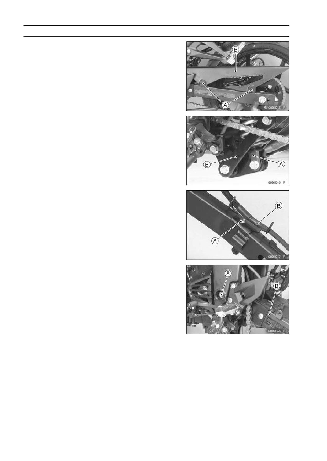
13-14 SUSPENSION
Swingarm
Swingarm Removal
• Remove the lower fairings (see Lower Fairing Removal in
the Frame chapter).
• Remove the bolts [A] and the chain cover [B].
• Raise the rear wheel off the ground with jack.
Special Tools - Jack: 57001-1238
Jack Attachment: 57001-1608
• Remove:
Rear Wheel (see Rear Wheel Removal in the
Wheels/Tire chapter)
Rear Shock Absorber [A] (see Rear Shock Absorber Re-
moval)
Tie-rod [B] (see Tie-rod Removal)
• Remove:
Brake Hose Clamp Bolt [A]
Bracket [B] with Brake Hose
• Remove the swingarm pivot nut [A] and shaft, remove the
swingarm [B].
Swingarm Installation
• Installation is the reverse of removal.
○Apply grease to the lip of oil seals.
○Be sure to install the oil seal and collar to swingarm.
• Tighten the swingarm pivot nut.
Torque - Swingarm Pivot Nut: 98 N·m (10.0 kgf·m, 72 ft·lb)
• Install the removed parts.
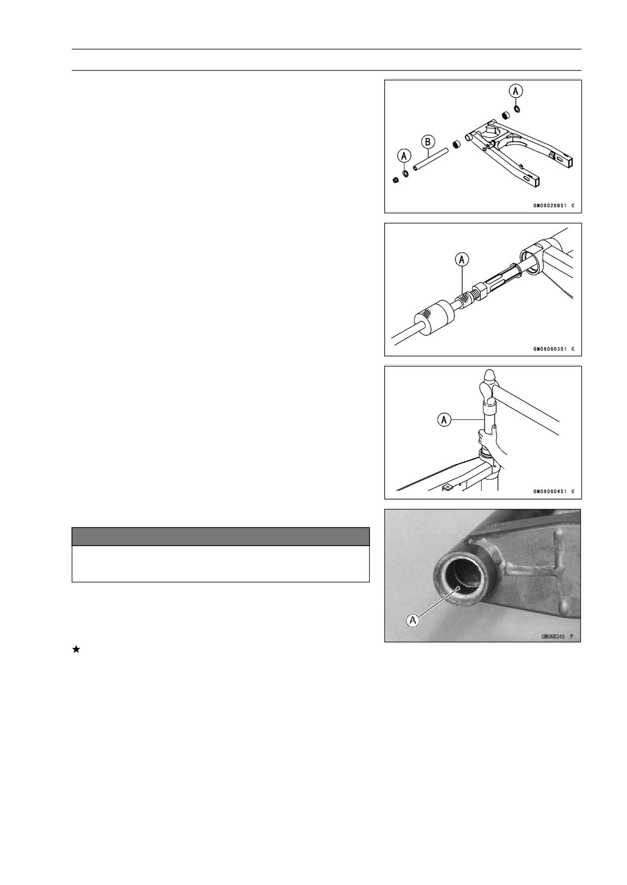
SUSPENSION 13-15
Swingarm
Swingarm Bearing Removal
• Remove:
Swingarm (see Swingarm Removal)
Grease Seal [A]
Sleeve [B]
Special Tool - Inside Circlip Pliers: 57001-143
• Remove the needle bearing.
Special Tool - Oil Seal & Bearing Remover: 57001-1058 [A]
Swingarm Bearing Installation
• Apply plenty of grease to the needle bearings.
• Install the needle bearings so that the manufacturer’s
marks faces out.
Special Tool - Bearing Driver Set: 57001-1129 [A]
Swingarm Bearing, Sleeve Inspection
NOTICE
Do not remove the bearings for inspection. Re-
moval many damage them.
• The rollers in a needle bearing [A] normally wear very lit-
tle, and wear is difficult to measure. Instead of measuring,
inspect the bearing in the swingarm for abrasion, color
change, or other damage.
If there is any doubt as to the condition of any of the nee-
dle bearings or sleeve, replace the sleeve, and needle
bearings as a set.
13-16 SUSPENSION
Swingarm
Swingarm Lubrication
• Lubricate the swingarm needle bearings [A] according to
the Periodic Maintenance Chart. They are normal for a
small amount of grease to seep out around the grease
seals.
○If the swingarm pivots is disassembled, wipe all the old
grease off the bearings, sleeves, and grease seals, then
grease them.
Chain Guide Inspection
• Refer to the Chain Guide Wear Inspection in the Periodic
Maintenance chapter (see Chain Guide Wear Inspection
in the Periodic Maintenance chapter).