Kawasaki Ninja 250R Motorcycle. Service Manual (2007) - page 2
FUEL SYSTEM 3-29
Air Cleaner
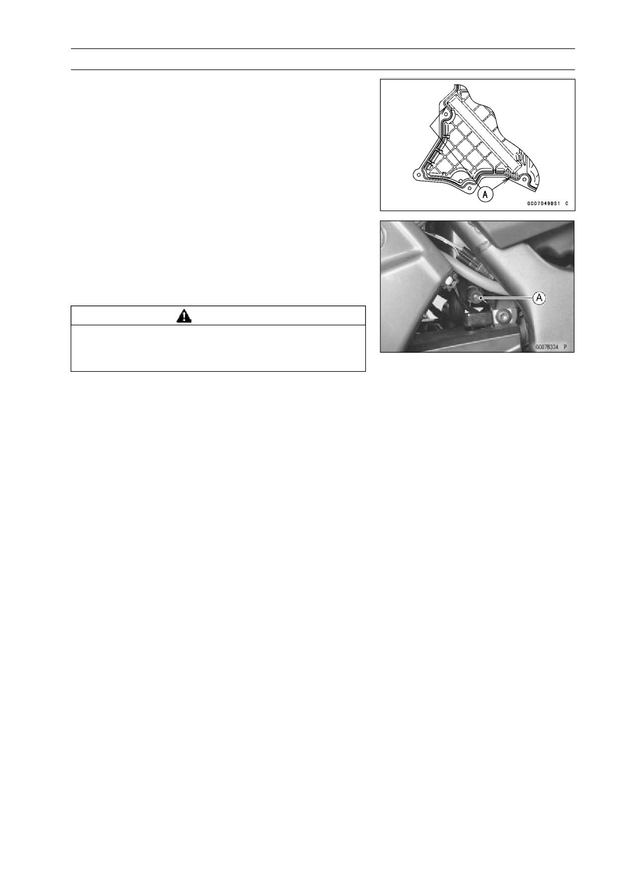
• Apply a bonding agent to the slash portion [A] of the air
cleaner housing.
Oil Draining
• Remove the drain cap [A] at the lower end of the air
cleaner housing and drain water or oil accumulates in the
air cleaner housing.
• Be sure to install the cap firmly, or the air is drawn in
through it.
WARNING
Oil on tires will make them slippery and can cause
an accident and injury. Be sure to reinstall the cap
in the air cleaner housing after draining.
3-30 FUEL SYSTEM
Fuel Tank
Fuel Tank Removal
WARNING
Gasoline is extremely flammable and can be ex-
plosive under certain conditions, creating the
potential for serious burns. Make sure the area is
well-ventilated and free from any source of flame
or sparks; this includes any appliance with a pilot
light. Do not smoke. Turn the ignition switch OFF.
Be prepared for fuel spillage; any spilled fuel must
be completely wiped up immediately.
• Remove the side covers (see Side Covers Removal in the
Frame chapter).
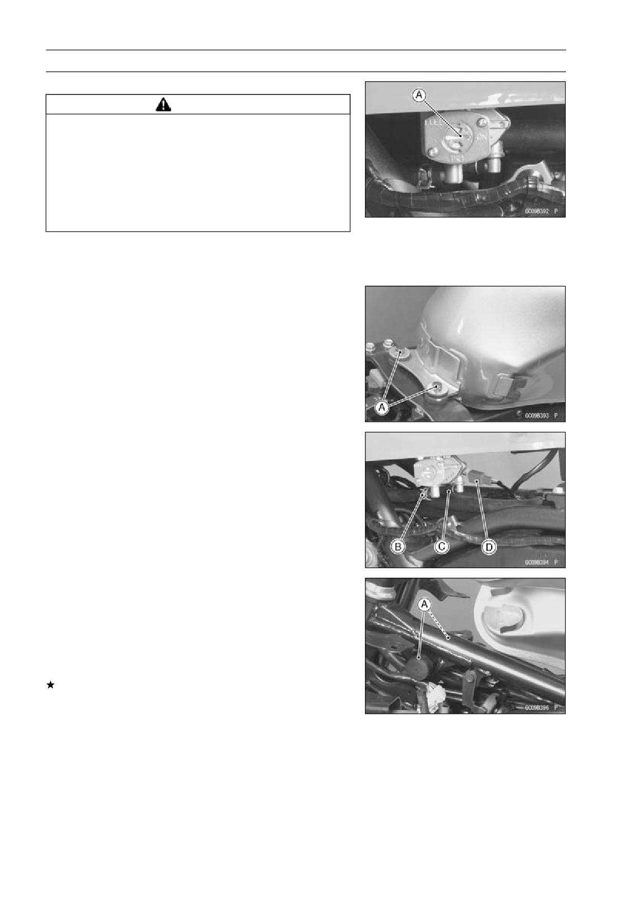
• Turn the fuel tap position to the ON [A] position.
• Remove:
Front Seat (see Front Seat Removal in the Frame chap-
ter)
Lower Fairings (see Lower Fairing Removal in the Frame
chapter)
Fuel Tank Mounting Bolts [A]
Fuel Hose [B]
Vacuum Hose [C]
Fuel Level Sensor Connector [D]
Fuel Tank
• Drain the fuel tank if necessary.
○Arrange a suitable container under the fuel tap.
○Turn the fuel tap position to the PRI position to drain the
fuel into the container.
Fuel Tank Installation
• Read the above WARNING mentioned in Fuel Tank Re-
moval.
• Route the hose correctly.
• Be sure the hoses are clamped securely to prevent fuel
leaks.
• Be sure the rubber dampers [A] are in position.
If any dampers is damaged or deteriorated, replace it.
FUEL SYSTEM 3-31
Fuel Tank
Fuel Tap Removal
WARNING
Gasoline is extremely flammable and can be ex-
plosive under certain conditions. Turn the ignition
switch OFF. Do not smoke. Make sure the area is
well-ventilated and free from any source of flame
or sparks; this includes any appliance with a pilot
light.
• Remove the fuel tank (see Fuel Tank Removal).
• Drain the fuel into a suitable container.
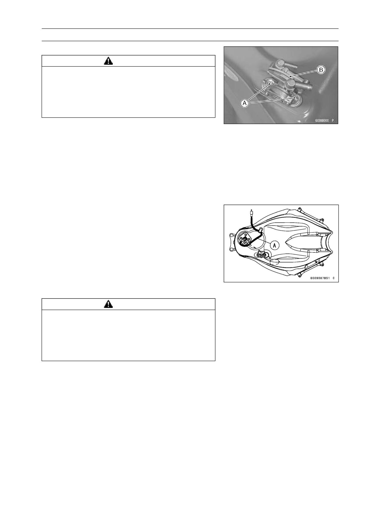
• Remove the bolts [A] and take out the fuel tap [B].
Fuel Tap Installation
• Fuel tap installation is the reverse of removal. Note the
following.
Torque - Fuel Tap Mounting Bolts: 2.5 N·m (0.25 kgf·m, 22
in·lb)
• Be sure to clamp the fuel hose to the tap to prevent leaks.
• Be sure the fuel level sensor leads [A] are routed as
shown.
Fuel Tank and Tap Cleaning
WARNING
Gasoline and low-flash point solvents can be
flammable and/or explosive and cause severe
burns. Clean the tank in a well-ventilated area, and
take care that there are no sparks or flame any-
where near the working area. Do not use gasoline
or low-flash point solvents to clean the tank.
• Remove the fuel tank and drain it.
• Pour some high flash-point solvent into the fuel tank and
shake the tank to remove dirt and fuel deposits.
• Pour high flash-point solvent.
• Pour the solvent out of the tank.
• Remove the fuel tap from the tank by taking out the bolts.
• Clean the fuel tap in a high flash-point solvent.
• Pour high flash-point solvent through the tap in ON and
PRI positions.
• Dry the tank and tap with compressed air.
• Install the tap in the tank.
• Install the fuel tank (see Fuel Tank Installation).
3-32 FUEL SYSTEM
Fuel Tank
Fuel Tap Inspection
• Remove the fuel tap (see Fuel Tap Removal).
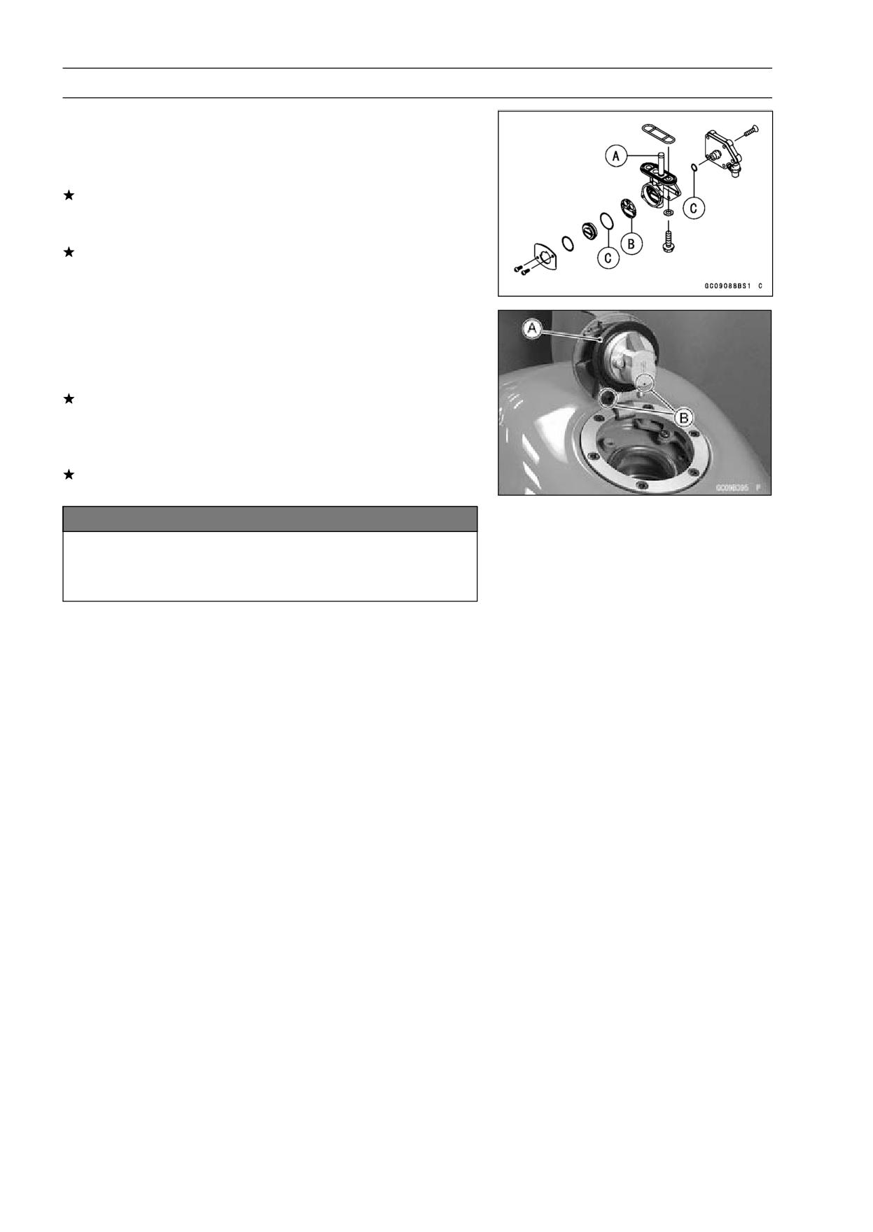
• Check the fuel tap filter screen [A] for any breaks or dete-
rioration.
If the fuel tap screens have any breaks or are deterio-
rated, they may allow dirt to reach the carburetor, causing
poor running. Replace the fuel tap.
If the fuel tap leaks, or allows fuel to flow when it is at
ON or PRI without engine running, replace the damaged
gasket [B] or O-rings [C].
Fuel Tank and Cap Inspection
• Open the tank cap.
• Visually inspect the gaskets [A] on the tank cap for any
damage.
Replace the gaskets if they are damaged.
• Remove the drain pipes and check to see if the pipes in
the tank do not clogged up. Check the tank cap breather
also.
If they are clogged, remove the tank and drain it, and then
blow the breather free with compressed air.
NOTICE
Do not apply compressed air to the air vent holes
[B] in the tank cap. This could cause damage and
clogging of the labyrinth in the cap.
FUEL SYSTEM 3-33
Evaporative Emission Control System (CAL Model)
Separator Operation Test
WARNING
Gasoline is extremely flammable and can be ex-
plosive under certain conditions. Do not smoke.
Turn the ignition switch OFF. Make sure the area is
well-ventilated and free from any source of flame
or sparks; this includes any appliance with a pilot
light.
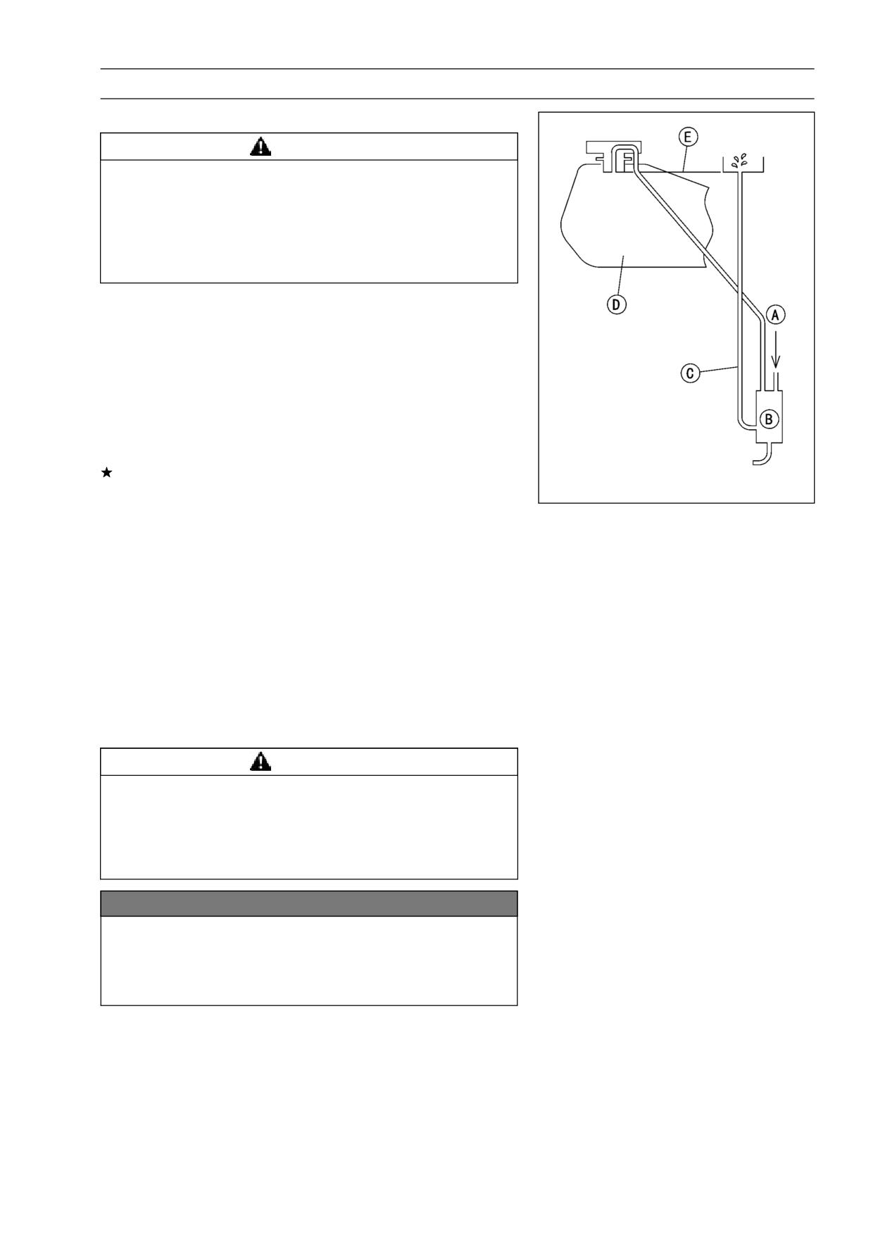
• Connect the hoses to the separator, and install the sepa-
rator on the motorcycle.
• Disconnect the breather hose from the separator, and in-
ject about 20 mL (0.68 US oz.) of gasoline [A] into the
separator [B] through the hose fitting.
• Disconnect the fuel return hose [C] from the fuel tank [D].
• Run the open end of the return hose into the container
and hold it level with the tank top [E].
• Start the engine, and let it idle.
If the gasoline in the separator comes out of the hose, the
separator works well. If it does not, replace the separator
with a new one.
Canister Inspection
• Refer to the Evaporative Emission Control System In-
spection in the Periodic Maintenance chapter.
The Evaporative Emission Control System routes fuel va-
pors from the fuel system into the running engine or stores
the vapors in a canister when the engine is stopped. Al-
though no adjustments are required, a thorough visual in-
spection must be made at the intervals specified by the Pe-
riodic Maintenance Chart.
Parts Removal/Installation
WARNING
Gasoline is extremely flammable and can be explo-
sive under certain conditions. Make sure the area
is well-ventilated and free from any source of flame
or sparks; this includes any appliance with a pilot
light. Do not smoke. Turn the ignition switch OFF.
NOTICE
If gasoline, solvent, water or any other liquid enters
the canister, the canister’s vapor absorbing capac-
ity is greatly reduced. If the canister does become
contaminated, replace it with a new one.
• To prevent the gasoline from flowing into or out of the
canister, hold the separator perpendicular to the ground.
• Connect the hoses according to the see Cable, Wire, and
Hose Routing section in the Appendix chapter. Make sure
they do not get pinched or kinked.
Hose Inspection
• Refer to the Evaporative Emission Control System In-
spection in the Periodic Maintenance chapter.
COOLING SYSTEM 4-1
Cooling System
Table of Contents
Exploded View
4-2
Specifications
4-4
Sealant
4-5
Coolant Flow Chart
4-6
Coolant
4-8
Coolant Deterioration Inspection
4-8
4
Coolant Level Inspection
4-8
Coolant Draining
4-8
Coolant Filling
4-8
Pressure Testing
4-8
Cooling System Flushing
4-9
Water Pump
4-10
Pump Cover Removal
4-10
Pump Cover Installation
4-10
Water Pump Removal
4-10
Water Pump Installation
4-10
Pump Impeller Inspection
4-11
Radiator, Radiator Fan
4-12
Radiator and Radiator Fan Removal
4-12
Radiator Inspection
4-13
Radiator Cleaning
4-13
Radiator Cap Inspection
4-13
Radiator Filler Neck Inspection
4-14
Thermostat
4-15
Thermostat Removal
4-15
Thermostat Installation
4-15
Thermostat Housing Removal
4-15
Thermostat Housing Installation Note
4-15
Thermostat Inspection
4-16
Hoses and Pipes
4-17
Hose Installation
4-17
Hose Inspection
4-17
Radiator Fan Switch, Water Temperature Switch
4-18
Radiator Fan Switch, Water Temperature Switch Removal
4-18
Radiator Fan Switch, Water Temperature Switch Installation
4-18
Radiator Fan Switch, Water Temperature Switch Inspection
4-18
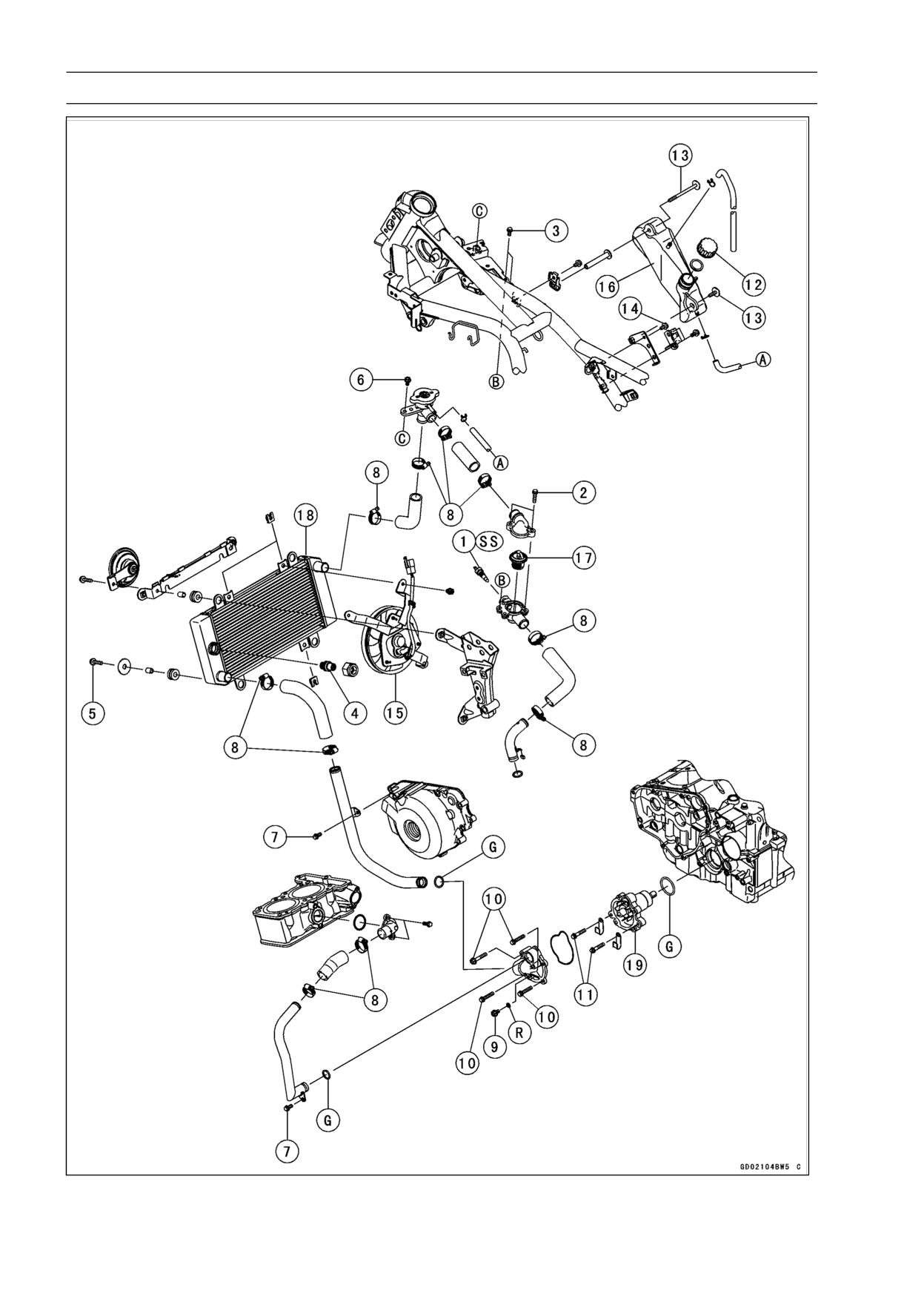
4-2 COOLING SYSTEM
Exploded View
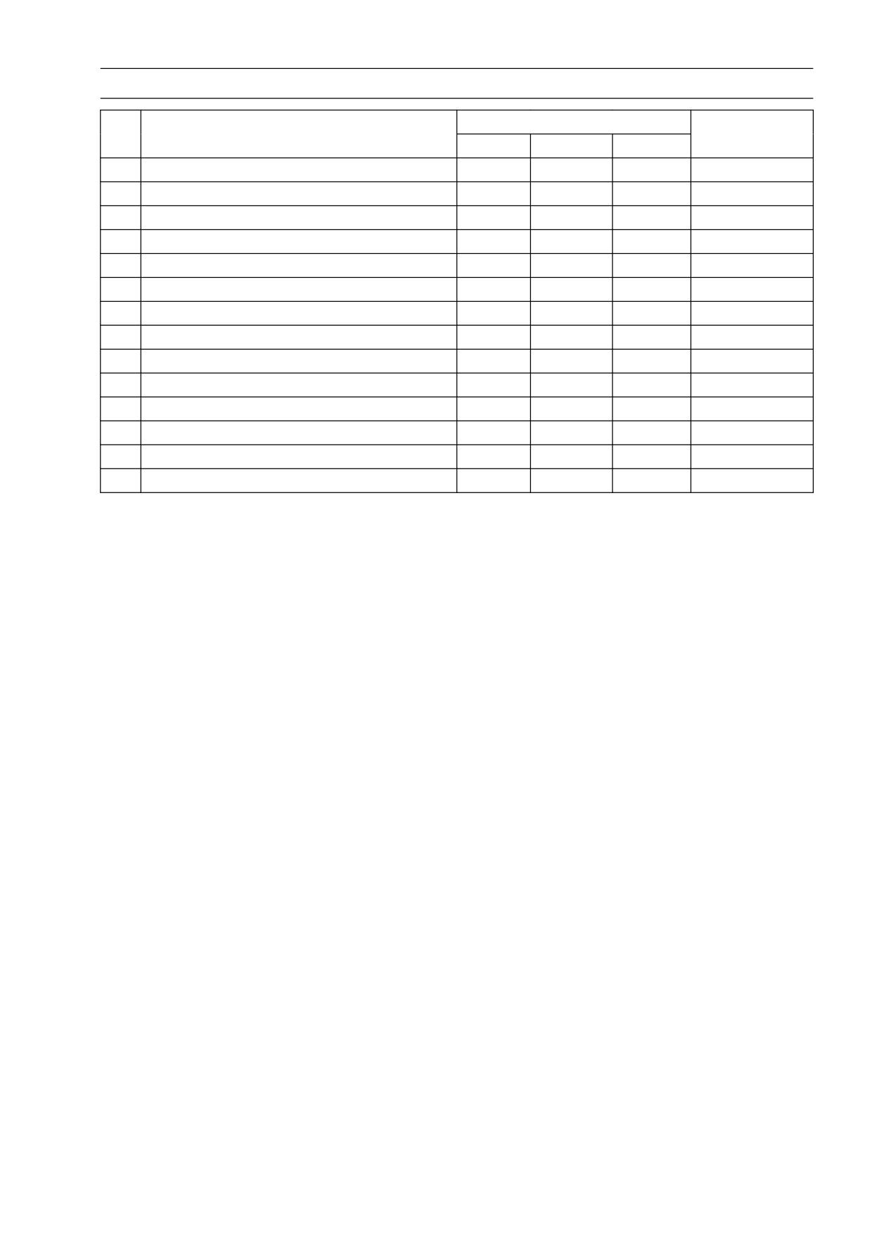
COOLING SYSTEM 4-3
Exploded View
Torque
No.
Fastener
Remarks
N·m
kgf·m
ft·lb
1
Water Temperature Switch
7.5
0.76
66 in·lb
SS
2
Thermostat Cover Bolts
9.8
1.0
87 in·lb
3
Thermostat Housing Mounting Bolts
9.8
1.0
87 in·lb
4
Radiator Fan Switch
23.5
2.4
17
5
Radiator Bolts
9.8
1.0
87
in·lb
6
Radiator Cap Bracket Bolt
9.8
1.0
87
in·lb
7
Water Pipe Bolts
9.8
1.0
87
in·lb
8
Water Hose Clamp Screws
3.0
0.31
27
in·lb
9
Drain Bolt
9.8
1.0
87
in·lb
10
Water Pump Cover Bolts
9.8
1.0
87
in·lb
11
Water Pump Bolts
9.8
1.0
87
in·lb
12
Reserve Tank Cap
-
-
-
Hand-Tighten
13
Reserve Tank Bolts
9.8
1.0
87
in·lb
14
Reserve Tank Bracket Bolt
9.8
1.0
87
in·lb
15. Radiator Fan
16. Reserve Tank
17. Thermostat
18. Radiator
19. Water Pump
G: Apply grease.
R: Replacement Parts
SS: Apply silicone sealant to the threads.
4-4 COOLING SYSTEM
Specifications
Item
Standard
Coolant
Type
Permanent type of antifreeze (soft water and ethylene glycol plus
corrosion and rust inhibitor chemicals for aluminum engines and
radiators)
Collar
Green
Mixed Ratio
Soft water 50%, coolant 50%
Freezing Point
-35°C (-31°F)
Total Capacity
1.5 L (1.59 US qt)
Radiator
Radiator Cap Relief Pressure
93 ∼ 123 kPa (0.95 ∼ 1.25 kgf/cm², 13 ∼ 18 psi)
Thermostat
Valve Opening Temperature
63.5 ∼ 66.5°C (146 ∼ 152°F)
Valve Full Opening Lift
More than 6 mm (0.24 in.) @80°C (176°F)
COOLING SYSTEM 4-5
Sealant
Liquid Gasket, TB1211:
56019-120
4-6 COOLING SYSTEM
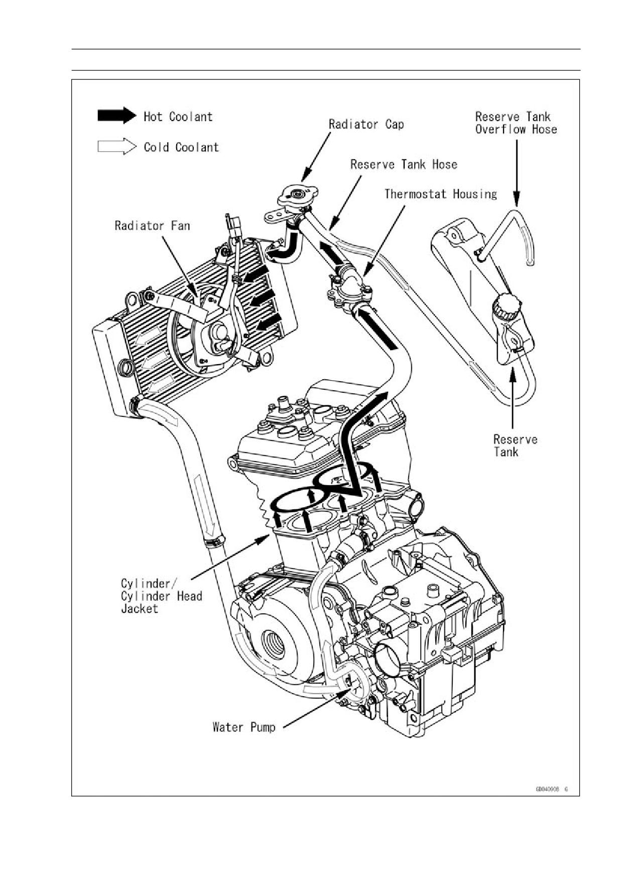
Coolant Flow Chart
Permanent type antifreeze is used as a coolant to protect the cooling system from rust and corrosion.
When the engine starts, the water pump turns and the coolant circulates.
The thermostat is a wax pellet type which opens or closes with coolant temperature changes. The
thermostat continuously changes its valve opening to keep the coolant temperature at the proper level.
When coolant temperature is below 63.5 ∼ 66.5°C (146 ∼ 152°F), the thermostat closes so that the
coolant flow is restricted through the air bleeder hole, causing the engine to warm up more quickly.
When coolant temperature is more than 63.5 ∼ 66.5°C (146 ∼ 152°F), the thermostat opens and the
coolant flows.
When the coolant temperature goes up beyond 96 ∼ 100°C (205 ∼ 212°F), the radiator fan switch
conducts to operate the radiator fan. The radiator fan draws air through the radiator core when there
is not sufficient air flow such as at low speeds. This increases up the cooling action of the radiator.
When the temperature is below 91°C (196°F), the fan switch opens and the radiator fan stops.
In this way, this system controls the engine temperature within narrow limits where the engine op-
erates most efficiently even if the engine load varies.
The system is pressurized by the radiator cap to suppress boiling and the resultant air bubbles
which can cause engine overheating. As the engine warms up, the coolant in the radiator and the
water jacket expands. The excess coolant flows through the radiator cap and hose to the reserve tank
to be stored there temporarily. Conversely, as the engine cools down, the coolant in the radiator and
the water jacket contracts, and the stored coolant flows back to the radiator from the reserve tank.
The radiator cap has two valves. One is a pressure valve which holds the pressure in the system
when the engine is running. When the pressure exceeds 93 ∼ 123 kPa (0.95 ∼ 1.25 kgf/cm², 13 ∼ 18
psi) the pressure valve opens and releases the pressure to the reserve tank. As soon as pressure
escapes, the valve closes, and keeps the pressure at 93 ∼ 123 kPa (0.95 ∼ 1.25 kgf/cm², 13 ∼ 18 psi).
When the engine cools down, another small valve (vacuum valve) in the cap opens. As the coolant
cools, the coolant contracts to form a vacuum in the system. The vacuum valve opens and allows the
coolant from the reserve tank to enter the radiator.
COOLING SYSTEM 4-7
Coolant Flow Chart
4-8 COOLING SYSTEM
Coolant
Coolant Deterioration Inspection
• Remove the right lower fairing (see Lower Fairing Re-
moval in the Frame chapter).
• Visually inspect the coolant in the reserve tank.
If whitish cotton-like wafts are observed, aluminum parts
in the cooling system are corroded. If the coolant is
brown, iron or steel parts are rusting. In either case, flush
the cooling system.
If the coolant gives off an abnormal smell, check for a
cooling system leak. It may be caused by exhaust gas
leaking into the cooling system.
Coolant Level Inspection
• Refer to Coolant Level Inspection in the Periodic Mainte-
nance chapter (see Coolant Level Inspection in the Peri-
odic Maintenance chapter).
Coolant Draining
• Refer to Coolant Change in the Periodic Maintenance
chapter (see Coolant Change in the Periodic Mainte-
nance chapter).
Coolant Filling
• Refer to Coolant Change in the Periodic Maintenance
chapter (see Coolant Change in the Periodic Mainte-
nance chapter).
Pressure Testing
• Remove:
Right Lower Fairing (see Lower Fairing Removal in the
Frame chapter)
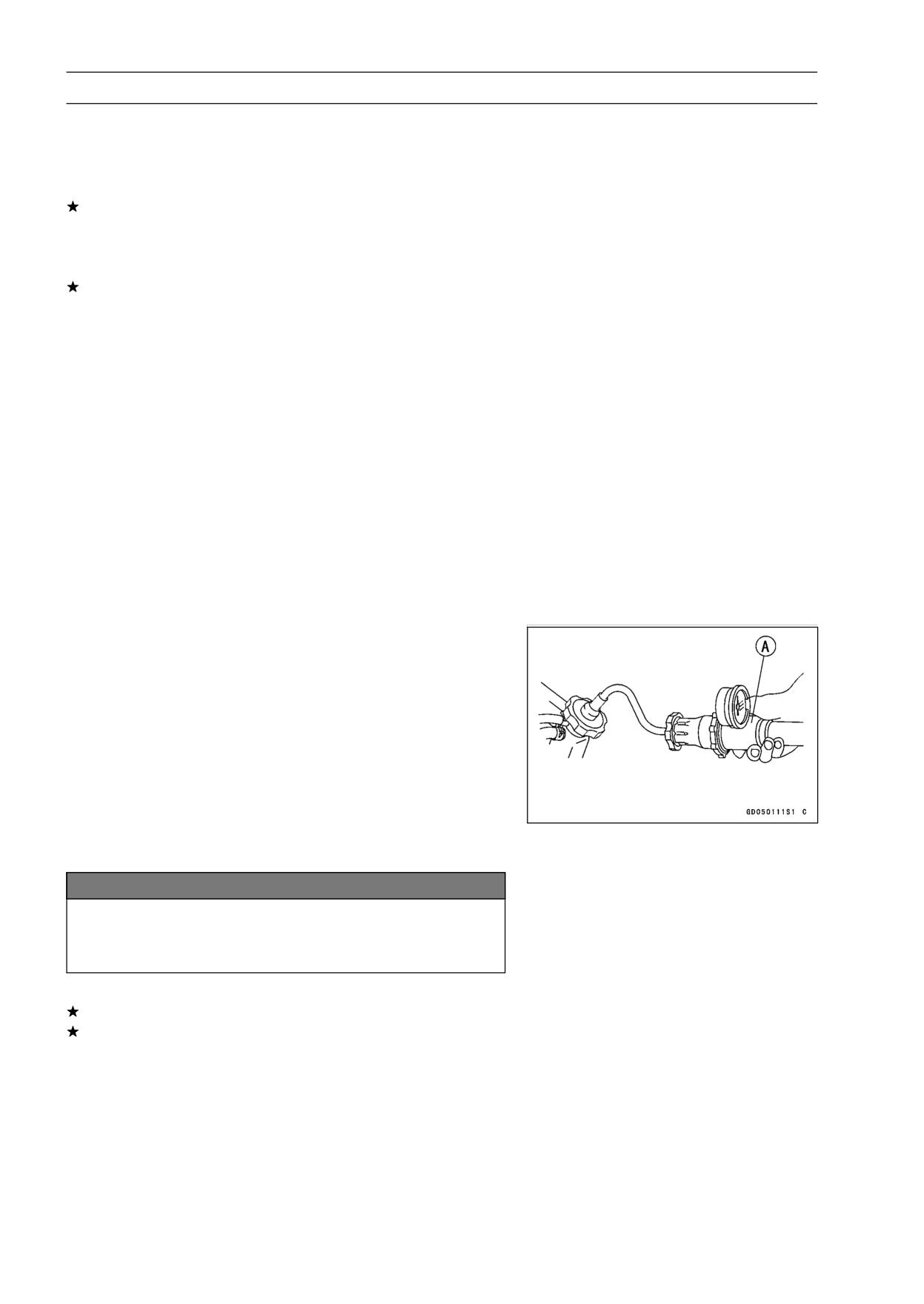
• Remove the radiator cap, and install a cooling system
pressure tester [A] on the filler neck.
NOTE
○Wet the cap sealing surfaces with water or coolant to
prevent pressure leaks.
• Build up pressure in the system carefully until the pres-
sure reaches 123 kPa (1.25 kgf/cm², 18 psi).
NOTICE
During pressure testing, do not exceed the pres-
sure for which the system is designed. The maxi-
mum pressure is 123 kPa (1.25 kgf/cm², 18 psi).
• Watch the gauge for at least 6 seconds.
If the pressure holds steady, the system is all right.
If the pressure drops and no external source is found,
check for internal leaks. Droplets in the engine oil indicate
internal leakage. Check the cylinder head gasket and the
water pump.
• Remove the pressure tester, replenish the coolant, and
install the radiator cap.
COOLING SYSTEM 4-9
Coolant
Cooling System Flushing
Over a period of time, the cooling system accumulates
rust, scale, and lime in the water jacket and radiator. When
this accumulation is suspected or observed, flush the cool-
ing system. If this accumulation is not removed, it will clog
up the water passage and considerable reduce the effi-
ciency of the cooling system.
• Drain the cooling system (see Coolant Change in the Pe-
riodic Maintenance chapter).
• Fill the cooling system with fresh water mixed with a flush-
ing compound.
NOTICE
Do not use a flushing compound which is harmful to
the aluminum engine and radiator. Carefully follow
the instructions supplied by the manufacturer of the
cleaning product.
• Warm up the engine, and run it at normal operating tem-
perature for about ten minutes.
• Stop the engine, and drain the cooling system.
• Fill the system with fresh water.
• Warm up the engine and drain the system.
• Repeat the previous two steps once more.
• Fill the system with a permanent type coolant and bleed
the air from the system (see Coolant Change in the Peri-
odic Maintenance chapter).
4-10 COOLING SYSTEM
Water Pump
Pump Cover Removal
• Drain the coolant (see Coolant Change in the Periodic
Maintenance chapter).
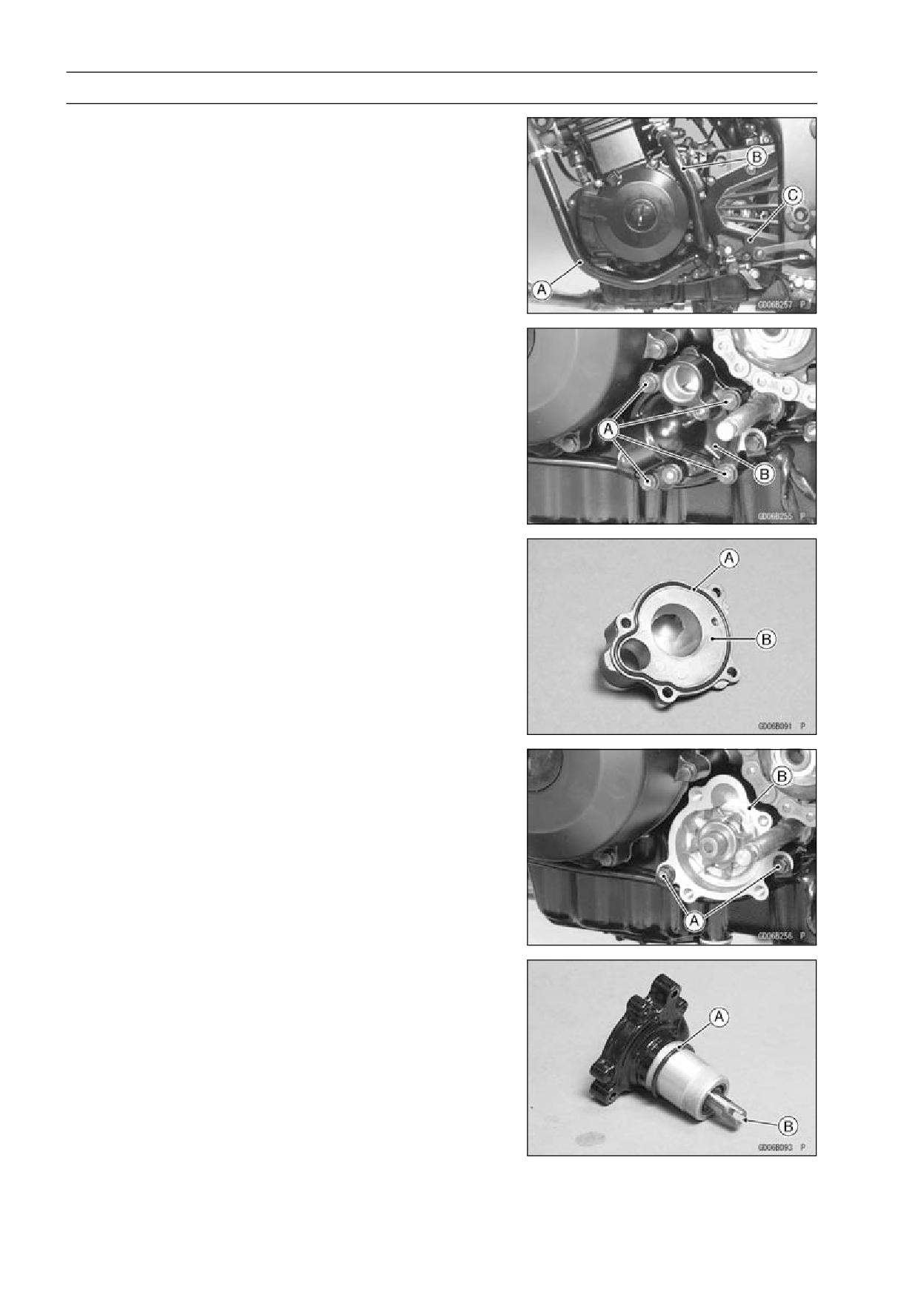
• Remove:
Left Lower Fairing (see Lower Fairing Removal in the
Frame chapter)
Coolant Pipes [A], [B]
Engine Sprocket Cover [C] (see Engine Sprocket Re-
moval in the Final chapter)
• Remove the water pump mounting bolts [A] and water
pump cover [B].
Pump Cover Installation
• Fit the O-ring [A] into the groove of the pump cover [B].
• Install the removed parts
Torque - Water Hose Clamp Screws: 3.0 N·m (0.31 kgf·m,
27 in·lb)
Water Pump Removal
• Remove:
Pump Cover (see Pump Cover Removal)
• Remove the water pump mounting bolts [A], and remove
the water pump [B].
Water Pump Installation
• Check the O-ring [A] visually whether or not there is a
damage on it.
• Grease the O-ring.
• Install the water pump aligning the slit [B] of water pump
shaft with the oil pump shaft.
COOLING SYSTEM 4-11
Water Pump
Pump Impeller Inspection
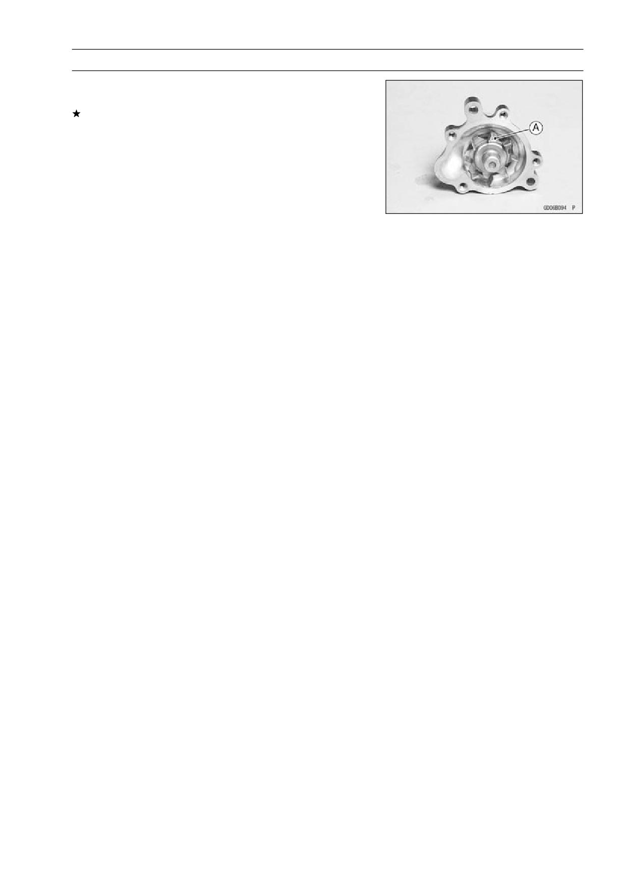
• Visually check the impeller [A].
If the surface is corroded or if the blades are damaged,
replace the water pump unit.
4-12 COOLING SYSTEM
Radiator, Radiator Fan
Radiator and Radiator Fan Removal
WARNING
A spinning radiator fan can cause serious injury.
The radiator fan is connected directly to the battery
and may start even if the ignition switch is off. Do
not touch the radiator fan until it has been discon-
nected from the battery.
• Remove the lower fairings (see Lower Fairing Removal in
the Frame chapter).
• Drain the coolant (see Coolant Change in the Periodic
Maintenance chapter).
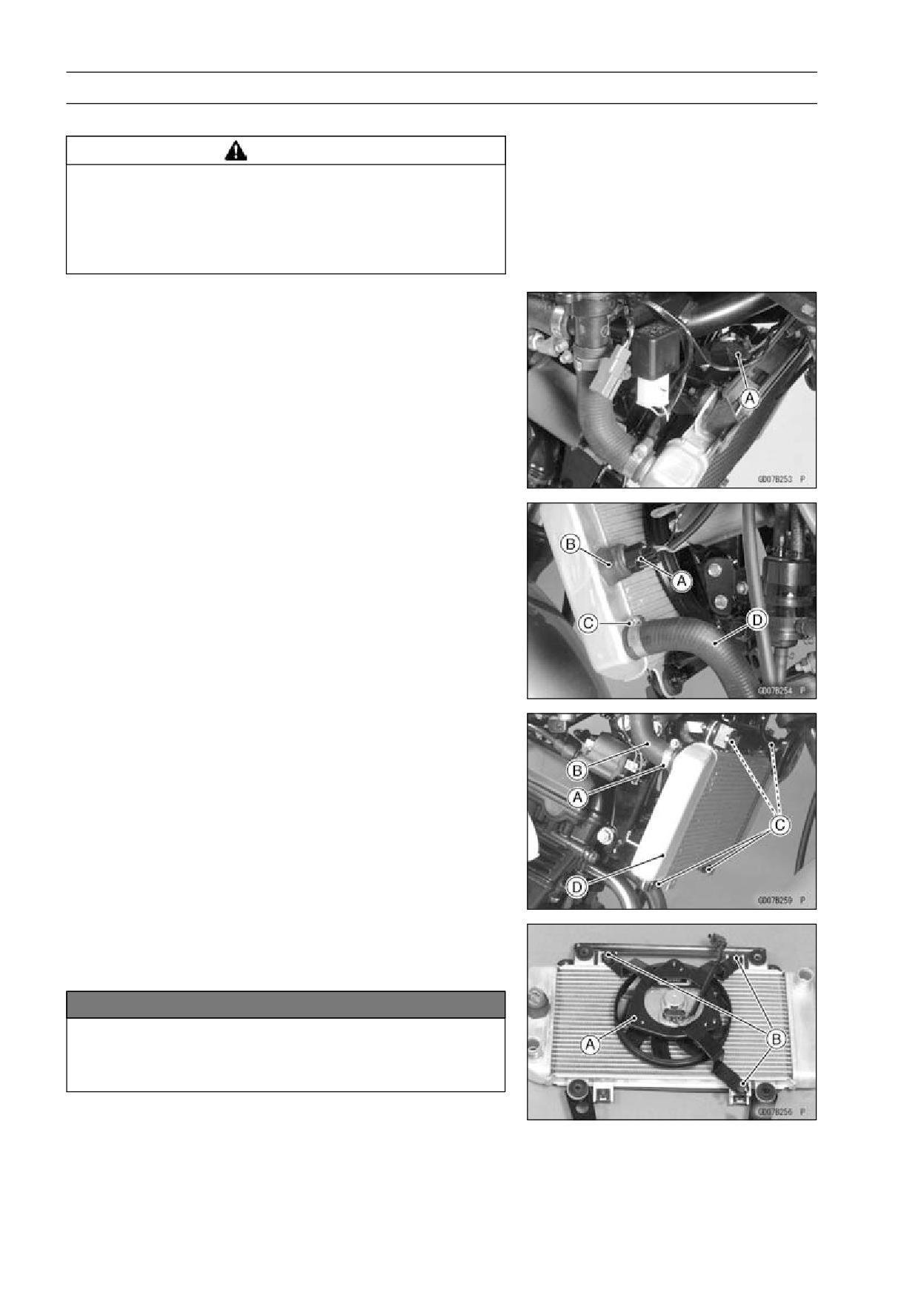
• Disconnect the fan motor lead connector [A] before re-
moval of the radiator or radiator fan.
• Disconnect the fan switch lead connector [A].
Fan Switch [B]
• Loosen the hose clamp [C] and pull off the water hose [D].
• Loosen the hose clamp [A] and pull off the water hose [B].
• Remove the radiator bolts [C] and take the radiator [D] off
the frame.
• Separate the filler and water hose from the radiator.
• Separate the radiator fan [A] from the radiator.
Radiator Fan Screws [B]
NOTICE
Do not touch the radiator core. This could damage
the radiator fins, resulting in loss of cooling effi-
ciency.
COOLING SYSTEM 4-13
Radiator, Radiator Fan
Radiator Inspection
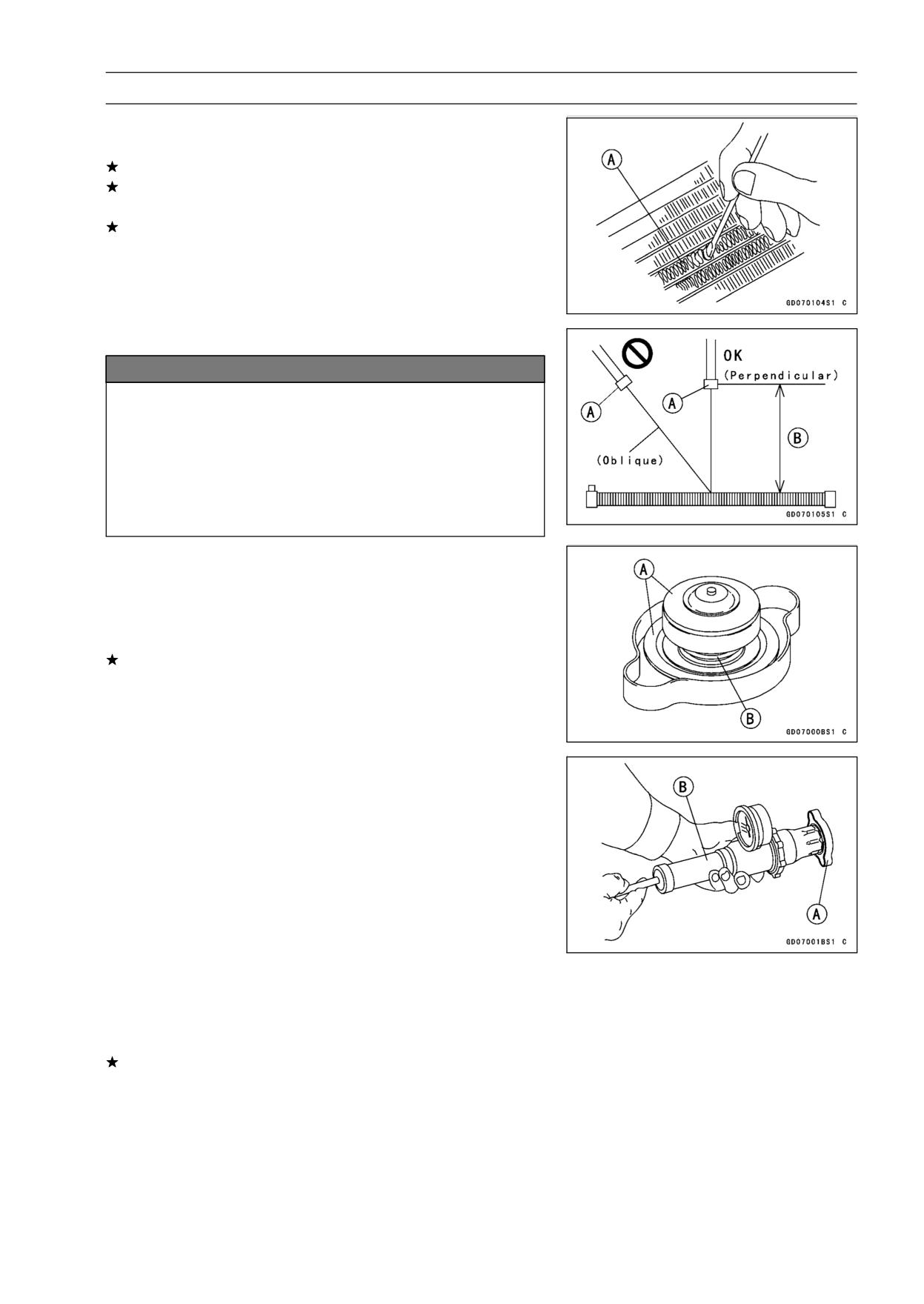
• Check the radiator core.
If there are obstructions to air flow, remove them.
If the corrugated fins [A] are deformed, carefully
straighten them.
If the air passages of the radiator core are blocked more
than 20% by unremovable obstructions or irreparably de-
formed fins, replace the radiator with a new one.
Radiator Cleaning
NOTICE
When cleaning the radiator with steam cleaner, be
careful of the following to prevent radiator damage.
Keep the steam gun [A] away more than 0.5 m (1.6
ft) [B] from the radiator core.
Hold the steam gun perpendicular to the core sur-
face.
Run the steam gun following the core fin direction.
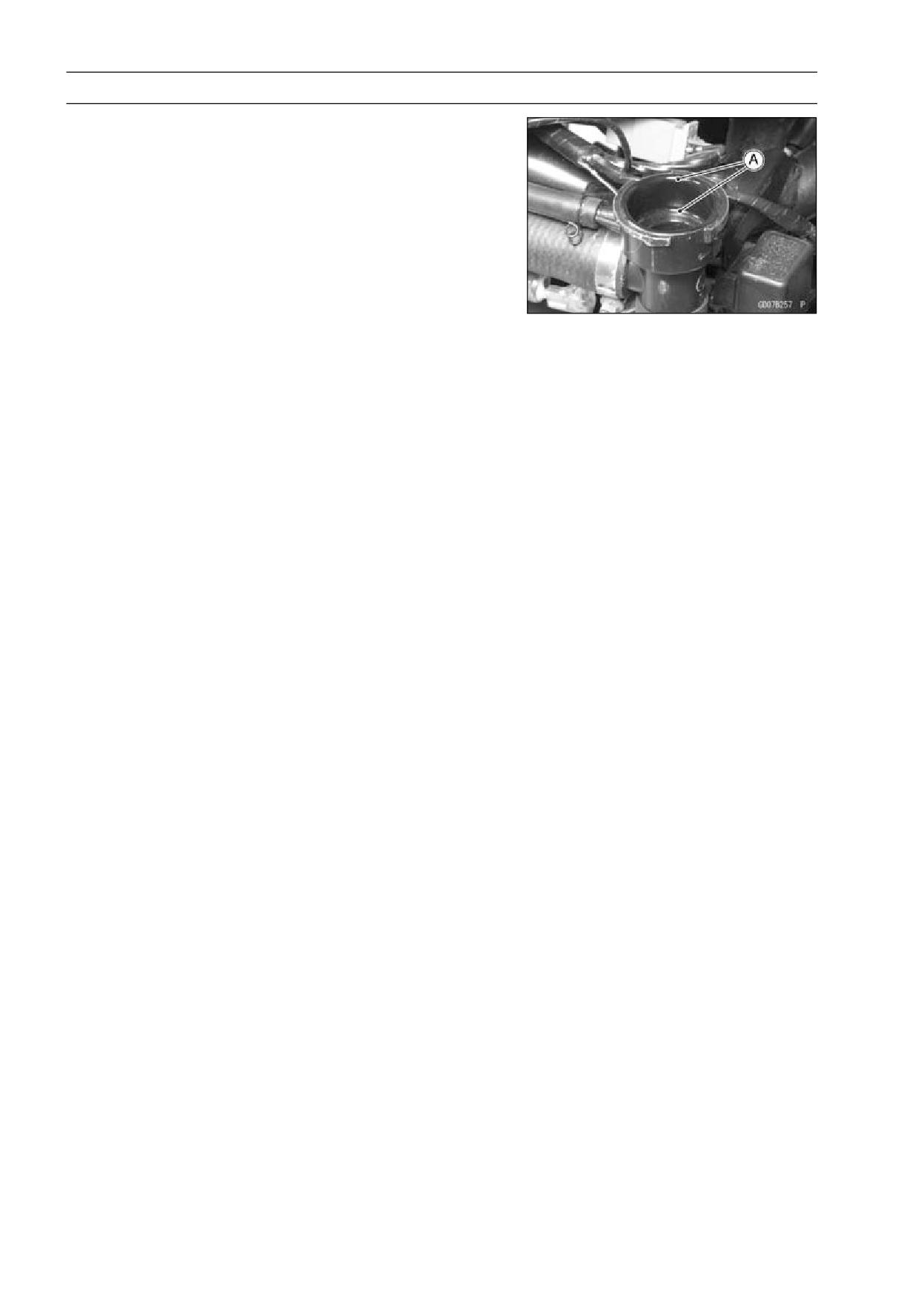
Radiator Cap Inspection
• Remove the right lower fairing (see Lower Fairing Re-
moval in the Frame chapter).
• Check the condition of the top and bottom valve seals [A]
and valve spring [B].
If any one of them shows visible damage, replace the cap
with a new one.
• Install the cap [A] on a cooling system pressure tester [B].
NOTE
○Wet the cap sealing surfaces with water or coolant to
prevent pressure leaks.
• Watching the pressure gauge, pump the pressure tester
to build up the pressure until the relief valve opens: the
gauge hand flicks downward. Stop pumping and measure
leak time at once. The relief valve must open within the
specified range in the table below and the gauge hand
must remain within the same range at least 6 seconds.
Radiator Cap Relief Pressure
Standard:
93 ∼ 123 kPa (0.95 ∼ 1.25 kgf/cm², 13 ∼ 18
psi)
If the cap cannot hold the specified pressure, or if it holds
too much pressure, replace it with a new one.
4-14 COOLING SYSTEM
Radiator, Radiator Fan
Radiator Filler Neck Inspection
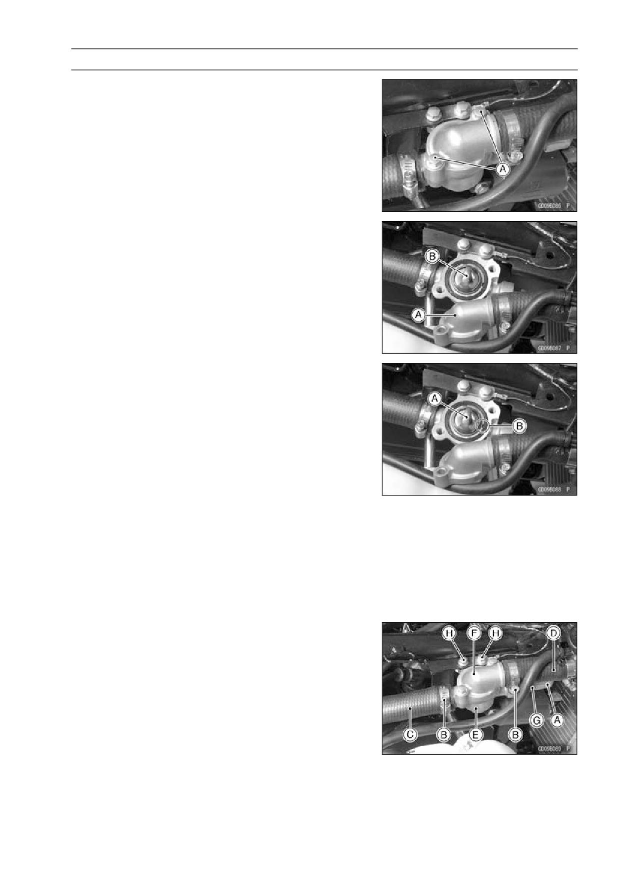
• Check the radiator filler neck for signs of damage.
• Check the condition of the top and bottom sealing seats
[A] in the filler neck. They must be smooth and clean for
the radiator cap to function properly.
COOLING SYSTEM 4-15
Thermostat
Thermostat Removal
• Drain the coolant (see Coolant Change in the Periodic
Maintenance chapter).
• Remove:
Front Seat (see Front Seat Removal in the Frame chap-
ter)
Fuel Tank (see Fuel Tank Removal in the Fuel System
chapter)
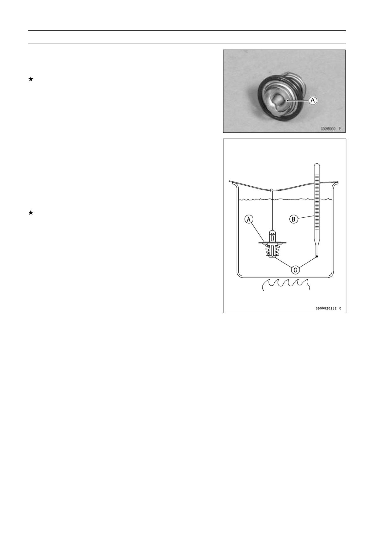
Thermostat Cover Bolts [A]
• Move the thermostat cover [A] outwards and remove the
thermostat [B].
Thermostat Installation
• Install the removed part in reverse of removal.
• Fit the thermostat [A] in the housing so that the air bleeder
hole [B] faces as shown.
• Fill the radiator with coolant.
Thermostat Housing Removal
• Drain the Coolant (see Coolant Change in the Periodic
Maintenance chapter).
• Remove:
Front Seat (see Front Seat Removal in the Frame chap-
ter)
Fuel Tank (see Fuel Tank Removal in the Fuel System
chapter)
• Disconnect the water temperature switch lead connector
[A].
• Loosen the water hose clamps [B] and slide the hoses
[C], [D] back and forth from the thermostat housing [E]
and cover [F].
Water Temperature Switch [G]
• Remove the thermostat housing mounting bolts [H] and
pull the housing out of the frame.
• Remove the thermostat cover and pull out the thermostat
if necessary.
Thermostat Housing Installation Note
• Be sure to install the ground lead on the thermostat hous-
ing mounting bolt.
4-16 COOLING SYSTEM
Thermostat
Thermostat Inspection
• Remove the thermostat, and visually inspect the thermo-
stat valve [A] at room temperature.
If the valve is open, replace the thermostat with a new
one.
• To check valve opening temperature, suspend the ther-
mostat [A] in a container of water and raise the tempera-
ture of the water.
○The thermostat must be completely submerged and must
not touch the container sides or bottom. Suspend an ac-
curate thermometer [B] in the water so that the heat sen-
sitive portions [C] are located in almost the same depth.
It must not touch the container, either.
If the measurement is out of the specified range, replace
the thermostat with a new one.
Thermostat Valve Opening Temperature
63.5 ∼ 66.5°C (146 ∼ 152°F)
COOLING SYSTEM 4-17
Hoses and Pipes
Hose Installation
• Install the hoses and pipes, being careful to follow bend-
ing direction. Avoid sharp bending, kinking, flattening or
twisting.
• Install the clamp [A] as near as possible to the hose end
to clear the raised rib of the fitting. This will prevent the
hoses from working loose.
○The clamp screws should be positioned correctly to pre-
vent the clamps from contacting anything.
Torque - Water Hose Clamp Screws: 3.0 N·m (0.31 kgf·m,
27 in·lb)
Hose Inspection
• Refer to Radiator Hose and Connection Inspection in the
Periodic Maintenance chapter (see Radiator Hose and
Connection Inspection in the Periodic Maintenance chap-
ter).
4-18 COOLING SYSTEM
Radiator Fan Switch, Water Temperature Switch
Radiator Fan Switch, Water Temperature Switch
Removal
NOTICE
The fan switch or the water temperature switch
should never be allowed to fall on a hard surface.
Such a shock to their parts can damage them.
• Drain the coolant (see Coolant Change in the Periodic
Maintenance chapter).
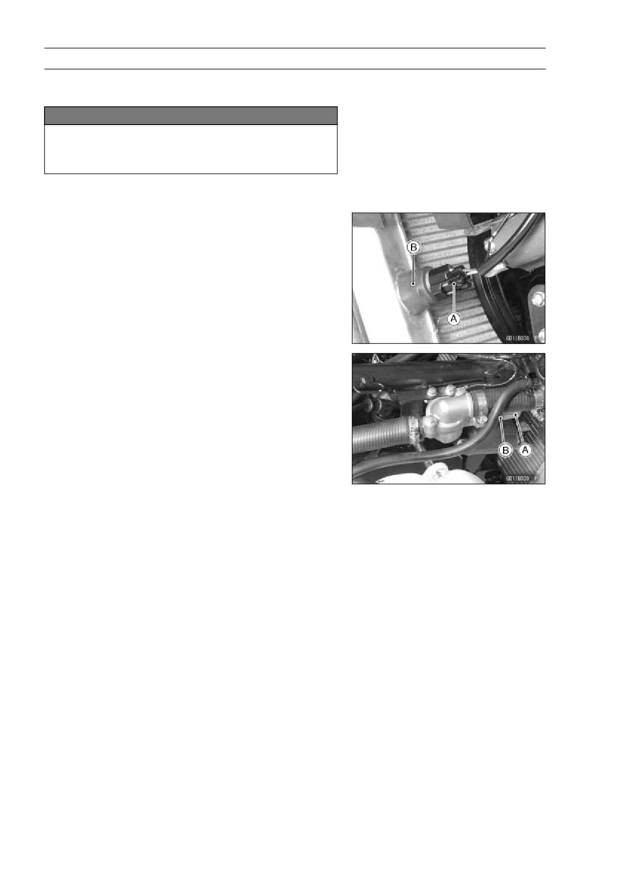
• Remove:
Radiator Fan Switch Lead Connector [A]
Radiator Fan Switch [B]
Front Seat (see Front Seat Removal in the Frame chap-
ter)
Fuel Tank (see Fuel Tank Removal in the Fuel System
chapter)
Water Temperature Switch Lead Connector [A]
Water Temperature Switch [B]
Radiator Fan Switch, Water Temperature Switch
Installation
• Apply liquid gasket to the threads of the water tempera-
ture switch.
Sealant - Liquid Gasket, TB1211: 56019-120
• Tighten the fan switch and water temperature sensor.
Torque - Radiator Fan Switch: 23.5 N·m (2.4 kgf·m, 17 ft·lb)
Water Temperature Switch: 7.5 N·m (0.76 kgf·m,
66 in·lb)
• Fill the coolant and bleed the air from cooling system (see
Coolant Change in the Periodic Maintenance chapter).
Radiator Fan Switch, Water Temperature Switch
Inspection
• Refer to Water Temperature Switch Inspection in the Elec-
trical System chapter (see Water Temperature Switch In-
spection in the Electrical System chapter).
ENGINE TOP END 5-1
Engine Top End
Table of Contents
Exploded View
5-2
Cylinder Head Removal
5-23
Exhaust System
5-6
Cylinder Head Installation
5-23
Specifications
5-8
Cylinder Head Warp Inspection ...
5-24
Special Tools and Sealant
5-10
Cylinder Head Cleaning
5-25
Clean Air System
5-12
Valves
5-26
Vacuum Switch Valve Removal ...
5-12
Valve Clearance Inspection
5-26
Vacuum Switch Valve Installation
5-12
Valve Clearance Adjustment
5-26
Vacuum Switch Valve Operation
Valve Removal
5-26
5
Test
5-12
Valve Installation
5-26
Vacuum Switch Valve Unit Test
5-12
Valve Guide Removal
5-26
Air Suction Valve Removal
5-13
Valve Guide Installation
5-26
Air Suction Valve Installation
5-13
Valve-to-Guide Clearance
Air Suction Valve Inspection
5-13
Measurement (Wobble
Clean Air System Hose
Method)
5-27
Inspection
5-14
Valve Seat Inspection
5-28
Cylinder Head Cover
5-15
Valve Seat Repair
5-28
Cylinder Head Cover Removal
5-15
Cylinder, Pistons
5-33
Cylinder Head Cover Installation .
5-15
Cylinder Removal
5-33
Camshaft Chain Tensioner
5-16
Cylinder Installation
5-33
Camshaft Chain Tensioner
Piston Removal
5-34
Removal
5-16
Piston Installation
5-34
Camshaft Chain Tensioner
Cylinder Wear Inspection
5-35
Installation
5-16
Piston Wear Inspection
5-35
Camshaft, Camshaft Chain
5-18
Piston Ring, Piston Ring Groove
Camshaft Removal
5-18
Wear Inspection
5-36
Camshaft Installation
5-18
Piston Ring Groove Width
Camshaft and Sprocket
Inspection
5-36
Assembly
5-20
Piston Ring Thickness Inspection
5-36
Camshaft and Camshaft Cap
Piston Ring End Gap Inspection..
5-37
Wear Inspection
5-20
Boring, Honing
5-37
Camshaft Runout Inspection
5-21
Carburetor Holder
5-38
Cam Wear Inspection
5-21
Carburetor Holder Installation
5-38
Camshaft Chain Guide Wear
Muffler
5-39
Inspection
5-21
Muffler Removal
5-39
Cylinder Head
5-22
Muffler Installation
5-39
Cylinder Compression
Exhaust System Inspection
5-40
Measurement
5-22
5-2 ENGINE TOP END
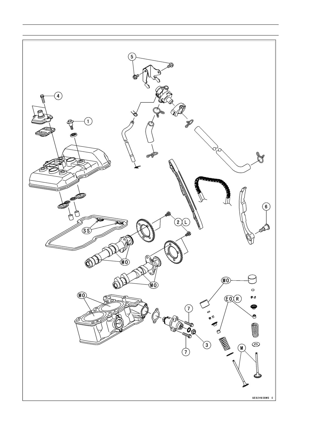
Exploded View
ENGINE TOP END 5-3
Exploded View
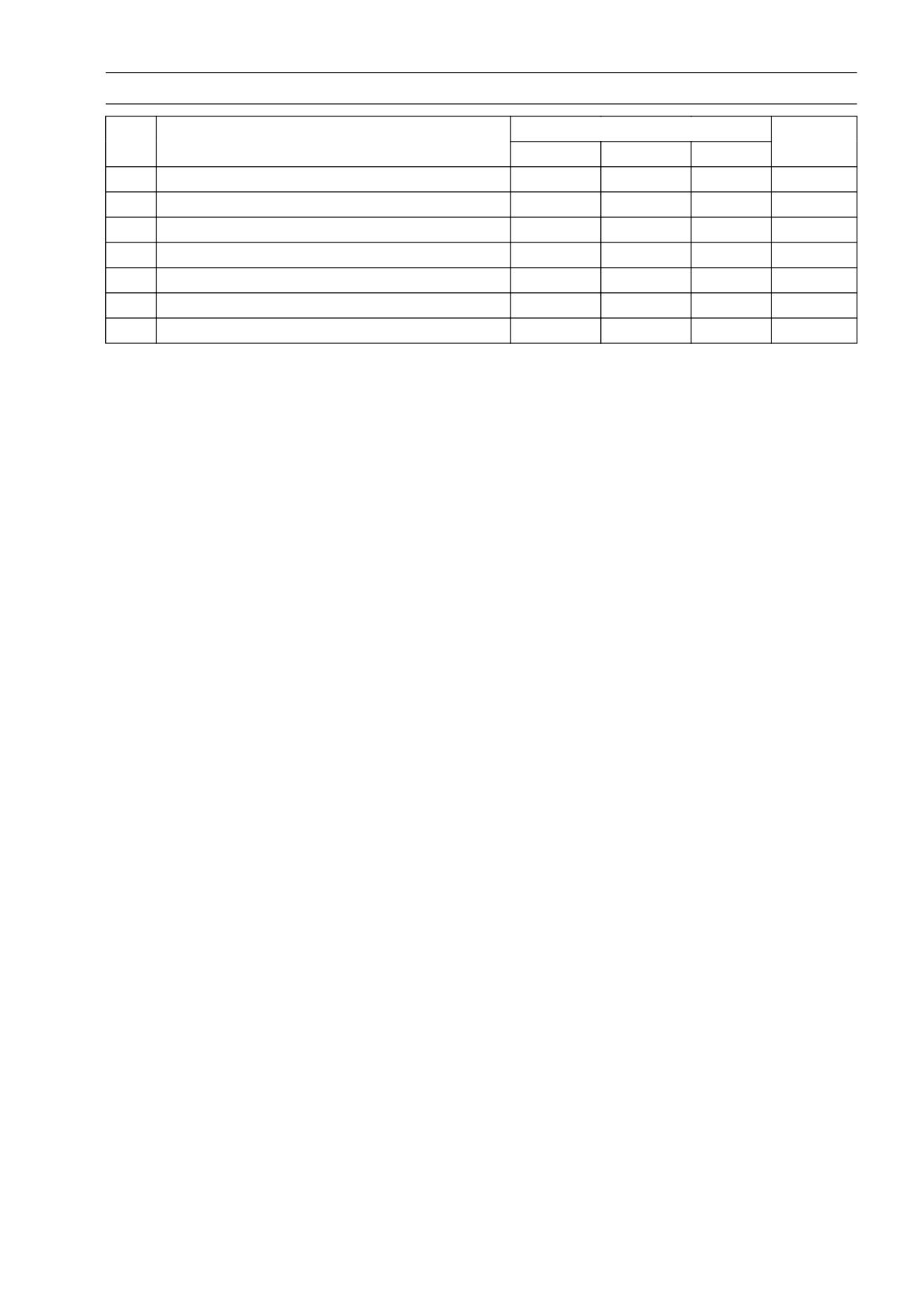
Torque
No.
Fastener
Remarks
N·m
kgf·m
ft·lb
1
Cylinder Head Cover Bolts
9.8
1.0
87 in·lb
2
Camshaft Sprocket Bolts
15
1.5
11
L
3
Chain Tensioner Cap Bolt
5.0
0.5
44 in·lb
4
Air Suction Cover Bolts
9.8
1.0
87 in·lb
5
Vacuum Switch Valve Bracket Bolts
9.8
1.0
87 in·lb
6
Rear Camshaft Chain Guide Bolt-Lower
17
1.7
13
7
Chain Tensioner Mounting Bolts
9.8
1.0
87 in·lb
EO: Apply engine oil.
L: Apply a non-permanent locking agent.
M: Apply molybdenum disulfide grease.
MO: Apply molybdenum disulfide oil solution (mixture of the engine oil and molybdenum disufide
grease in a weight ratio 10 : 1).
R: Replacement Parts
SS: Apply silicon sealant.
5-4 ENGINE TOP END
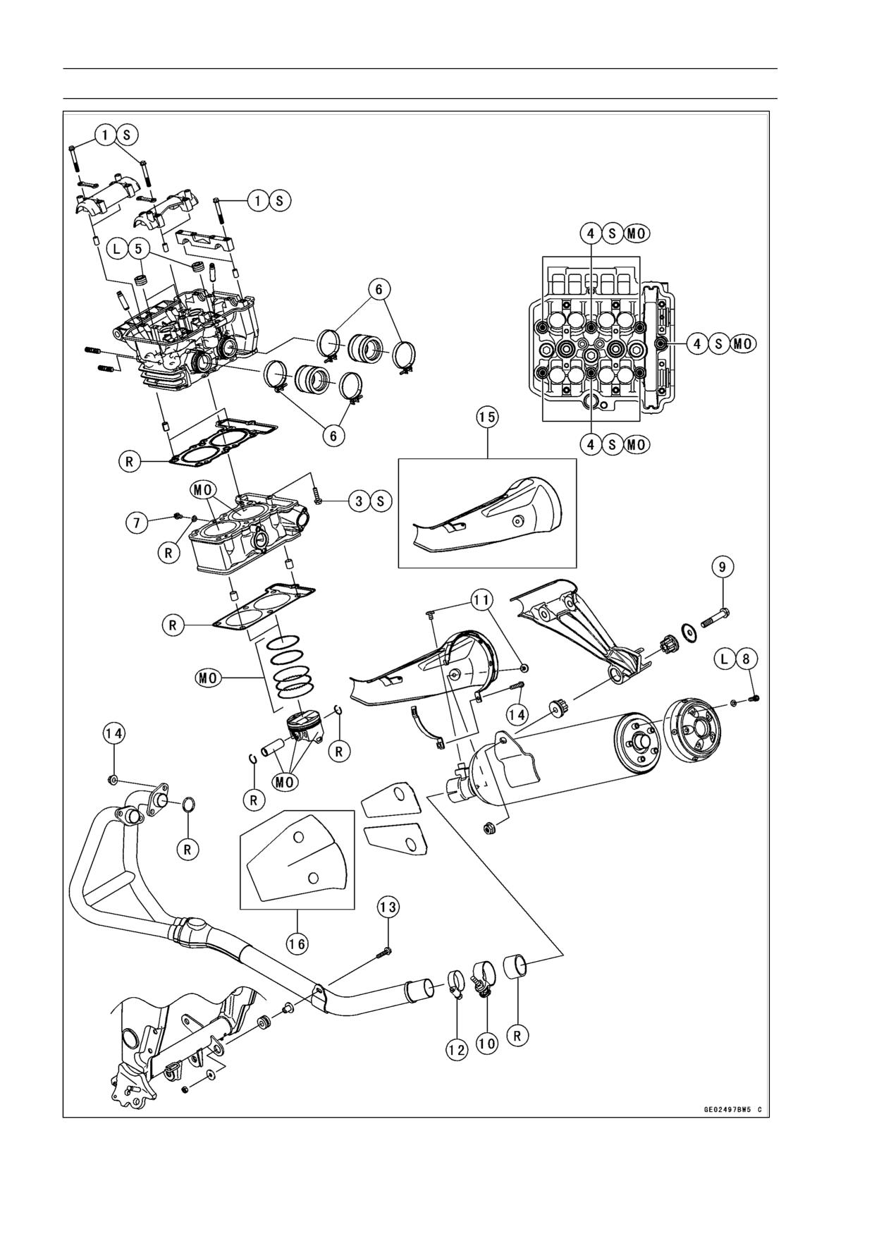
Exploded View
ENGINE TOP END 5-5
Exploded View
Torque
No.
Fastener
Remarks
N·m
kgf·m
ft·lb
1
Camshaft Cap Bolts
12
1.2
106 in·lb
S
2
Cylinder Head Bolt (M6)
12
1.2
106 in·lb
S
3
Cylinder Head Bolts (M8)
31.4
3.2
23
MO, S
4
Water Passage Plugs
20
2.0
15
L
5
Carburetor Holder Clamp Screws
2.0
0.2
18 in·lb
6
Water Drain Bolt
5.9
0.6
52 in·lb
7
Muffler Body Rear Cover Bolts
9.8
1.0
87 in·lb
L
8
Muffler Body Mounting Bolt
30
3.1
22
9
Muffler Body Clamp Bolt
17
1.7
13
10
Muffler Cover Bolts
9.8
1.0
87 in·lb
11
Muffler Cover Clamp Screw
6.9
0.70
61 in·lb
12
Exhaust Pipe Mounting Bolt
9.8
1.0
87 in·lb
13
Exhaust Pipe Holder Nuts
12
1.2
104 in·lb
14
Exhaust Pipe Chamber Clamp Screw
9.8
1.0
87 in·lb
15. EX250J8
16. EX250J8 ∼ JA
L: Apply a non-permanent locking agent.
MO: Apply molybdenum disulfide oil solution (mixture of the engine oil and molybdenum disufide
grease in a weight ratio 10 : 1).
S: Follow the specific tightening sequence.
5-6 ENGINE TOP END
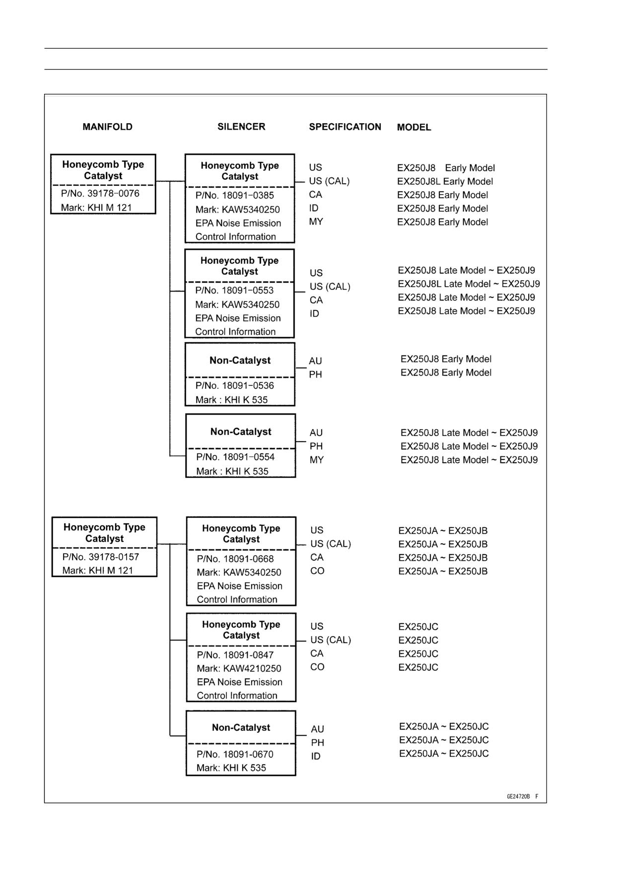
Exhaust System
Exhaust System
ENGINE TOP END 5-7
Exhaust System
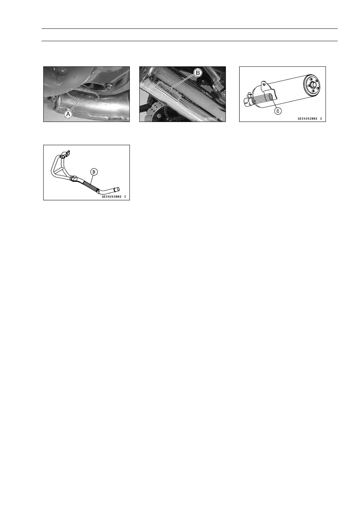
Manifold Mark Position [A]
Silencer Mark Position [B]
Honeycomb Type Catalyst
Position [C] of Silencer
Honeycomb Type Catalyst
Position [D] of Manifold
5-8 ENGINE TOP END
Specifications
Item
Standard
Service Limit
Clean Air System
Vacuum Switch Valve
Open → Close
Closing Pressure
41.3 ∼ 49.3 kPa (310 ∼ 370 mmHg)
- - -
Camshafts, Camshaft Chain,
Rocker Arms
Cam Height:
Exhaust
32.843 ∼ 32.957 mm (1.2930 ∼ 1.2975 in.)
32.74 mm (1.289 in.)
Inlet
33.843 ∼ 33.957 mm (1.3324 ∼ 1.3369 in.)
33.74 mm (1.328 in.)
Camshaft Journal, Camshaft
0.028 ∼ 0.071 mm (0.0011 ∼ 0.0028 in.)
0.16 mm (0.0063 in.)
Cap Clearance
Camshaft Journal Diameter
23.950 ∼ 23.972 mm (0.9429 ∼ 0.9438 in.)
23.92 mm (0.942 in.)
Camshaft Bearing Inside
24.000 ∼ 24.021 mm (0.9449 ∼ 0.9457 in.)
24.08 mm (0.948 in.)
Diameter
Camshaft Runout
TIR 0.02 mm (0.0008 in.) or less
TIR 0.1 mm (0.004 in.)
Cylinder Head
Cylinder Compression
(Usable Range)
980 ∼ 1 500 kPa (10.0 ∼ 15.3 kgf/cm², 142
- - -
∼ 218 psi) @470 r/min (rpm)
Cylinder Head Warp
---
0.05 mm (0.002 in.)
Valves
Valve Clearance:
Inlet
0.15 ∼ 0.24 mm (0.0059 ∼ 0.0094 in.)
- - -
Exhaust
0.22 ∼ 0.29 mm (0.0087 ∼ 0.0114 in.)
- - -
Valve Head Thickness:
Inlet
0.50 mm (0.0197 in.)
0.3 mm (0.012 in.)
Exhaust
0.80 mm (0.0315 in.)
0.5 mm (0.020 in.)
Valve Stem Bend
TIR 0.01 mm (0.0004 in.) or less
TIR 0.05 mm (0.002 in.)
Valve Stem Diameter:
Inlet
4.475 ∼ 4.490 mm (0.1762 ∼ 0.1768 in.)
4.46 mm (0.176 in.)
Exhaust
4.455 ∼ 4.470 mm (0.1754 ∼ 0.1760 in.)
4.44 mm (0.175 in.)
Valve Guide Inside Diameter
4.500 ∼ 4.512 mm (0.1772 ∼ 0.1776 in.)
4.58 mm (0.180 in.)
Valve/valve Guide Clearance
(Wobble Method):
Inlet
0.03 ∼ 0.09 mm (0.0012 ∼ 0.035 in.)
0.27 mm (0.011 in.)
Exhaust
0.08 ∼ 0.15 mm (0.0031 ∼ 0.0059 in.)
0.33 mm (0.013 in.)
Valve Seating Surface:
Outside Diameter:
Inlet
21.9 ∼ 22.1 mm (0.8622 ∼ 0.8701 in.)
- - -
Exhaust
19.3 ∼ 19.5 mm (0.7598 ∼ 0.7677 in.)
- - -
Width
0.5 ∼ 1.0 mm (0.0197 ∼ 0.0394 in.)
- - -
Valve Spring Free Length:
Inlet
39.5 mm (1.555 in.)
38.0 mm (1.50 in.)
Exhaust
39.5 mm (1.555 in.)
38.0 mm (1.50 in.)
Valve Seat Cutting Angle
32°, 45°, 67.5°
- - -
ENGINE TOP END 5-9
Specifications
Item
Standard
Service Limit
Cylinder, Pistons
Cylinder Inside Diameter
62.000 ∼ 62.012 mm (2.4409 ∼ 2.4414 in.)
62.10 mm (2.44 in.)
Piston Diameter
61.942 ∼ 61.957 mm (2.4387 ∼ 2.4392 in.)
61.80 mm (2.43 in.)
Piston/Cylinder Clearance
0.043 ∼ 0.070 mm (0.0017 ∼ 0.0028 in.)
- - -
Oversize Pistons and Rings
+0.5 mm (0.020 in.)
- - -
Piston Ring/Groove
Clearance:
Top
0.03 ∼ 0.07 mm (0.0012 ∼ 0.0028 in.)
0.17 mm (0.0067 in.)
Second
0.02 ∼ 0.06 mm (0.0008 ∼ 0.0024 in.)
0.16 mm (0.0063 in.)
Piston Ring Groove Width:
Top
0.82 ∼ 0.84 mm (0.0323 ∼ 0.0331 in.)
0.92 mm (0.0362 in.)
Second
0.81 ∼ 0.83 mm (0.0319 ∼ 0.0327 in.)
0.91 mm (0.0358 in.)
Oil
1.51 ∼ 1.53 mm (0.0594 ∼ 0.0602 in.)
1.61 mm (0.0634 in.)
Piston Ring Thickness:
Top, Second
0.77 ∼ 0.79 mm (0.0303 ∼ 0.0311 in.)
0.7 mm (0.028 in.)
Piston Ring End Gap:
Top
0.15 ∼ 0.30 mm (0.0059 ∼ 0.0118 in.)
0.6 mm (0.024 in.)
Second
0.40 ∼ 0.55 mm (0.0157 ∼ 0.0217 in.)
0.9 mm (0.035 in.)
Oil
0.20 ∼ 0.80 mm (0.0079 ∼ 0.0315 in.)
1.1 mm (0.043 in.)

5-10 ENGINE TOP END
Special Tools and Sealant
Compression Gauge, 20 kgf/cm²:
Valve Seat Cutter Holder Bar:
57001-221
57001-1128
Valve Spring Compressor Assembly:
Valve Seat Cutter, 32° -
22:
57001-241
57001-1206
Piston Pin Puller Assembly:
Valve Seat Cutter, 67.5° -
22:
57001-910
57001-1207
Valve Seat Cutter, 45° -
24.5:
Valve Spring Compressor Adapter,
16:
57001-1113
57001-1305
Valve Seat Cutter, 32° -
25:
Compression Gauge Adapter, M10 × 1.0:
57001-1118
57001-1317

ENGINE TOP END 5-11
Special Tools and Sealant
Valve Seat Cutter Holder,
4.5:
Valve Guide Driver:
57001-1330
57001-1564
Valve Guide Arbor,
4.5:
Washer:
57001-1331
57001-1720
Valve Guide Reamer,
4.5:
Liquid Gasket, TB1216B:
57001-1333
92104-1064
Piston Base,
2.3:
57001-1336
5-12 ENGINE TOP END
Clean Air System
Vacuum Switch Valve Removal
• Remove:
Fuel Tank (see Fuel Tank Removal in the Fuel System
Chapter)
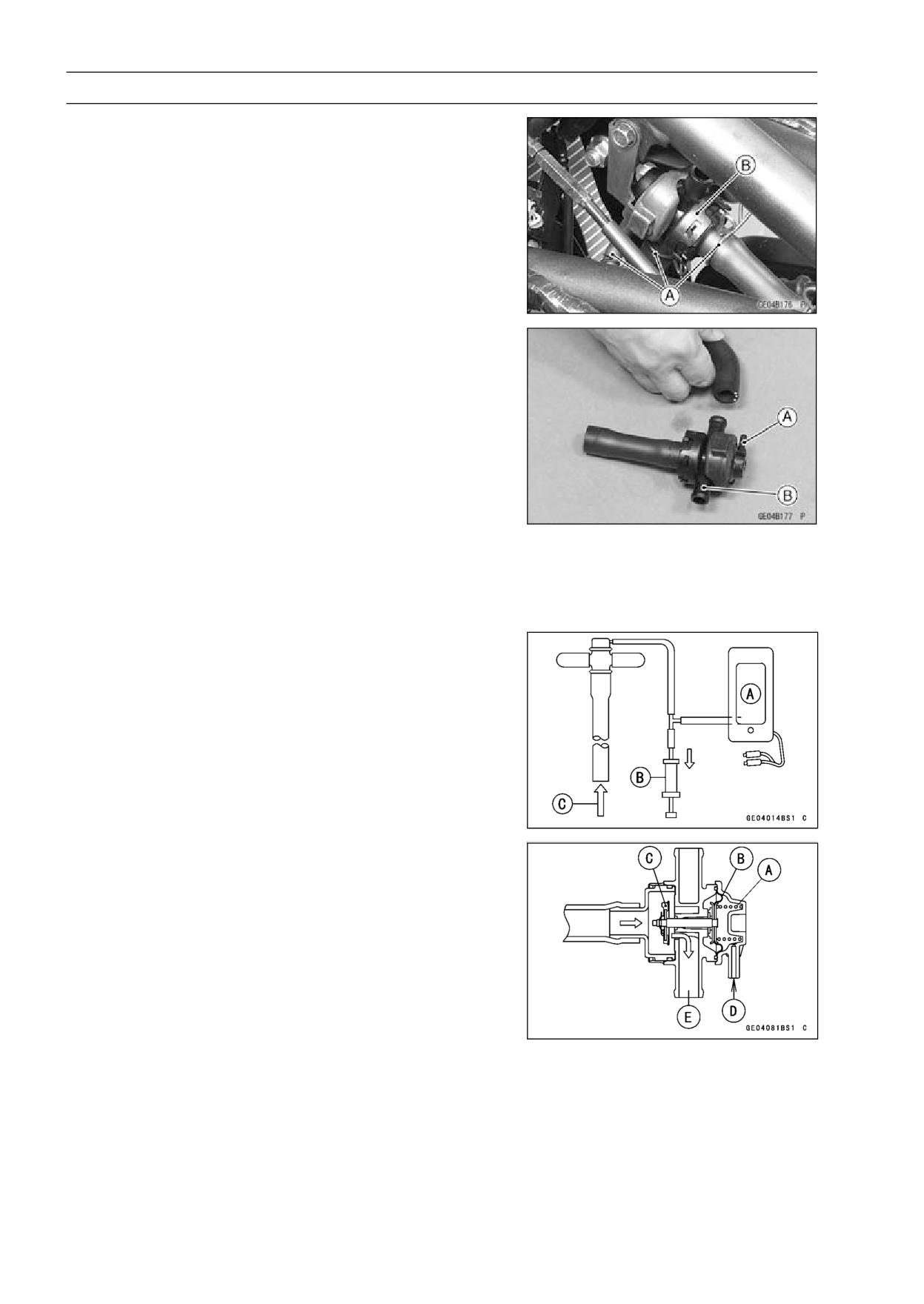
Vacuum Switch Valve Hose Ends [A]
Vacuum Switch Valve [B]
Vacuum Switch Valve Installation
• Install the vacuum switch valve so that the vacuum hose
fitting [A] faces downwards (see Cable, Wire, and Hose
Routing in the Appendix chapter).
NOTE
○This hose fitting [B] side is plugged.
Vacuum Switch Valve Operation Test
• Refer to Air Suction System Damage Inspection in the
Periodic Maintenance chapter (see Air Suction System
Damage Inspection in the Periodic Maintenance chapter).
Vacuum Switch Valve Unit Test
• Remove the fuel tank (see Fuel Tank Removal in the Fuel
System chapter).
○Do not remove the vacuum switch valve.
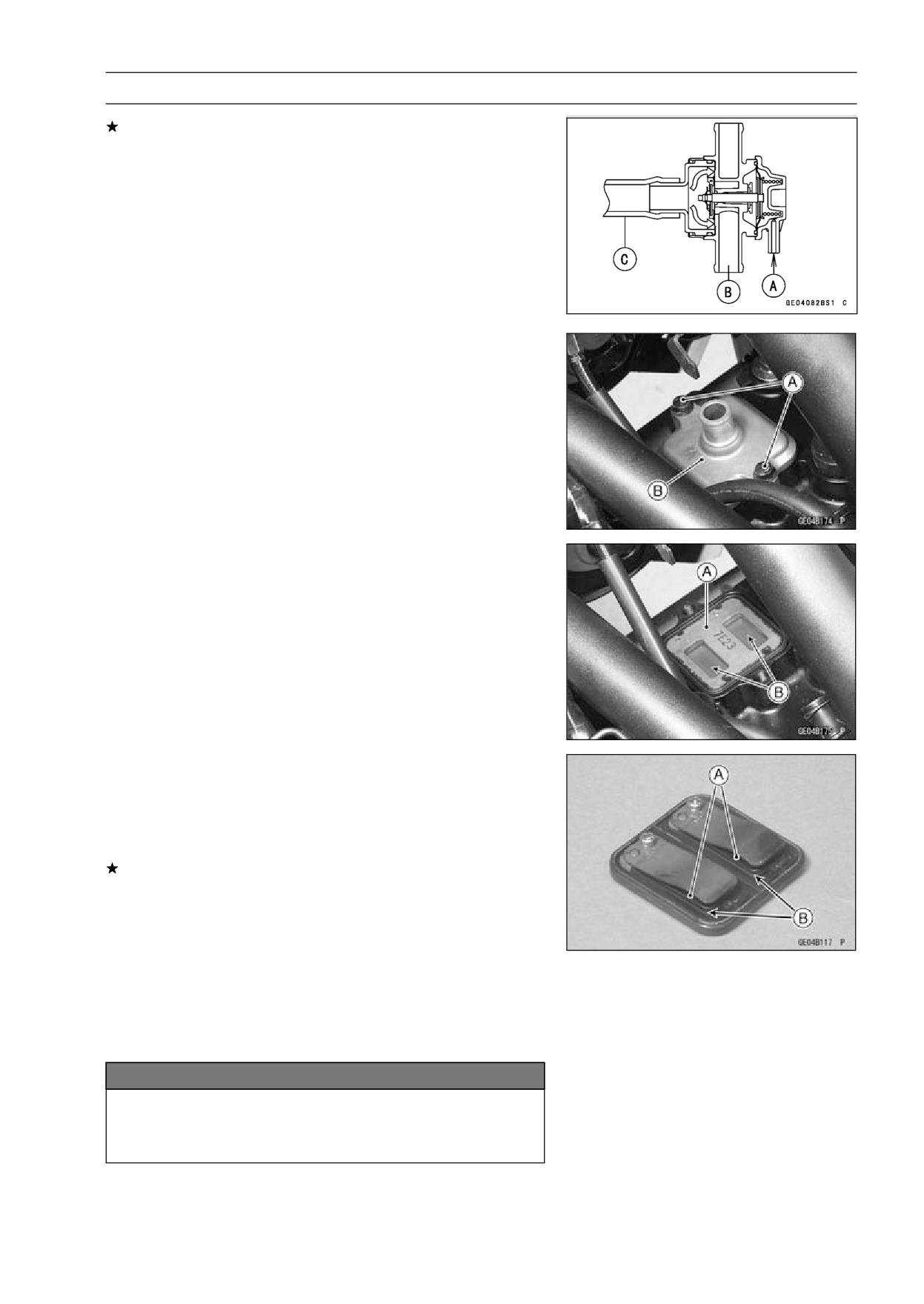
• Connect a vacuum gauge [A] and syringe [B] or the fork
oil level gauge to the vacuum hose as shown.
Special Tool - Fork Oil Level Gauge: 57001-1290
Air Flow [C]
• Gradually raise the vacuum (lower the pressure) applied
to the vacuum switch valve, and check the valve opera-
tion. When the vacuum is low, the vacuum switch valve
should permit air to flow. When the vacuum is raised to
valve closing pressure, the valve should stop air flow.
Spring [A]
Diaphragm [B]
Valve [C]
Low Vacuum [D]
Secondary Air Flow [E]
ENGINE TOP END 5-13
Clean Air System
If the vacuum switch valve does not operate as described,
replace it with a new one.
NOTE
○To check air flow through the vacuum switch valve, just
blow through the vacuum switch hose [C].
Vacuum Switch Valve Closing Pressure (Open → Close)
Standard:
41.3 ∼ 49.3 kPa (310 ∼ 370 mmHg)
High Vacuum [A]
Secondary air cannot flow [B]
Air Suction Valve Removal
• Remove:
Fuel Tank (see Fuel Tank Removal in the Fuel System
chapter)
Vacuum Switch Valve (see Vacuum Switch Valve Re-
moval)
• Unscrew the bolts [A] and remove the air suction valve
covers [B].
Air Suction Valve Installation
• Install the air suction valve [A] so that its reed opening
side [B] faces backwards.
Torque - Air Suction Valve Cover Bolts : 9.8 N·m (1.0 kgf·m,
87 in·lb)
Air Suction Valve Inspection
• Remove the air suction valve (see Air Suction Valve Re-
moval).
• Visually inspect the reeds for cracks, folds, warps, heat
damage or other damage.
If there is any doubt as to the condition of the reeds [A],
replace the air suction valve as an assembly.
• Check the reed contact areas [B] of the valve holder for
grooves, scratches, any signs of separation from the
holder or heat damage.
• If there is any doubt as to the condition of the reed contact
areas, replace the air suction valve as an assembly.
• If any carbon or other foreign particles have accumulated
between the reed and the reed contact area, wash the
valve assembly clean with a high-flash point solvent.
NOTICE
Do not scrape off the deposits with a scraper as this
could damage the rubber, requiring replacement of
the suction valve assembly.
5-14 ENGINE TOP END
Clean Air System
Clean Air System Hose Inspection
• Be certain that all the hoses are routed without being flat-
tened or kinked, and are connected correctly to the air
cleaner housing, carburetor assembly and cylinder head
cover (see Cable, Wire, and Hose Routing section in the
Appendix chapter).
If they are not, correct them. Replace them if they are
damaged.
ENGINE TOP END 5-15
Cylinder Head Cover
Cylinder Head Cover Removal
• Drain the Coolant (see Coolant Change in the Periodic
Maintenance chapter).
• Remove:
Spark Plug Caps
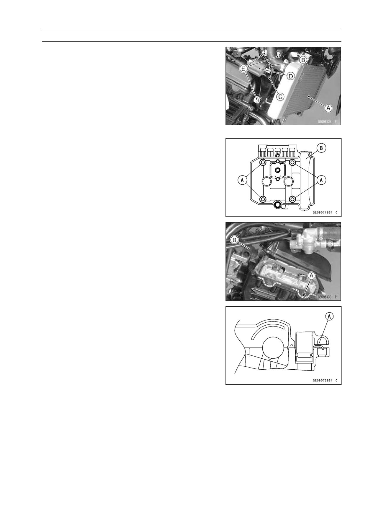
Radiator [A] (see Radiator and Radiator Fan Removal in
the Cooling System chapter)
• Disconnect the primary lead [B] and ground lead [C] con-
nectors of the #2(right) ignition coil [D].
• Remove the right engine bracket mounting bolts [E], and
remove the engine bracket with the right ignition coil.
• Disconnect the air suction valve hose.
• Remove the cylinder head cover bolts [A].
• Remove the cylinder head cover [B].
Cylinder Head Cover Installation
• Scrape off the old gasket [A] on the cylinder head mating
surface, and apply liquid gasket [A] on the mating surface.
Sealant - Liquid Gasket, TB1216B: 92104-1064
• Be sure the water pipe [B] is in place.
• Be sure the damper [A] on the water pipe is in position.
• Install the new cylinder head cover gasket and install the
cylinder head cover with the specified torque.
Torque - Cylinder Head Cover Bolts: 9.8 N·m (1.0 kgf·m, 87
in·lb)
• Install the removed parts.
5-16 ENGINE TOP END
Camshaft Chain Tensioner
Camshaft Chain Tensioner Removal
NOTICE
This is a non-return type camshaft chain tensioner.
The push rod does not return to its original position
once it moves out to take up camshaft chain slack.
Observe all the rules listed below:
When removing the tensioner, do not take out the
mounting bolts only halfway. Retightening the
mounting bolts from this position could damage
the tensioner and the camshaft chain. Once the
bolts are loosened, the tensioner must be removed
and reset as described in “Camshaft Chain Ten-
sioner Installation”.
Do not turn over the crankshaft while the tensioner
is removed. This could upset the camshaft chain
timing and damage the valves.
• Remove the right lower fairing (see Lower Fairing Re-
moval in the Frame chapter).
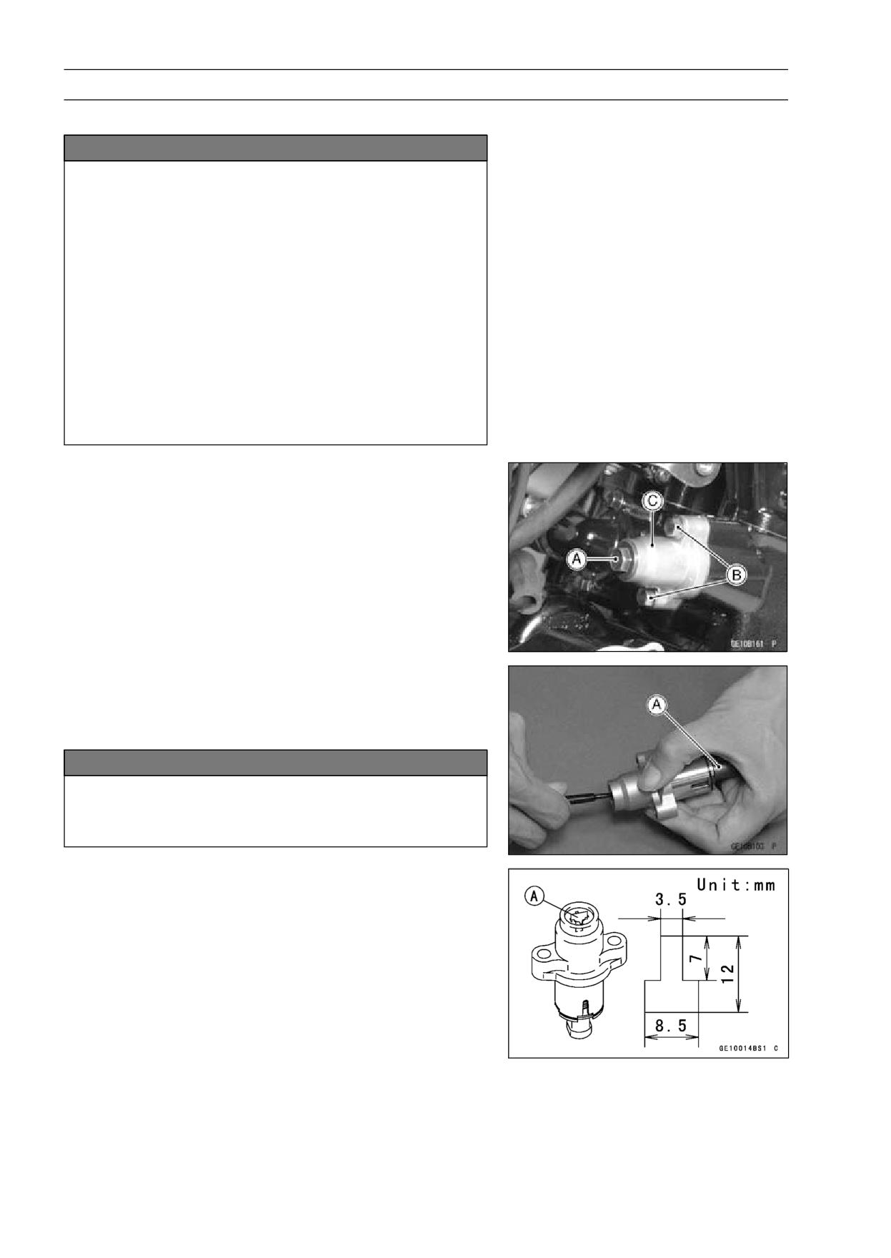
• Loosen the cap bolt [A]
• Remove the tensioner mounting bolts [B], and remove the
chain tensioner body [C].
Camshaft Chain Tensioner Installation
• Remove the tensioner cap bolt and O-ring.
• While compressing the push rod [A], turn it clockwise with
a suitable screwdriver until the rod stopped.
NOTICE
Do not turn the rod counterclockwise before in-
stalling the tensioner. This could detach the rod
and the tensioner cannot be reinstalled.
• While holding the rod in position with a suitable push rod
holder plate [A] install the tensioner on the cylinder block.
ENGINE TOP END 5-17
Camshaft Chain Tensioner
• Replace the chain tensioner gasket with a new one.
• Tighten:
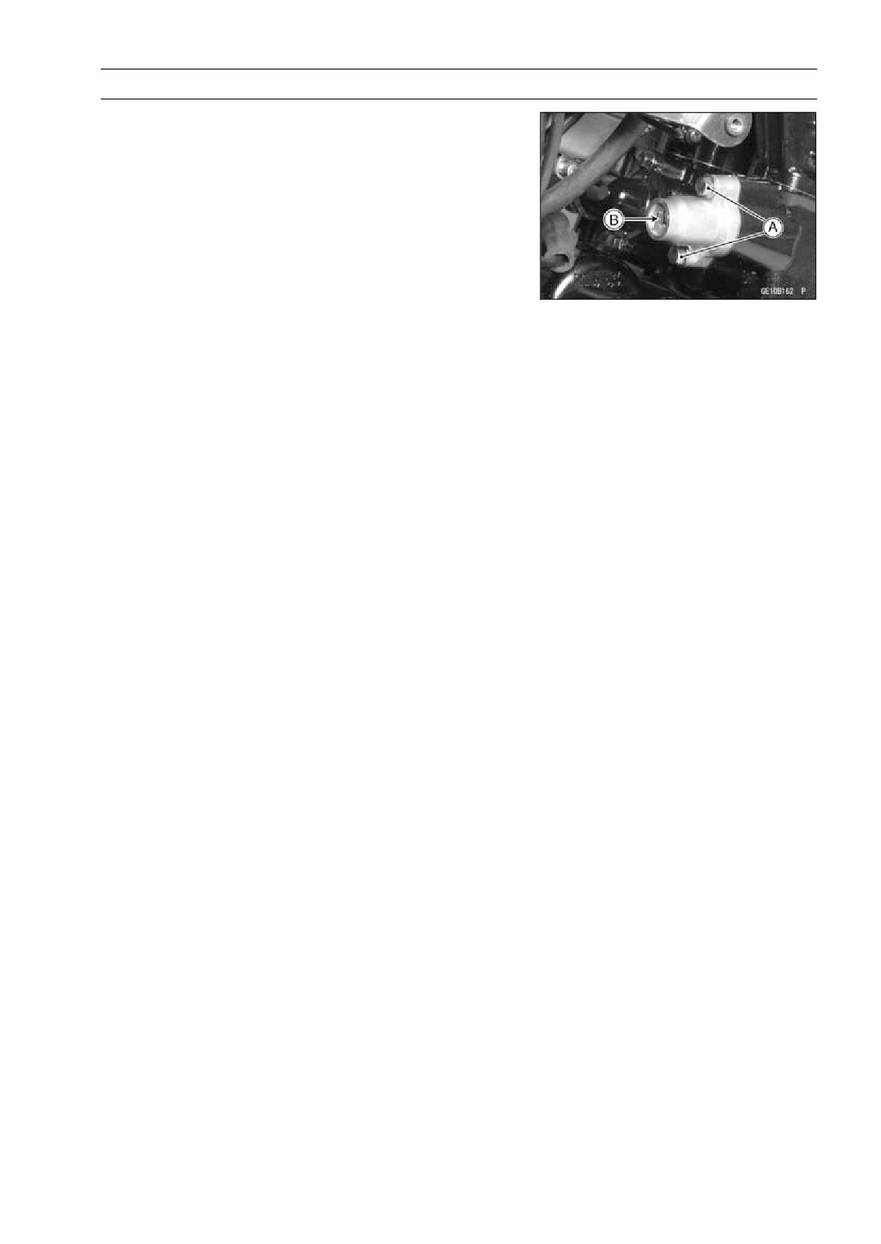
Torque - Chain Tensioner Mounting Bolts [A]: 9.8 N·m (1.0
kgf·m, 87 in·lb)
• Take out the holder plate [B].
• Install the O-ring and tighten the cap bolt.
Torque - Chain Tensioner Cap Bolt: 5.0 N·m (0.5 kgf·m, 44
in·lb)
5-18 ENGINE TOP END
Camshaft, Camshaft Chain
Camshaft Removal
• Remove the cylinder head cover (see Cylinder Head
Cover Removal).
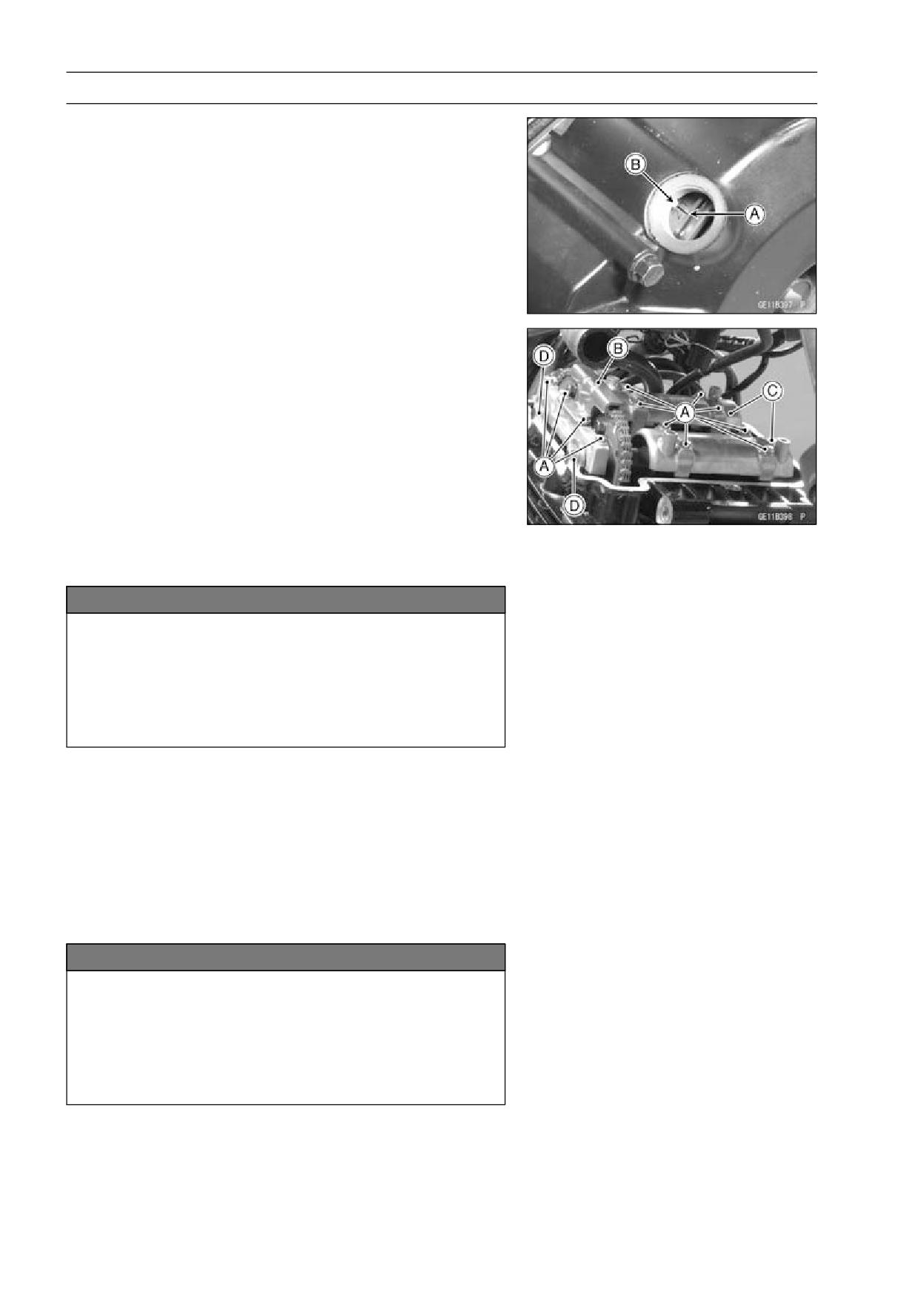
• Remove the inspection plugs on the alternator cover.
• Position the crankshaft at #2 piston TDC.
○Using a wrench on the crankshaft rotation bolts, turn the
crankshaft clockwise until the “2T” mark [A] on the alterna-
tor rotor is aligned with the projection [B] in the inspection
window on the alternator cover.
• Remove:
Camshaft Chain Tensioner (see Camshaft Chain Ten-
sioner Removal).
Camshaft Cap Bolts [A]
Plates
Camshaft Top Chain Guide [B]
Camshaft Caps [C]
Camshafts [D]
• Stuff a clean cloth into the camshaft chain tunnel to keep
any parts from dropping into the crankcase.
NOTICE
The crankshaft may be turned while the camshafts
are removed.
Always pull the chain taut while turning the crank-
shaft. This avoids kinking the chain on the lower
(crankshaft) sprocket. A kinked chain could dam-
age both the chain and the sprocket.
Camshaft Installation
• Apply molybdenum disulfide oil solution to the cam and
journal surfaces.
NOTE
○Be sure to operate from the engine left side.
• Position the crankshaft at #2 piston TDC (see Camshaft
Removal).
NOTICE
The crankshaft may be turned while the camshafts
are removed.
Always pull the chain taut while turning the crank-
shaft. This avoids kinking the chain on the lower
(crankshaft) sprocket. A kinked chain could dam-
age both the chain and the sprocket.
ENGINE TOP END 5-19
Camshaft, Camshaft Chain
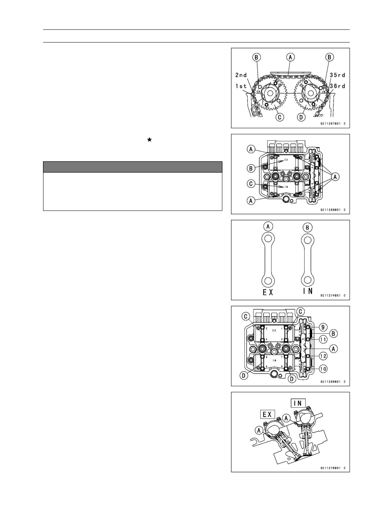
• Engage the camshaft chain [A] with the camshaft sprock-
ets.
○Pull the tension side (exhaust side) of the chain taut to
install the chain on the sprockets.
○Timing marks [B] align with the cylinder head upper sur-
face.
Exhaust Camshaft Sprocket [C]
Inlet Camshaft Sprocket [D]
○Count the camshaft chain link pins as shown to verify that
the sprocket are positioned correctly.
marks [A].
• Place the six dowel pins on the
• Install the camshaft caps as shown, noting the “EX” [B]
and “IN” [C] marks.
NOTICE
The camshaft caps are machined with the cylinder
head. So, if a cap is installed in a wrong location,
the camshaft may seize because of improper oil
clearance in the bearings.
• Put the plates on the bearing caps.
○The exhaust side plates [A] is longer the inlet side plates
[B].
• First tighten down the chain guide [A] and bearing caps
[B] evenly to seat the camshafts in place, then tighten all
bolts following the specified tightening sequence.
Torque - Camshaft Cap Bolts: 12 N·m (1.2 kgf·m, 106 in·lb)
Plates (EX) [C]
Plates (IN) [D]
• Install the camshaft chain tensioner (see Camshaft Chain
Tensioner Installation).
• Check the chain timing.
• Finally, inject [A] engine oil into 8 places on the cylinder
head, as shown.
5-20 ENGINE TOP END
Camshaft, Camshaft Chain
Camshaft and Sprocket Assembly
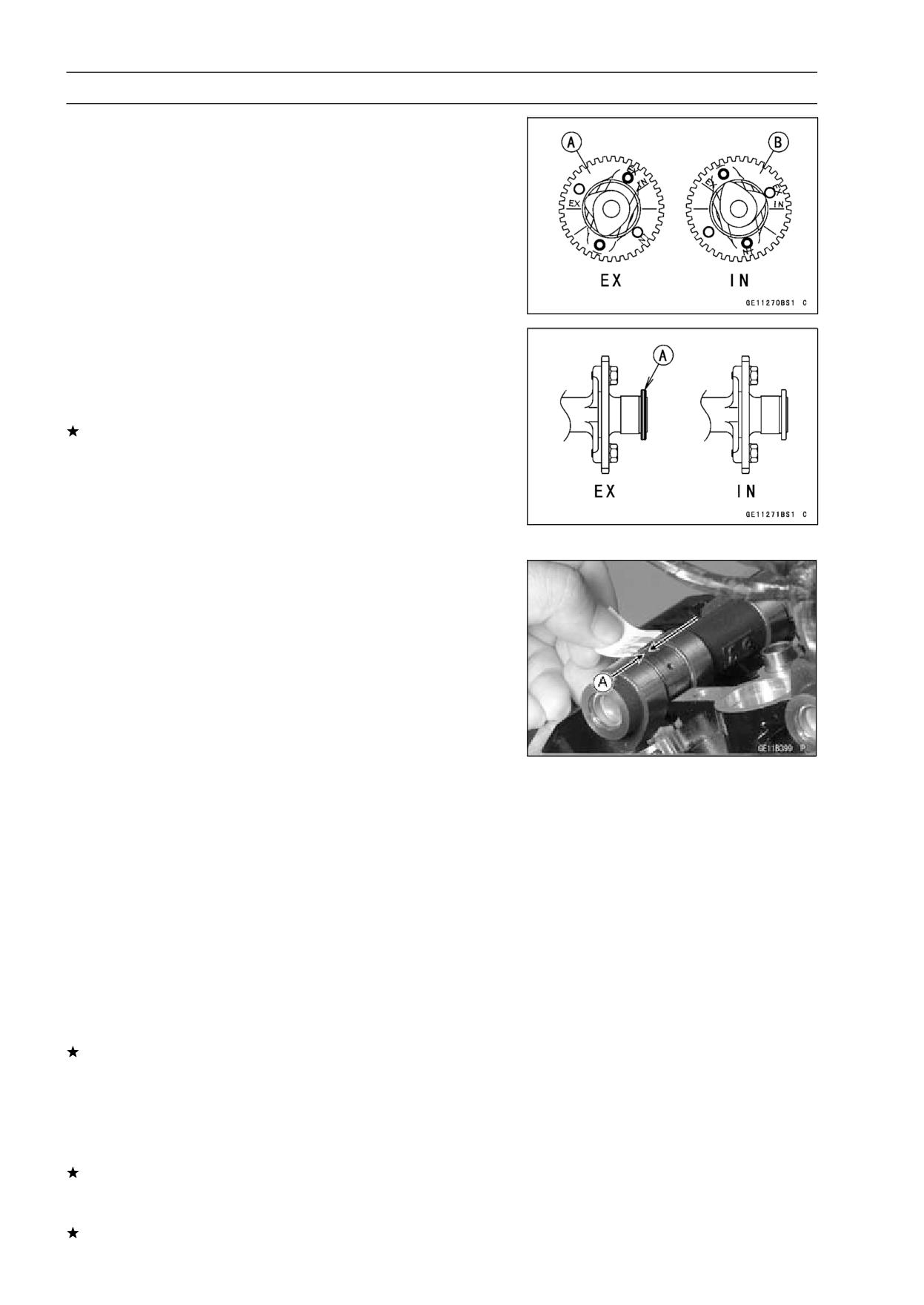
• Install the cam sprockets as shown in figure.
Exhaust Cam Sprocket [A]
Inlet Cam Sprocket [B]
• Apply a non-permanent locking agent to the camshaft
sprocket bolts and tighten them.
Torque - Camshaft Sprocket Bolts: 15 N·m (1.5 kgf·m, 11
ft·lb)
If a new camshaft is to be used, apply a thin coat of a
molybdenum disulfide grease to the cam surfaces.
NOTE
○The exhaust camshaft has a groove [A] and the inlet
camshaft has no groove. Be careful not to mix up these
shafts.
Camshaft and Camshaft Cap Wear Inspection
• Remove:
Camshaft Top Guide
Camshaft Caps
• Cut the strips of plastigauge to journal parallel to the
camshaft installed in the correct position.
• Measure each clearance between the camshaft journal
and the camshaft cap using the plastigauge (press gauge)
[A].
• Tighten:
Torque - Camshaft Cap Bolts: 12 N·m (1.2 kgf·m, 106 in·lb)
NOTE
○Do not turn the camshaft when the plastigauge is be-
tween the journal and camshaft cap.
Camshaft Journal, Camshaft Cap Clearance
Standard:
0.028 ∼ 0.071 mm (0.0011 ∼ 0.0028 in.)
Service Limit: 0.16 mm (0.0063 in.)
If any clearance exceeds the service limit, measure the
diameter of each camshaft journal with a micrometer.
Camshaft Journal Diameter
Standard:
23.950 ∼ 23.972 mm (0.9429 ∼ 0.9438 in.)
Service Limit: 23.92 mm (0.942 in.)
If the camshaft journal diameter is less than the service
limit, replace the camshaft with a new one and measure
the clearance again.
If the clearance still remains out of the service limit, re-
place the cylinder head unit.
ENGINE TOP END 5-21
Camshaft, Camshaft Chain
Camshaft Runout Inspection
• Remove the camshaft.
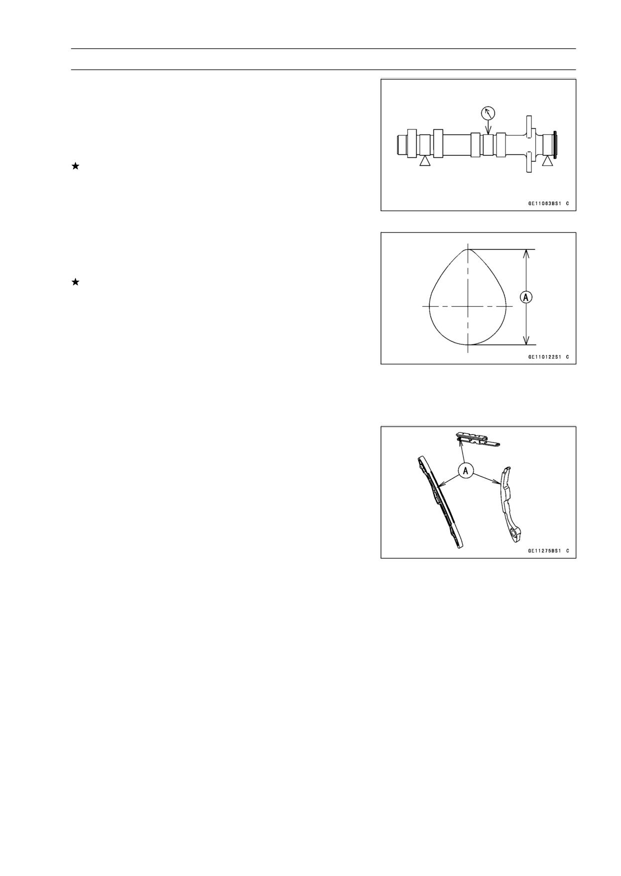
• Set the camshaft in a camshaft alignment jig or on V
blocks.
• Measure the runout with a dial gauge at the specified
place as shown.
If the runout exceeds the service limit, replace the shaft.
Camshaft Runout
Standard:
TIR 0.02 mm (0.0008 in.)
Service Limit: TIR 0.1 mm (0.004 in.)
Cam Wear Inspection
• Remove the camshaft (see Camshaft Removal).
• Measure the height [A] of each cam with a micrometer.
If the cams are worn down past the service limit, replace
the camshaft.
Cam Height
Standard:
Exhaust
32.843 ∼ 32.957 mm (1.2930 ∼ 1.2975 in.)
Inlet
33.843 ∼ 33.957 mm (1.3324 ∼ 1.3369 in.)
Service Limit:
Exhaust
32.74 mm (1.289 in.)
Inlet
33.74 mm (1.328 in.)
Camshaft Chain Guide Wear Inspection
• Visually inspect the rubber [A] on the guide.
• If the rubber is damaged or cut, replace the guides.
5-22 ENGINE TOP END
Cylinder Head
Cylinder Compression Measurement
NOTE
○Use the battery which is fully charged.
• Warm up the engine thoroughly.
• Stop the engine.
• Remove:
Front Seat (see Front Seat Removal in the Frame chap-
ter)
Fuel Tank (see Fuel Tank Removal in the Fuel System
chapter)
Spark Plug (see Spark Plug Replacement in the Periodic
Maintenance chapter)
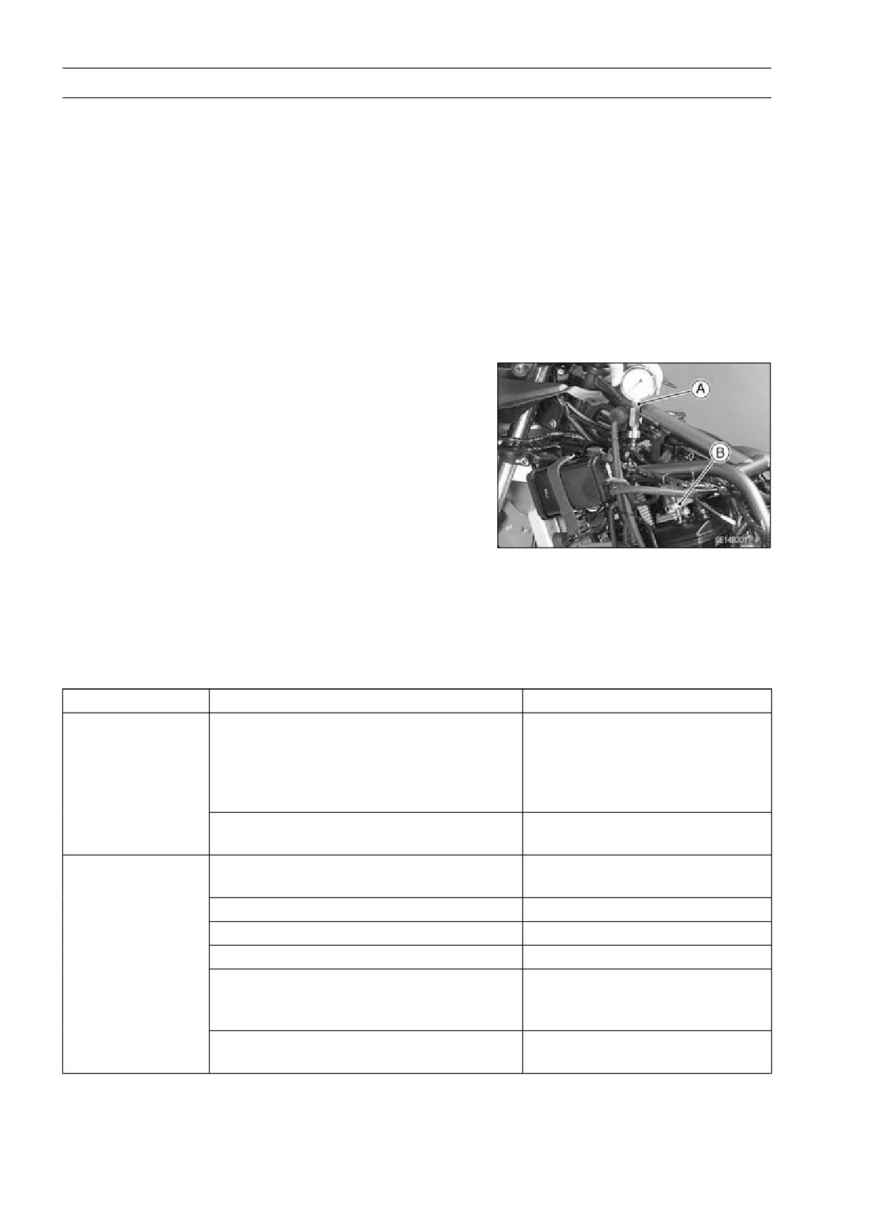
• Attach the compression gauge [A] and adapter [B] firmly
into the spark plug hole.
• Using the starter motor, turn the engine over with the throt-
tle fully open until the compression gauge stops rising; the
compression is the highest reading obtainable.
Special Tools - Compression Gauge, 20 kgf/cm²: 57001-221
Compression Gauge Adapter, M10 × 1.0:
57001-1317
Cylinder Compression
Usable Range: 961 ∼ 1 471 kPa (9.8 ∼ 15.0 kgf/cm², 139
∼ 213 psi) @470r/min (rpm)
• Repeat the measurement for the other cylinder.
• Install the spark plugs.
Torque - Spark Plugs: 13 N·m (1.3 kgf·m, 115 in·lb)
Problem
Diagnosis
Remedy (Action)
Cylinder
Carbon accumulation on piston and in
Remove the carbon deposits
compression is
combustion chamber possibly due to
and replace damaged parts if
higher than usable
damaged valve stem oil seal and/or
necessary.
range
damaged piston oil rings (This may be
indicated by white exhaust smoke.)
Incorrect cylinder head gasket thickness
Replace the gasket with a
standard part.
Cylinder
Gas leakage around cylinder head
Replace damaged gasket and
compression is
check cylinder head warp.
lower than usable
Bad condition of valve seating
Repair if necessary.
range
Incorrect valve clearance
Adjust the valve clearance.
Incorrect piston/cylinder clearance
Replace the piston and/or cylinder
Piston seizure
Inspect the cylinder and
replace/repair the cylinder
and/or piston as necessary.
Bad condition of piston ring and/or piston
Replace the piston and/or the
ring grooves
piston rings.
ENGINE TOP END 5-23
Cylinder Head
Cylinder Head Removal
• Drain the coolant (see Coolant Change in the Periodic
Maintenance chapter).
• Remove:
Lower Fairing (see Lower Fairing Removal in the Frame
chapter)
Fuel Tank (see Fuel Tank Removal in the Fuel System
chapter)
Radiator (see Radiator, Radiator Fan Removal in the
Cooling System chapter)
Muffler (see Muffler Removal)
Camshaft Chain Tensioner (see Camshaft Chain Ten-
sioner Removal)
Left and Right Engine Bracket with Ignition Coils
• Remove:
Cylinder Head Cover
Camshafts
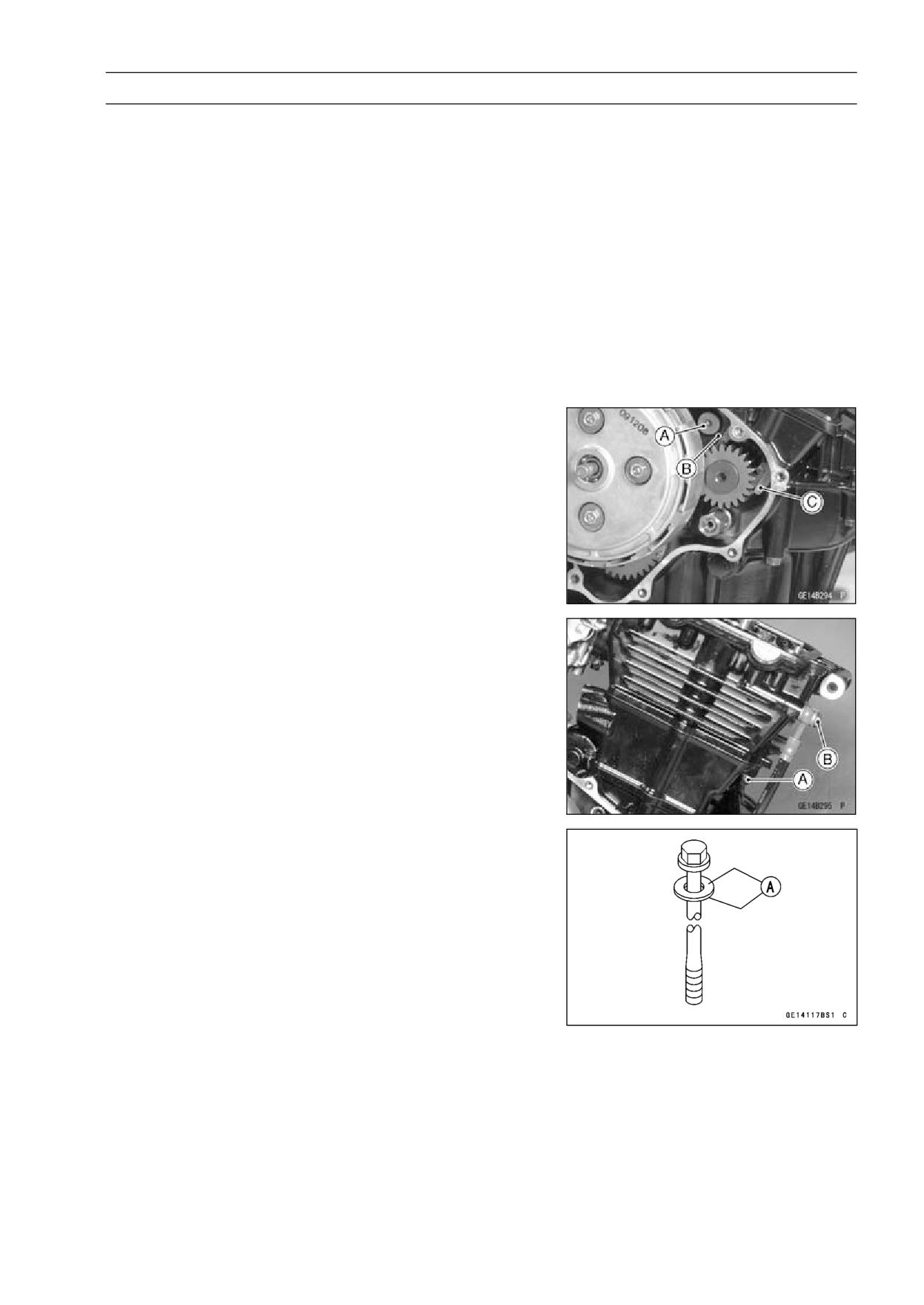
Rear Camshafts Chain Guide Bolt (Lower) [A] and Chain
Guide [B]
Front Camshaft Chain Guide [C]
• Pull out the water pipe.
• Remove the 6 mm cylinder head bolt [A] first, then remove
the 8 mm cylinder head bolts.
• Remove the oil hose banjo bolt [B].
• Before removing the cylinder head, hold the carburetor to
the air cleaner ducts securely.
Cylinder Head Installation
NOTE
○The camshaft cap is machined with the cylinder head,
so if a new cylinder head is installed, use the cap that
is supplied with the new head.
• Install the pin and new cylinder head gasket.
• Apply molybdenum disulfide oil to the both sides [A] of the
8 mm cylinder head bolt washers.
5-24 ENGINE TOP END
Cylinder Head
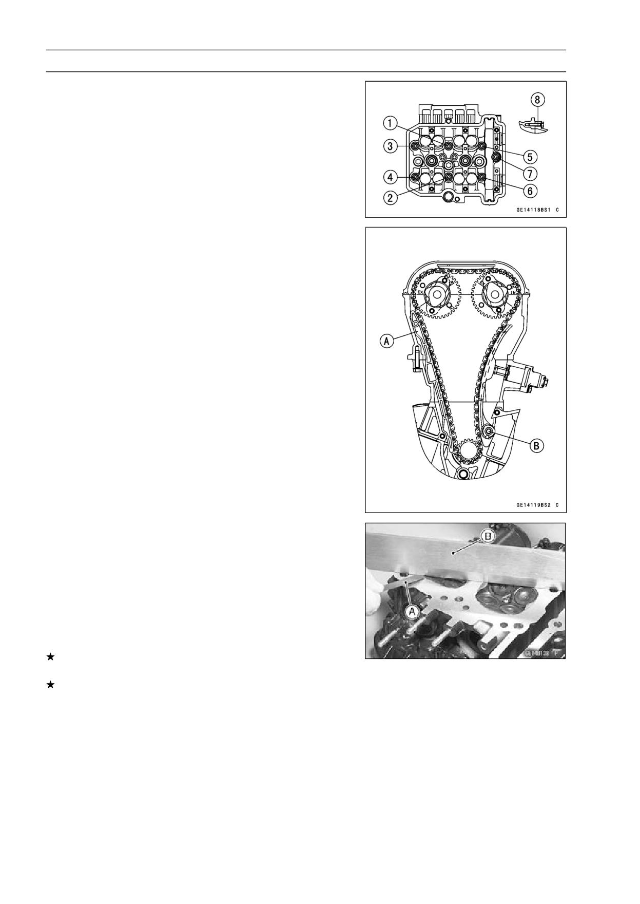
• Tighten the 8 mm cylinder head bolts [1 ∼ 7] following the
tightening sequence.
Torque - Cylinder Head Bolts: 31.4 N·m (3.2 kgf·m, 23 ft·lb)
• Tighten the 6 mm cylinder head bolt [8] following the tight-
ening sequence.
Torque - Cylinder Head Bolts: 12 N·m (1.2 kgf·m, 106 in·lb)
• After cylinder head installation, install the front camshaft
chain guide [A].
• Tighten the rear camshaft chain guide bolt (lower) [B] to
the specified torque.
• Tighten the oil hose banjo bolt to the specified torque.
Torque - Camshaft Chain Guide Bolt (lower): 17 N·m (1.7
kgf·m, 13 ft·lb)
Oil Hose Banjo Bolt: 19.6 N·m (2.0 kgf·m, 14.5 ft·lb)
Cylinder Head Warp Inspection
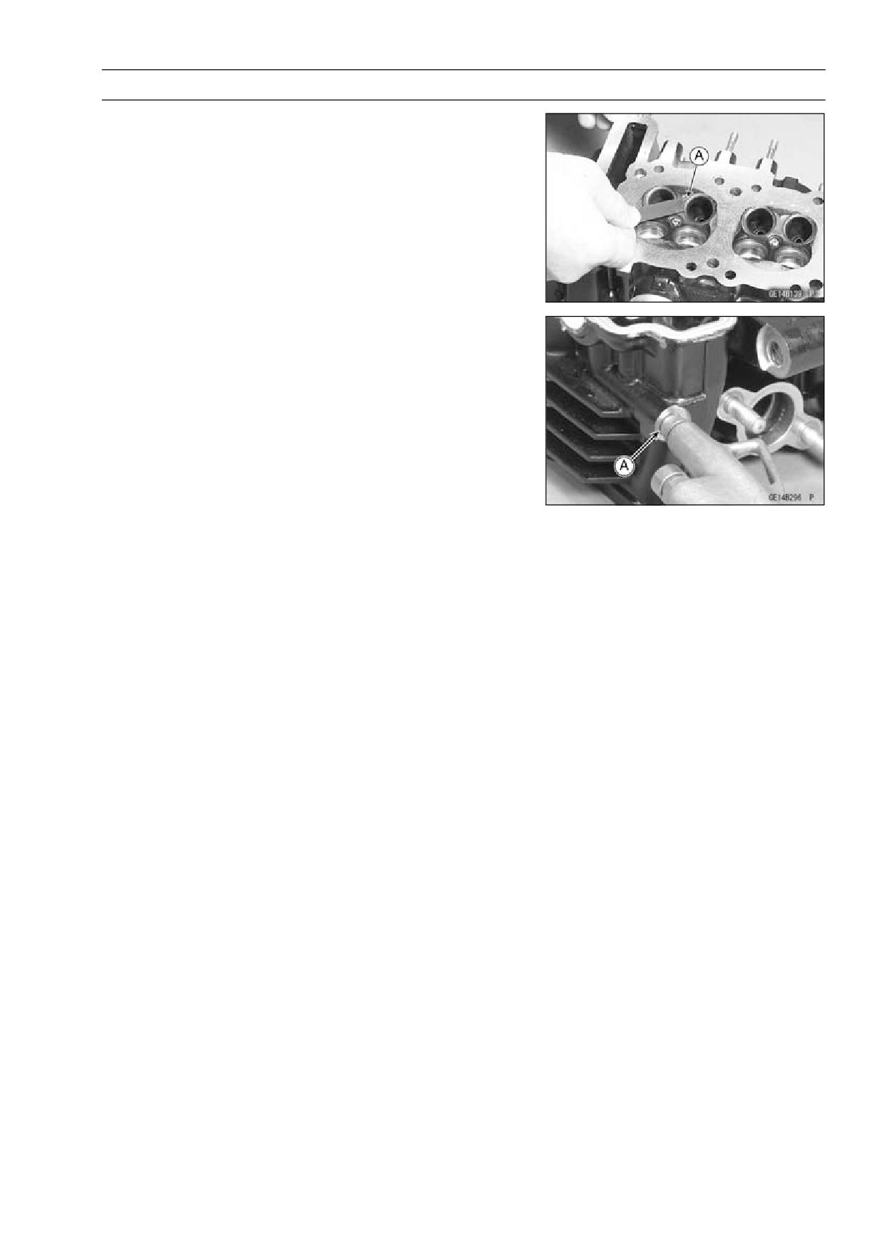
• Lay a straightedge across the lower surface of the cylinder
head at several positions.
• Use a thickness gauge [A] to measure the space between
the straightedge [B] and the head.
Cylinder Head Warp
Standard:
- - -
Service Limit: 0.05 mm (0.002 in.)
If the cylinder head is warped more than the service limit,
replace it.
If the cylinder head is warped less than the service limit,
repair the head by rubbing the lower surface on emery
paper secured to a surface plate (first No. 200, then No.
400).
ENGINE TOP END 5-25
Cylinder Head
Cylinder Head Cleaning
• Remove:
Cylinder Head (see Cylinder Head Removal)
Valves (see Valve Removal)
• Scrape [A] the carbon out of the combustion chamber and
exhaust port with a suitable tool.
• Wash the cylinder head with a high-flash point solvent.
• Using compressed air, blow out any particles which may
obstruct the oil passage [A] in the cylinder head.
• Install the valve (see Valve Installation).
• Install the cylinder head (see Cylinder Head Installation).
5-26 ENGINE TOP END
Valves
Valve Clearance Inspection
• Refer to Valve Clearance Inspection in the Periodic Main-
tenance chapter.
Valve Clearance Adjustment
• Refer to Valve Clearance Adjustment in the Periodic
Maintenance chapter.
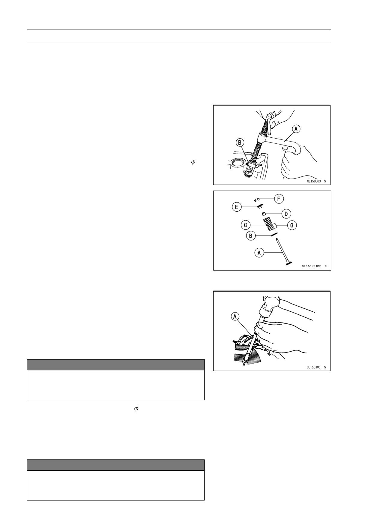
Valve Removal
• Remove the cylinder head (see Cylinder Head Removal).
• Use the valve spring compressor assembly and the
adapter to press down the valve spring retainer.
Special Tools - Valve Spring Compressor Assembly: 57001
-241 [A]
Valve Spring Compressor Adapter,
16:
57001-1305 [B]
Valve Installation
• Replace the oil seal with a new one.
• Apply engine oil to the lip of oil seal.
• Apply a thin coat of molybdenum disulfide grease to the
valve stem before valve installation.
• Install the spring so that the closed coil end faces down-
wards.
[A] Valve Stem
[E] Retainer
[B] Spring Seat
[F] Split Keepers
[C] Spring
[G] Closed Coil End
[D] Oil Seal
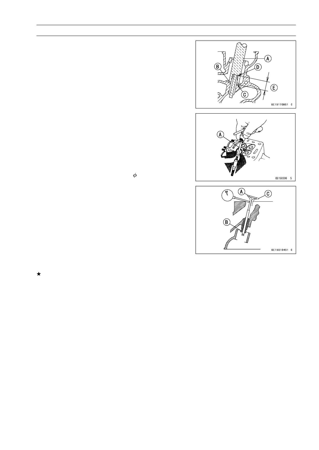
Valve Guide Removal
• Remove:
Valve (see Valve Removal)
Oil Seal
Spring Seat
• Heat the area around the valve guide to 120 ∼ 150°C (248
∼ 302°F), and hammer lightly on the valve guide arbor [A]
to remove the guide from the top of the head.
NOTICE
Do not heat the cylinder head with a torch. This will
warp the cylinder head. Soak the cylinder head in
oil and heat the oil.
Special Tool - Valve Guide Arbor,
4.5: 57001-1331
Valve Guide Installation
• Apply a thin coat of oil to the outer surface of the valve
guide.
• Heat the area around the valve guide up to 120 ∼ 150°C
(248 ∼ 302°F).
NOTICE
Do not heat the cylinder head with a torch. This will
warp the cylinder head. Soak the cylinder head and
heat the oil.
ENGINE TOP END 5-27
Valves
• Using the valve guide driver [A] and washer [B], press
and insert the valve guide in until the washer surface [C]
touches the head surface [D].
15.3 ∼ 15.5 mm (0.60 ∼ 0.61 in.) [E]
Special Tools - Valve Guide Drive: 57001-1564
Washer: 57001-1720
• Wait until the cylinder head cools down and then ream the
valve guide with the valve guide reamer [A] even if the old
guide is reused.
○Turn the reamer in a clockwise direction until the reamer
turns freely in the guide. Never turn the reamer counter-
clockwise or it will be dulled.
○Once the guides are reamed they must be cleaned thor-
oughly.
Special Tool - Valve Guide Reamer,
4.5: 57001-1333
Valve-to-Guide Clearance Measurement (Wobble
Method)
If a small bore gauge is not available, inspect the valve
guide wear by measuring the valve to valve guide clearance
with the wobble method as indicated below.
• Insert a new valve [A] into the guide [B] and set a dial
gauge against the stem perpendicular to it as close as
possible to the cylinder head mating surface.
• Move the stem back and forth [C] to measure valve/valve
guide clearance.
• Repeat the measurement in a direction at a right angle to
the first.
If the reading exceeds the service limit, replace the guide.
NOTE
○The reading is not actual valve/valve guide clearance
because the measuring point is above the guide.
Valve/Valve Guide Clearance (Wobble Method)
Standard:
Inlet
0.03 ∼ 0.09 mm (0.0012 ∼ 0.0035 in.)
Exhaust
0.08 ∼ 0.15 mm (0.0031 ∼ 0.0059 in.)
Service Limit:
Inlet
0.27 mm (0.011 in.)
Exhaust
0.33 mm (0.013 in.)
5-28 ENGINE TOP END
Valves
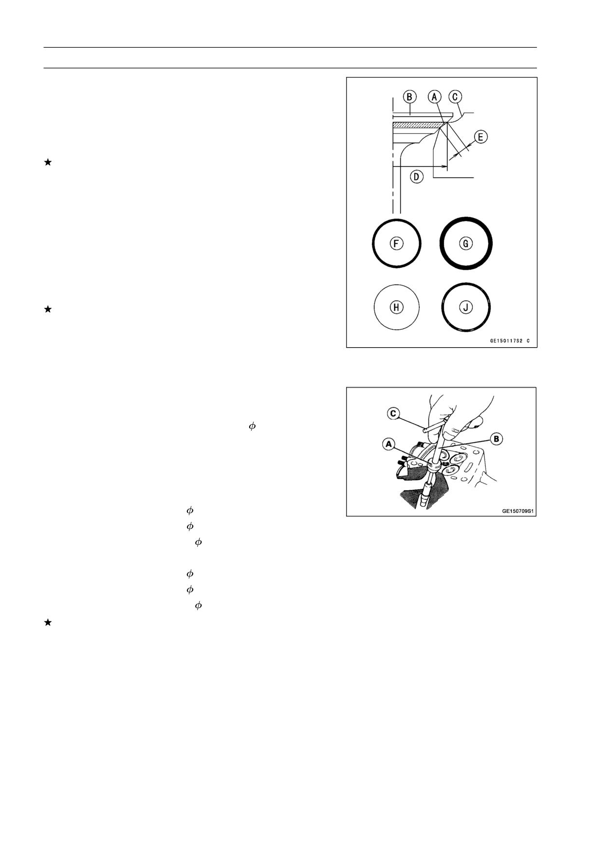
Valve Seat Inspection
• Remove the valve (see Valve Removal).
• Check the valve seating surface [A] between the valve [B]
and valve seat [C].
○Measure the outside diameter [D] of the seating pattern
on the valve seat.
If the outside diameter is too large or too small, repair the
seat (see Seat Repair).
Valve Seating Surface Outside Diameter
Standard:
Inlet
21.9 ∼ 22.1 mm (0.8622 ∼ 0.8701 in.)
Exhaust 19.3 ∼ 19.5 mm (0.7598 ∼ 0.7677 in.)
○Measure the seat width [E] of the portion where there is
no build-up carbon (white portion) of the valve seat with a
vernier caliper.
Good [F]
If the width is too wide [G], too narrow [H] or uneven [J],
repair the seat (see Valve Seat Repair).
Valve Seating Surface Width
Standard:
Inlet, Exhaust
0.5 ∼ 1.0 mm (0.0197 ∼ 0.0394 in.)
Valve Seat Repair
• Repair the valve seat with the valve seat cutters [A].
Special Tools - Valve Seat Cutter Holder,
4.5: 57001-1330
[B]
Valve Seat Cutter Holder Bar: 57001-1128
[C]
For Inlet Valve Seat
Valve Seat Cutter, 45° -
24.5: 57001-1113
Valve Seat Cutter, 32° -
25: 57001-1118
Valve Seat Cutter, 67.5° -
22: 57001-1207
For Exhaust Valve Seat
Valve Seat Cutter, 45° -
24.5: 57001-1113
Valve Seat Cutter, 32° -
22: 57001-1206
Valve Seat Cutter, 67.5° -
22: 57001-1207
If the manufacturer’s instructions are not available, use
the following procedure.
ENGINE TOP END 5-29
Valves
Seat Cutter Operation Cares
1. This valve seat cutter is developed to grind the valve for
repair. Therefore the cutter must not be used for other
purposes than seat repair.
2. Do not drop or shock the valve seat cutter, or the dia-
mond particles may fall off.
3. Do not fail to apply engine oil to the valve seat cutter
before grinding the seat surface. Also wash off ground
particles sticking to the cutter with washing oil.
NOTE
○Do not use a wire brush to remove the metal particles
from the cutter. It will take off the diamond particles.
4. Setting the valve seat cutter holder in position, operate
the cutter in one hand. Do not apply too much force to
the diamond portion.
NOTE
○Prior to grinding, apply engine oil to the cutter and dur-
ing the operation, wash off any ground particles sticking
to the cutter with washing oil.
5. After use, wash it with washing oil and apply thin layer
of engine oil before storing.
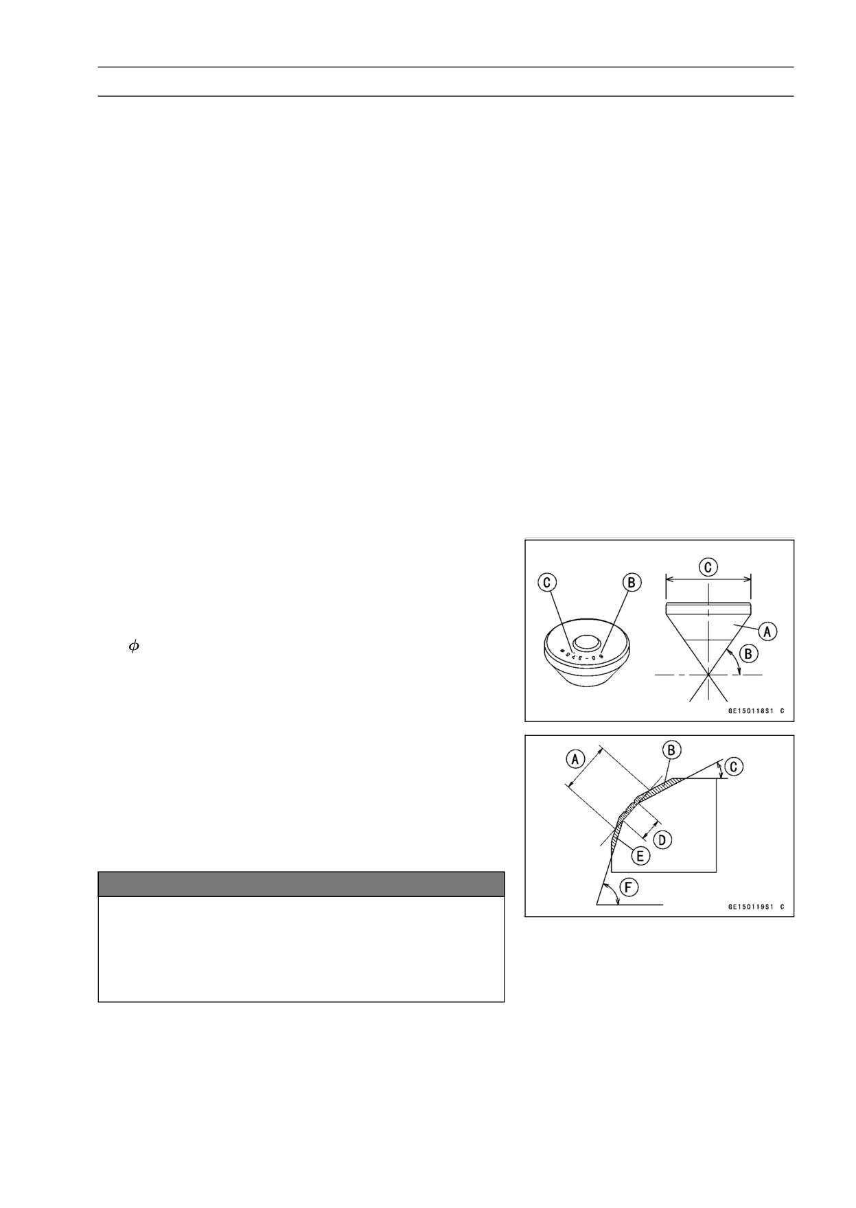
Marks Stamped on the Cutter
The marks stamped on the back of the cutter [A] represent
the following.
60°
Cutter angle [B]
37.5
....................... Outer diameter of cutter [C]
Operating Procedures
• Clean the seat area carefully.
• Coat the seat with machinist’s dye.
• Fit a 45° cutter into the holder and slide it into the valve
guide.
• Press down lightly on the handle and turn it right or left.
Grind the seating surface only until it is smooth.
NOTICE
Do not grind the seat too much. Overgrinding will
reduce valve clearance by sinking the valve into the
head. If the valve sinks too far into the head, it will
be impossible to adjust the clearance, and the cylin-
der head must be replaced.
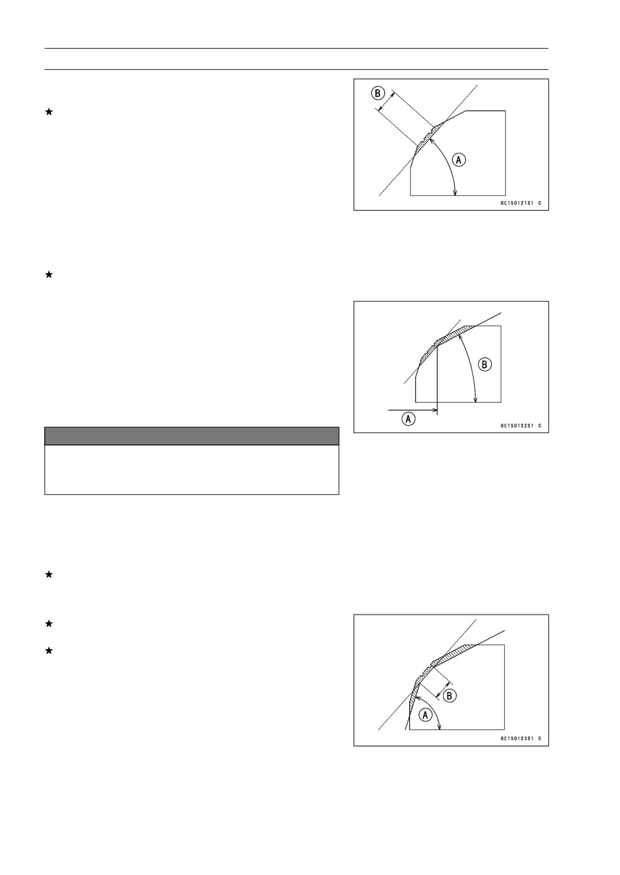
Widened Width [A] of engagement by machining with
45° cutter
Ground Volume [B] by 32° cutter
32° [C]
Correct Width [D]
Ground Volume [E] by 67.5° cutter
67.5° [F]
5-30 ENGINE TOP END
Valves
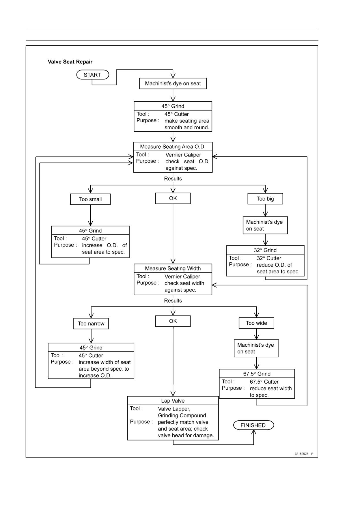
• Measure the outside diameter (O.D.) of the seating sur-
face with a vernier caliper.
If the outside diameter of the seating surface is too small,
repeat the 45° grind [A] until the diameter is within the
specified range.
Original Seating Surface [B]
NOTE
○Remove all pittings of flaws from 45° ground surface.
○After grinding with 45° cutter, apply thin coat of machin-
ist’s dye to seating surface. This makes seating surface
distinct and 32° and 67.5° grinding operation easier.
○When the valve guide is replaced, be sure to grind with
45° cutter for centering and good contact.
If the outside diameter of the seating surface is too large,
make the 32° grind described below.
• If the outside diameter [A] of the seating surface is within
the specified range, measure the seat width as described
below.
• Grind the seat at a 32° angle [B] until the seat O.D. is
within the specified range.
○To make the 32° grind, fit a 32° cutter into the holder, and
slide it into the valve guide.
○Turn the holder one turn at a time while pressing down
very lightly. Check the seat after each turn.
NOTICE
The
32° cutter removes material very quickly.
Check the seat outside diameter frequently to pre-
vent overgrinding.
○After making the 32° grind, return to the seat O.D. mea-
surement step above.
• To measure the seat width, use a vernier caliper to mea-
sure the width of the 45° angle portion of the seat at sev-
eral places around the seat.
If the seat width is too narrow, repeat the 45° grind until
the seat is slightly too wide, and then return to the seat
O.D. measurement step above.
If the seat width is too wide, make the 67.5° [A] grind
described below.
If the seat width is within the specified range, lap the valve
to the seat as described below.
• Grind the seat at a 67.5° angle until the seat width is within
the specified range.
○To make the 67.5° grind, fit a 67.5° cutter into the holder,
and slide it into the valve guide.
○Turn the holder, while pressing down lightly.
○After making the 67.5° grind, return to the seat width mea-
surement step above.
Correct Width [B]
ENGINE TOP END 5-31
Valves
• Lap the valve to the seat, once the seat width and O.D.
are within the ranges specified above.
○Put a little coarse grinding compound on the face of the
valve in a number of places around the valve head.
○Spin the valve against the seat until the grinding com-
pound produces a smooth, matched surface on both the
seat and the valve.
○Repeat the process with a fine grinding compound.
[A] Lapper
[B] Valve Seat
[C] Valve
• The seating area should be marked about in the middle
of the valve face.
If the seat area is not in the right place on the valve, check
to be sure the valve is the correct part. If it is, it may have
been refaced too much; replace it.
• Be sure to remove all grinding compound before assem-
bly.
• When the engine is assembled, be sure to adjust the valve
clearance (see Engine Top End in the Periodic Mainte-
nance chapter).
5-32 ENGINE TOP END
Valves
ENGINE TOP END 5-33
Cylinder, Pistons
Cylinder Removal
• Remove:
Cylinder Head (see Cylinder Head Removal)
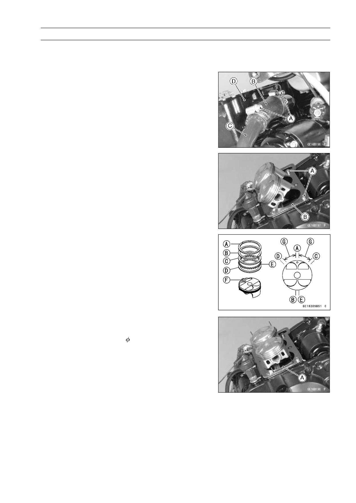
• Loosen the clamps [A], and take off the water hose [B]
and pipe [C].
• Remove the cylinder [D].
Cylinder Installation
NOTE
○If a new cylinder is used, use a new piston ring.
• Install the dowel pins [A] and new cylinder gasket [B].
• Apply molybdenum disulfide oil solution to the cylinder
bore, piston rings and pistons.
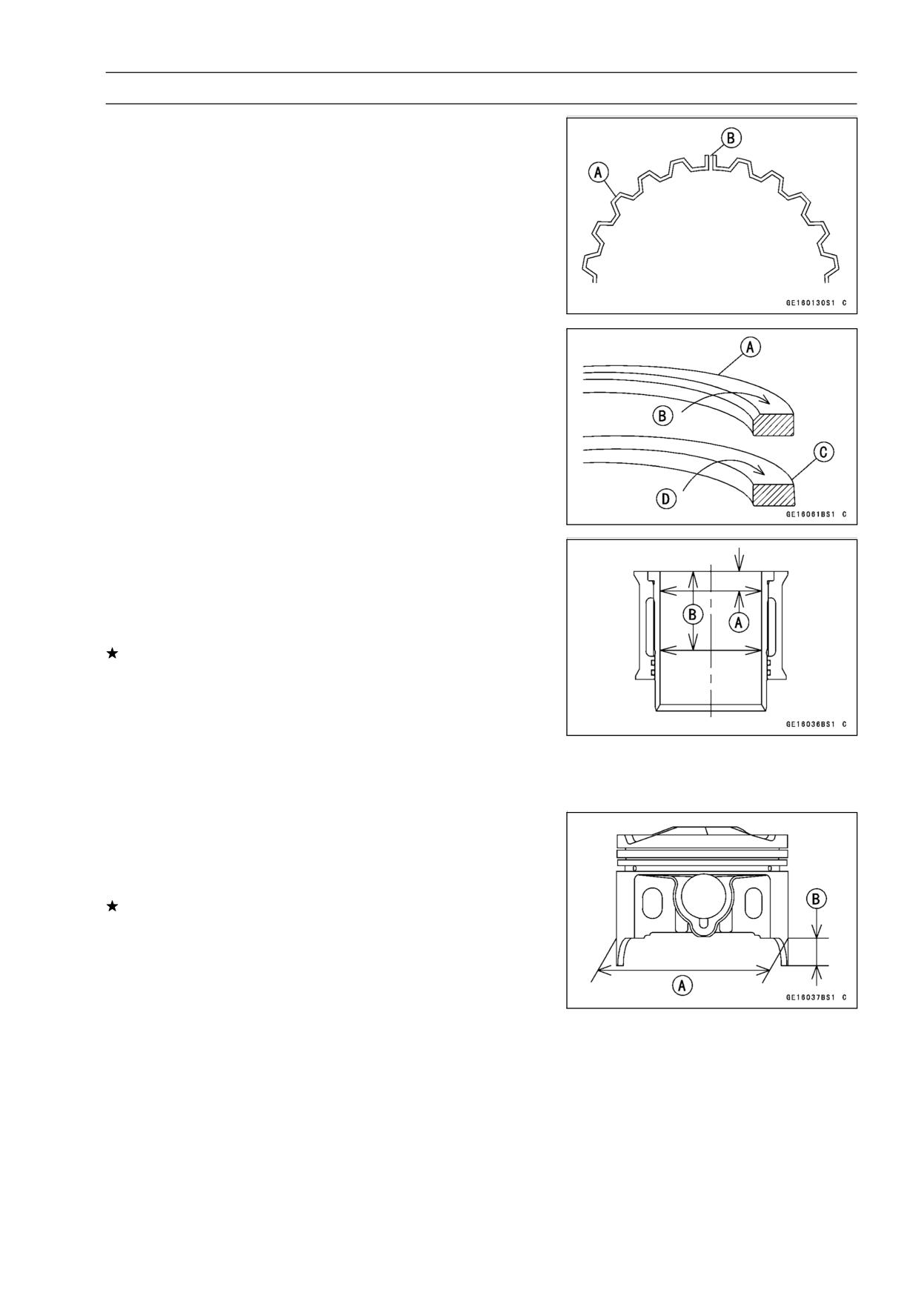
• The piston ring openings must be positioned as shown in
the figure. The openings of the oil ring steel rails must be
about 30 ∼ 40° of angle from the opening of the top ring.
[A] Top Ring
[B] Second Ring
[C] Oil Ring Steel Rail (Upper)
[D] Oil Ring Steel Rail (Lower)
[E] Oil Ring Expander
[F] Arrow Mark
[G] 30 ∼ 40°
• Slip the piston base [A] as shown to hold piston level, and
install the cylinder.
Special Tool - Piston Base,
2.3: 57001-1336
5-34 ENGINE TOP END
Cylinder, Pistons
Piston Removal
• Remove the cylinder (see Cylinder Removal).
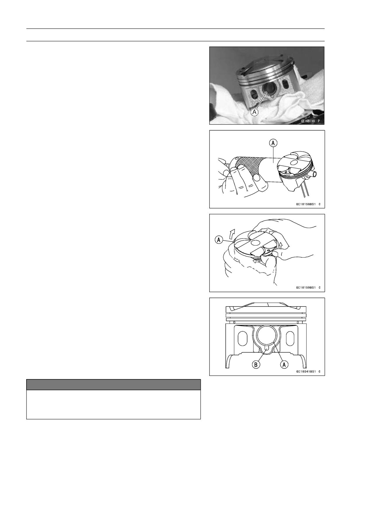
• Place a clean cloth under the pistons and remove the pis-
ton pin snap ring [A] from the outside of each piston.
• Remove the piston pins.
Special Tool - Piston Pin Puller Assembly: 57001-910 [A]
• Remove the pistons.
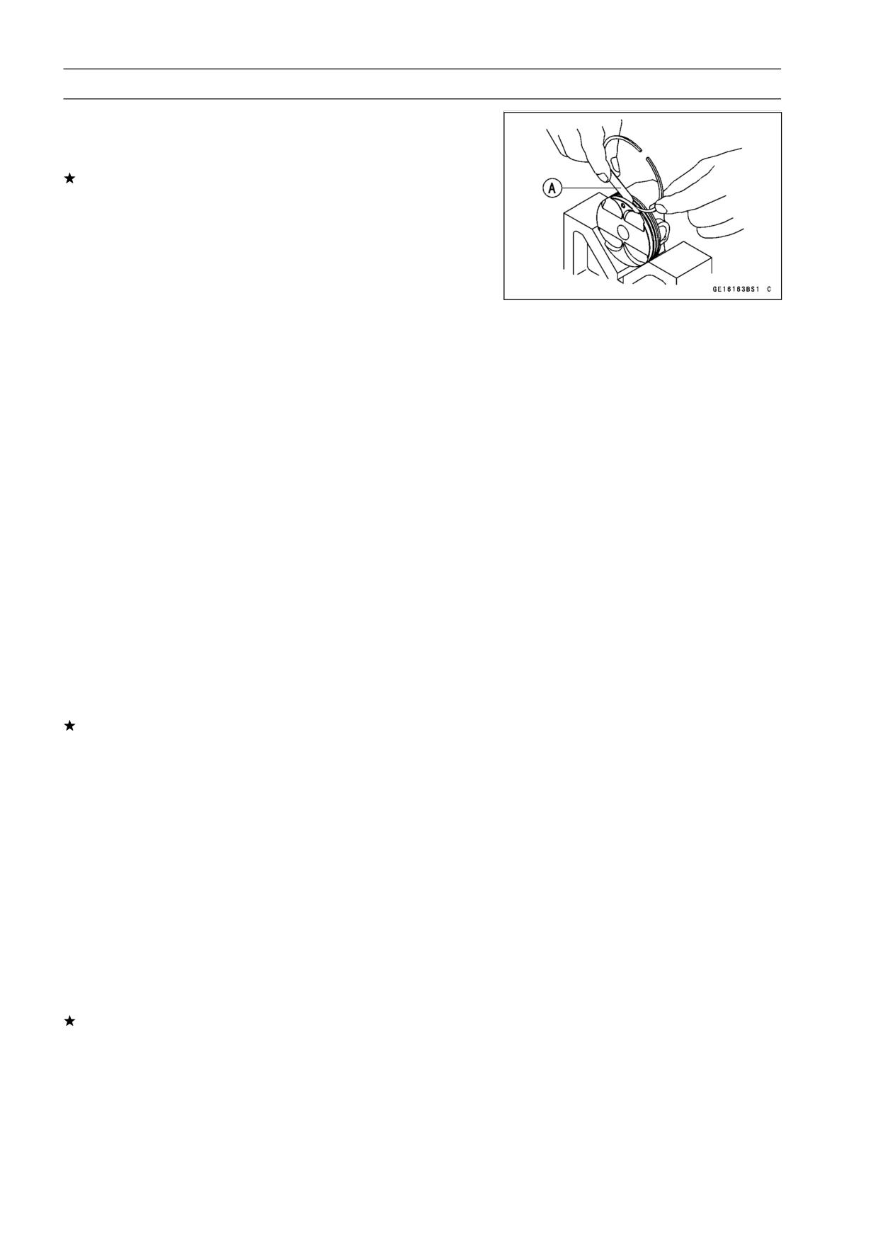
• Carefully spread the ring opening with your thumbs and
then push up on the opposite side of the ring [A] to remove
it.
• Remove the 3-piece oil ring with your thumbs in the same
manner.
Piston Installation
NOTE
○If a new piston is used, use a new piston ring.
• Install the piston with its marking dent facing forward.
• Fit a new piston pin snap ring into the side of the piston
so that the ring opening [A] does not coincide with the slit
[B] of the piston pin hole.
○When installing the piston pin snap ring, compress it only
enough to install it and no more.
NOTICE
Do not reuse snap rings, as removal weakens and
deforms them.
They could fall out and score the cylinder wall.
ENGINE TOP END 5-35
Cylinder, Pistons
• Install the oil ring expander [A] in the bottom piston ring
groove so the ends [B] butt together.
• Install the oil ring steel rails, one above the expander and
one below it.
○Spread the rail with your thumbs, but only enough to fit
the rail over the piston.
○Release the rail into the bottom piston ring groove.
NOTE
○The oil ring rails have no “top” or “bottom”.
• Do not mix up the top and second ring.
• Install the top ring [A] so that the “R” mark [B] faces up.
• Install the second ring [C] so that the “RN” mark [D] faces
up.
○Apply molybdenum disulfide oil solution to the piston
rings.
Cylinder Wear Inspection
• Since there is a difference in cylinder wear in different di-
rections, take a side-to-side and a front-to-back measure-
ment at each of the two locations (total of four measure-
ments) shown in the figure.
If any of the cylinder inside diameter measurements ex-
ceeds the service limit, replace the cylinder.
[A] 10 mm
[B] 60 mm
Cylinder Inside Diameter
Standard:
62.000 ∼ 62.012 mm (2.4409 ∼ 2.4414 in.)
Service Limit:
62.10 mm (2.44 in.)
Piston Wear Inspection
• Measure the outside diameter [A] of each piston 5 mm
(0.20 in.) [B] up from the bottom of the piston at a right
angle to the direction of the piston pin.
If the measurement is under service limit, replace the pis-
ton.
Piston Diameter
Standard:
61.942 ∼ 61.957 mm (2.4387 ∼ 2.4392 in.)
Service Limit:
61.80 mm (2.43 in.)
5-36 ENGINE TOP END
Cylinder, Pistons
Piston Ring, Piston Ring Groove Wear Inspection
• Check for uneven groove wear by inspecting the ring seat-
ing.
The rings should fit perfectly parallel to groove surfaces.
If not, replace the piston and all the piston rings.
• With the piston rings in their grooves, make several mea-
surements with a thickness gauge [A] to determine piston
ring/groove clearance.
Piston Ring/Groove Clearance
Standard:
Top
0.03 ∼ 0.07 mm (0.0012 ∼ 0.0028 in.)
Second
0.02 ∼ 0.06 mm (0.0008 ∼ 0.0024 in.)
Service Limit:
Top
0.17 mm (0.0067 in.)
Second
0.16 mm (0.0063 in.)
Piston Ring Groove Width Inspection
• Measure the piston ring groove width.
○Use a vernier caliper at several points around the piston.
Piston Ring/Groove Width
Standard:
Top
0.82 ∼ 0.84 mm (0.0323 ∼ 0.0331 in.)
Second
0.81 ∼ 0.83 mm (0.0319 ∼ 0.0327 in.)
Oil
1.51 ∼ 1.53 mm (0.0594 ∼ 0.0602 in.)
Service Limit:
Top
0.92 mm (0.0362 in.)
Second
0.91 mm (0.0358 in.)
Oil
1.61 mm (0.0634 in.)
If the width of any two grooves is wider than the service
limit at any point, replace the piston.
Piston Ring Thickness Inspection
• Measure the piston ring thickness.
○Use the micrometer to measure at several points around
the ring.
Piston Ring Thickness
Standard:
Top
0.77 ∼ 0.79 mm (0.0303 ∼ 0.0311 in.)
Second
0.77 ∼ 0.79 mm (0.0303 ∼ 0.0311 in.)
Service Limit:
Top
0.70 mm (0.028 in.)
Second
0.70 mm (0.028 in.)
If any of the measurements is less than the service limit
on either of the rings, replace all the rings.
NOTE
○When using new rings in a used piston, check for un-
even groove wear. The rings should fit perfectly parallel
to the groove sides. If not, replace the piston.
ENGINE TOP END 5-37
Cylinder, Pistons
Piston Ring End Gap Inspection
• Place the piston ring [A] inside the cylinder, using the pis-
ton to locate the ring squarely in place. Set it close to the
bottom of the cylinder, where cylinder wear is low.
• Measure the gap [B] between the ends of the ring with a
thickness gauge.
Piston Ring End Gap
Standard:
Top
0.15 ∼ 0.30 mm (0.0059 ∼ 0.0118 in.)
Second
0.40 ∼ 0.55 mm (0.0157 ∼ 0.0217 in.)
Oil
0.20 ∼ 0.80 mm (0.0079 ∼ 0.0315 in.)
Service Limit:
Top
0.6 mm (0.024 in.)
Second
0.9 mm (0.035 in.)
Oil
1.1 mm (0.043 in.)
If the end gap of either ring is greater than the service
limit, replace all the rings.
Boring, Honing
When boring and honing a cylinder, note the following:
○There is one size of oversize piston available. Oversize
piston require oversize rings.
Oversize Pistons and Rings
+0.5 mm (0.020 in.)
○Before boring a cylinder, first measure the exact diameter
of the oversize piston, and then, according to the stan-
dard clearance in the Specifications section, determine
the rebore diameter. However, if the amount of boring
necessary would make the inside diameter greater than
0.5 mm (0.002 in.) oversize, the cylinder block must be
replaced.
○Cylinder inside diameter must not vary more than 0.01
mm (0.0004 in.) at any point.
○Be wary of measurements taken immediately after boring
since the heat affects cylinder diameter.
○In the case of a rebored cylinder and oversize piston, the
service limit for the cylinder is the diameter that the cylin-
der was bored to plus 0.1 mm (0.004 in.) and the service
limit for the piston is the oversize piston original diameter
minus 0.15 mm (0.006 in.). If the exact figure for the re-
bored diameter is unknown, it can be roughly determined
by measuring the diameter at the base of the cylinder.
○Never separate the liner from the cylinder, because the
top surface of cylinder and liner is machined at the factory
as an assembly.
5-38 ENGINE TOP END
Carburetor Holder
Carburetor Holder Installation
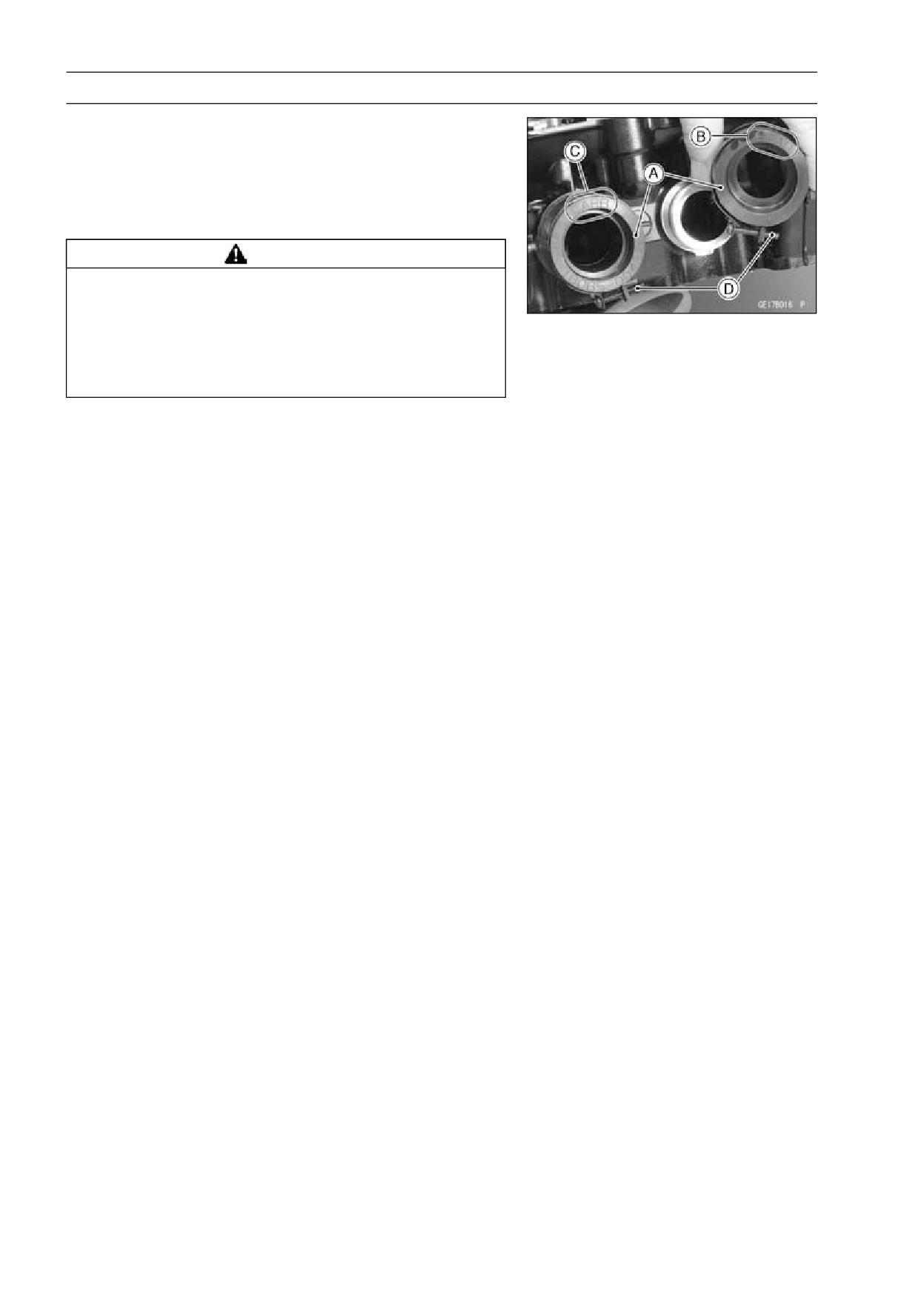
• Install the carburetor holders [A] so that the “HEAD” marks
[B] faces forward (cylinder head side), and “CARB” mark
[C] faces backward (carburetor side).
• Install the holder clamps as shown being careful of the
screw [D] position and the screw head direction.
WARNING
Interference with the vacuum adjusting screws
can result in an unsafe riding condition and cause
a crash resulting in serious injury or death. In-
stall the clamp screws horizontally, otherwise the
screws could come in contact with vacuum adjust-
ing screws.
ENGINE TOP END 5-39
Muffler
Muffler Removal
• Remove:
Lower Fairings (see Lower Fairing Removal in the Frame
chapter)
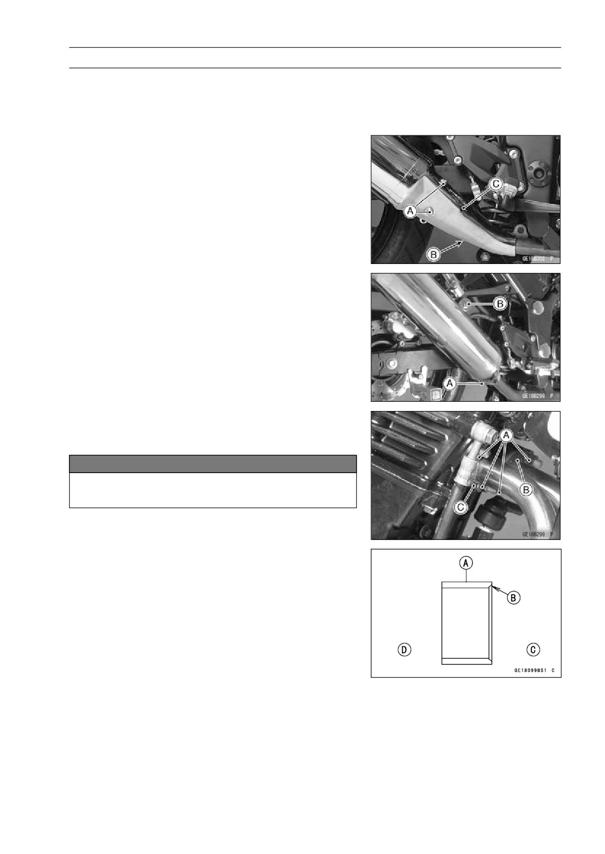
• Remove:
Muffler Cover Bolts [A]
Muffler Cover Clamp Bolt [B]
Muffler Cover [C]
• Loosen the muffler clamp bolt [A] until the clamp turns
freely on the muffler.
• Remove the muffler mounting bolt [B] and nut at the rear
footpeg bracket, and take off the muffler.
• Remove the exhaust pipe holder nuts [A].
• Pull the exhaust pipe toward the front and remove it.
• Remove the gaskets from the exhaust pipe.
NOTICE
Be careful not to touch the radiator fins during
work. The fins are easily deformed.
Muffler Installation
• Smear a little grease on a new exhaust pipe gasket and
stick it into the exhaust port in the cylinder head.
• Attach the exhaust pipe loosely to the cylinder head.
○Position the exhaust pipe in the exhaust port.
• Install the gasket [A] so that its chamfer side [B] faces
manifold side.
Manifold Side [C]
Muffler Side [D]
• Slip the muffler into place from the rear of the frame so
that it fits over the exhaust pipe.
• Hold the muffler up and install the mounting bolts not to
tighten them securely.
• Tighten the exhaust pipe holder nuts evenly and securely.
• Tighten the muffler mounting bolt securely.
Torque - Exhaust Pipe Mounting Bolt: 9.8 N·m (1.0 kgf·m,
87 in·lb)
Exhaust Pipe Holder Nuts: 12 N·m (1.2 kgf·m, 104
in·lb)
Muffler Body Mounting Bolt: 30 N·m (3.1 kgf·m, 22
ft·lb)
5-40 ENGINE TOP END
Muffler
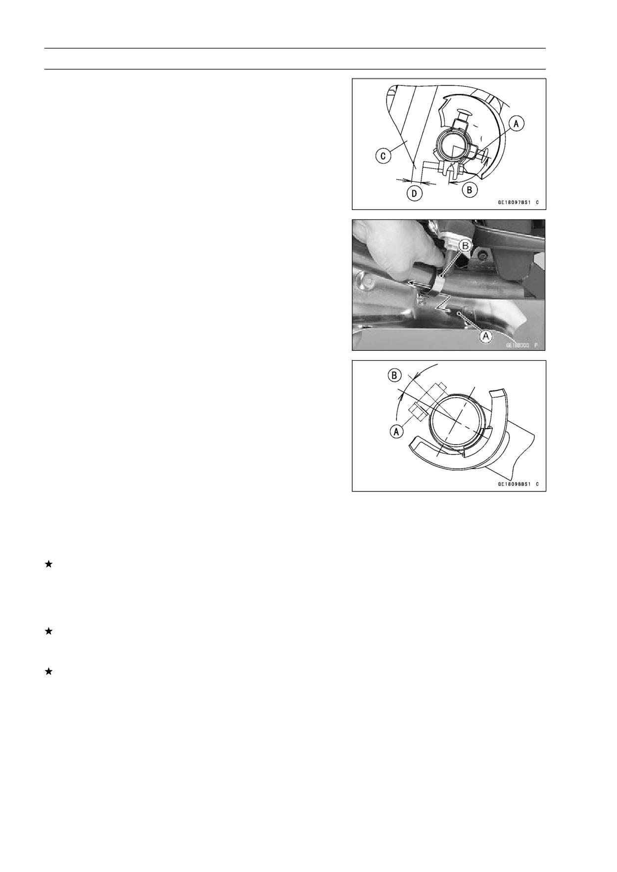
• Tighten the muffler clamp bolt [A] securely waving the di-
rection of the clamp bolts.
74° ∼ 84° [B]
Torque - Muffler Body Clamp Bolt: 17 N·m (1.7 kgf·m, 13
ft·lb)
○Be sure that the distance between the clamp bolt end and
the swingarm [C] is more than 15 mm [D].
• Insert the claw [A] into the cover clamp [B] and tighten the
clamp screw securely.
Torque - Muffler Cover Clamp Screw: 6.9 N·m (0.70 kgf·m,
61 in·lb)
Muffler Cover Bolts: 9.8 N·m (1.0 kgf·m, 87 in·lb)
○Be sure that the position of muffler cover clamp screw [A]
is as shown.
approx. 15° [B]
Exhaust System Inspection
• Before removing the exhaust system, check for signs of
leakage at the exhaust pipe gasket in the cylinder head
and at the muffler clamp.
If there are signs of leakage around the exhaust pipe gas-
ket, it should be replaced. If the muffler to exhaust pipe
joint leaks, tighten the clamp.
• Remove the exhaust system (see Muffler Removal).
• Inspect the gasket for damage and signs of leakage.
If the gasket is damaged or has been leaking, replace it.
• Check the exhaust pipe and muffler for dents, cracks, rust
and holes.
If the exhaust pipe or muffler is damaged or holes, it
should be replaced for best performance and least noise.
CLUTCH 6-1
Clutch
Table of Contents
Exploded View
6-2
Specifications
6-4
Special Tool and Sealant
6-5
Clutch Lever and Cable
6-6
Clutch Lever Free Play Inspection
6-6
Clutch Lever Free Play Adjustment
6-6
Clutch Cable Removal
6-6
Clutch Cable Lubrication
6-6
Clutch Lever Removal
6-6
Clutch Cover
6-7
Clutch Cover Removal
6-7
6
Clutch Cover Installation Note
6-7
Clutch Release Shaft Removal
6-7
Clutch Release Shaft Installation
6-7
Clutch
6-8
Clutch Removal
6-8
Clutch Installation
6-8
Clutch Plate Wear and Damage Inspection
6-9
Clutch Plate Warp Inspection
6-9
Clutch Spring Free Length Inspection
6-10
Clutch Housing Finger Damage Inspection
6-10
Clutch Hub Spline Damage Inspection
6-10
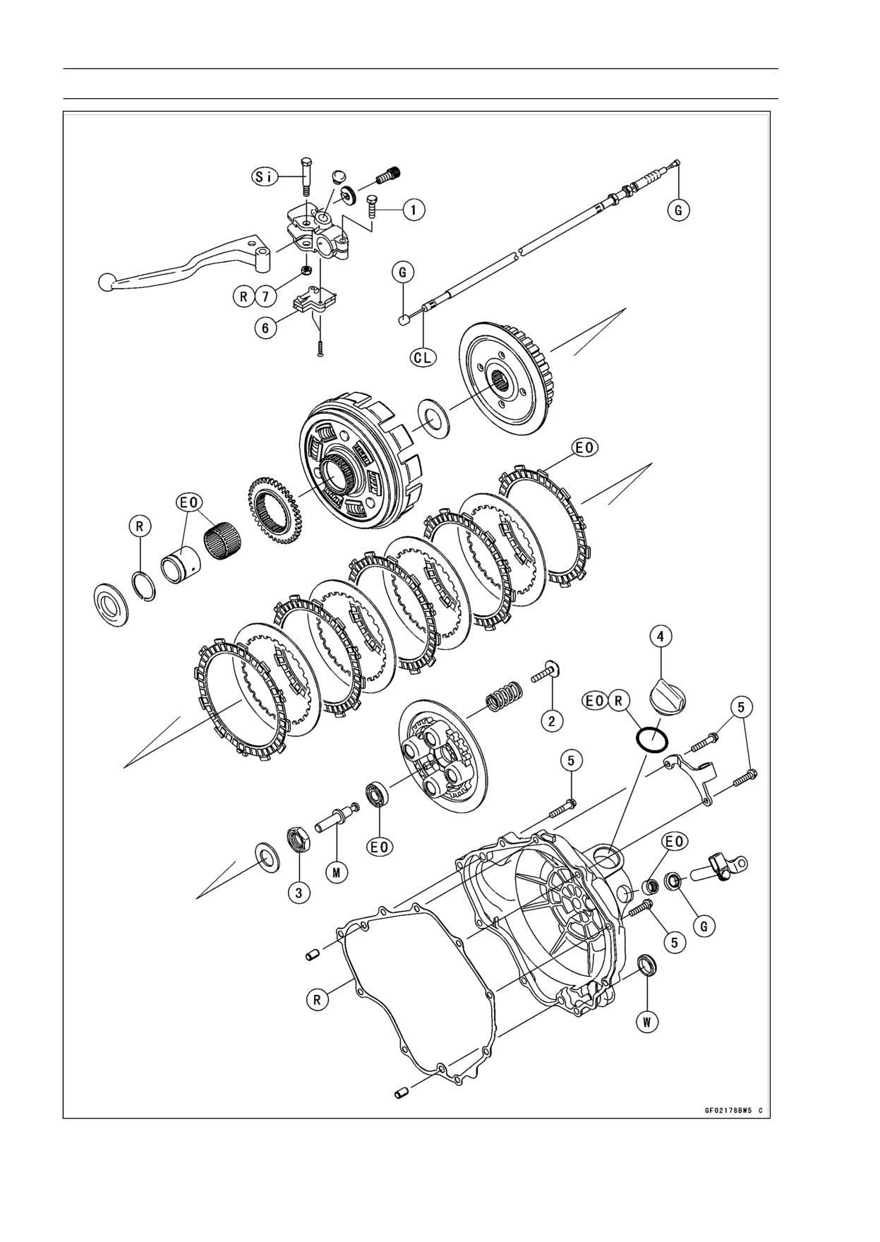
6-2 CLUTCH
Exploded View
CLUTCH 6-3
Exploded View
Torque
No.
Fastener
Remarks
N·m
kgf·m
ft·lb
1
Clutch Lever Holder Clamp Bolts
8.8
0.9
78 in·lb
2
Clutch Spring Bolts
8.8
0.9
78 in·lb
3
Clutch Hub Nut
132
13.5
97.4
4
Oil Filler Plug
-
-
-
Hand-Tighten
5
Clutch Cover Bolts
9.8
1.0
87 in·lb
6. Starter Lockout Switch
7. Clutch Lever Pivot Nut
CL: Apply cable lubricant.
EO: Apply engine oil.
G: Apply grease.
M: Apply molybdenum disulfide grease.
R: Replacement Parts
Si: Apply silicone grease.
W: Apply water.
6-4 CLUTCH
Specifications
Item
Standard
Service Limit
Clutch
Clutch Lever Play
2 ∼ 3 mm (0.08 ∼ 0.12 in.)
- - -
Clutch Spring Free Length
39.4 mm (1.55 in.)
37.6 mm (1.48 in.)
Friction Plate Thickness
2.92 ∼ 3.08 mm (0.115 ∼ 0.121 in.)
2.6 mm (0.10 in.)
Friction and Steel Plate Warp
0.15 mm (0.0059 in.) or less
0.3 mm (0.012 in.)
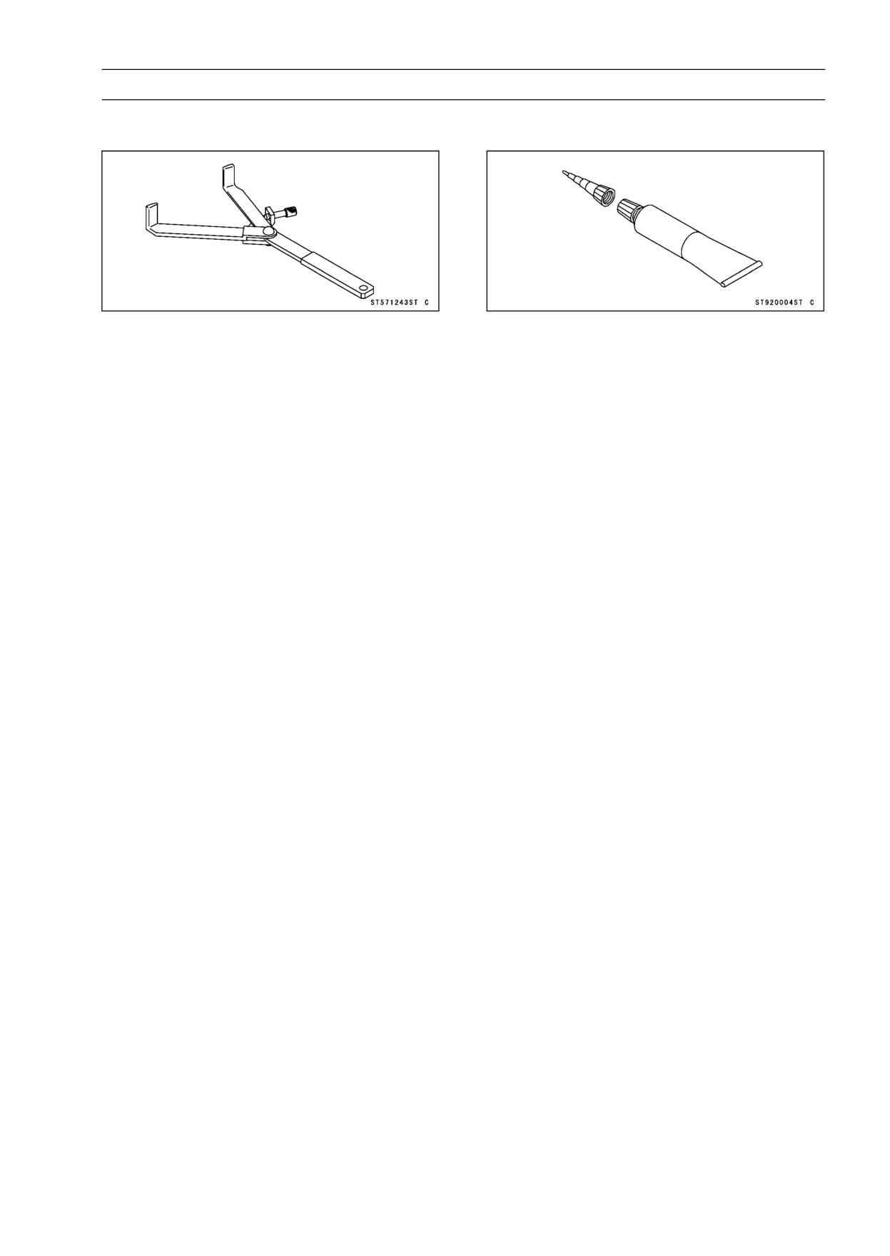
CLUTCH 6-5
Special Tool and Sealant
Clutch Holder:
Liquid Gasket, TB1211F:
57001-1243
92104-0004
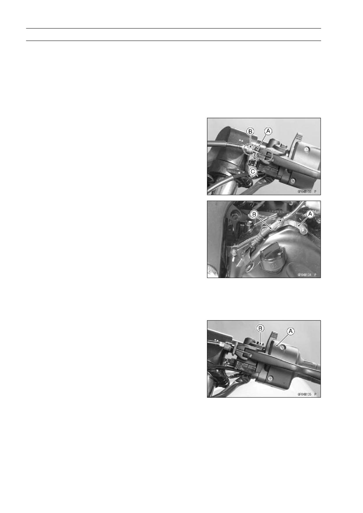
6-6 CLUTCH
Clutch Lever and Cable
Clutch Lever Free Play Inspection
• Refer to Clutch Operation Inspection in the Periodic Main-
tenance chapter (see Clutch Operation Inspection in the
Periodic Maintenance chapter).
Clutch Lever Free Play Adjustment
• Refer to Clutch Operation Inspection in the Periodic Main-
tenance chapter (see Clutch Operation Inspection in the
Periodic Maintenance chapter).
Clutch Cable Removal
• Remove:
Right Lower Fairing (see Lower Fairing Removal in the
Frame chapter)
• Loosen the knurled locknut [A] at the clutch lever, and
screw in the adjuster [B].
• Line up the slots [C] in the clutch lever, locknut, and ad-
juster and then free the cable from the lever.
• Remove the lower cable adjuster of clutch cable from the
cable holder [A] loosening the cable adjuster lock nuts [B].
• Free the clutch inner cable tip from the clutch release
lever.
Clutch Cable Lubrication
• Refer to Chassis Parts Lubrication in the Periodic Mainte-
nance chapter (see Chassis Parts Lubrication in the Pe-
riodic Maintenance chapter).
Clutch Lever Removal
• Remove the upper end of clutch cable.
• Remove the left switch housing [A].
• Remove the clutch lever mounting bolt [B] and nut, and
remove the clutch lever.
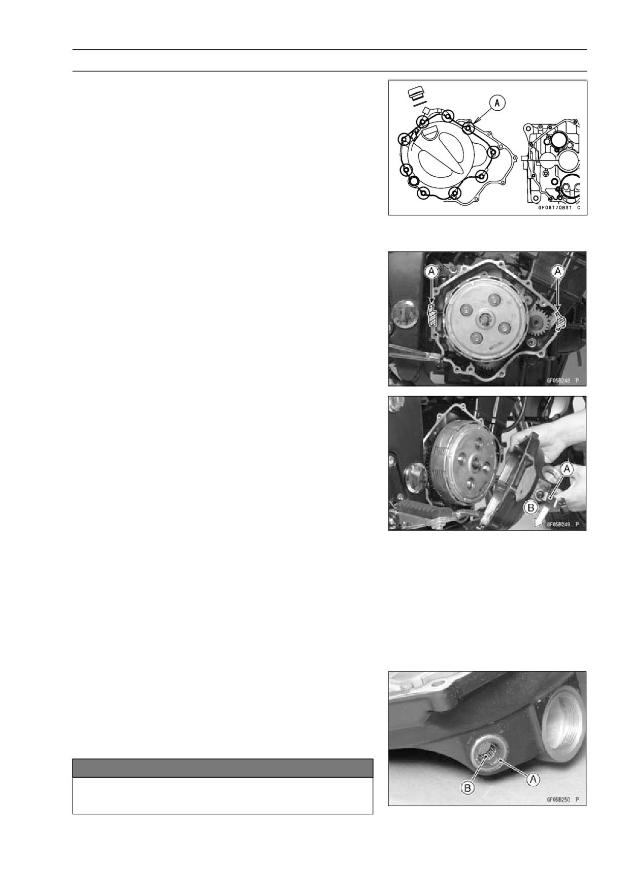
CLUTCH 6-7
Clutch Cover
Clutch Cover Removal
• Drain the engine oil (see Engine Oil Change in the Peri-
odic Maintenance chapter).
• Remove:
Right Lower Fairing (see Lower Fairing Removal in the
Frame chapter)
Clutch Cable (see Clutch Cable Removal)
Oil Filler Plug
• Remove the clutch cover mounting bolts [A] and the clutch
cable guide.
• Turn the clutch release lever couterclockwise fully to re-
lease the clutch release shaft.
Clutch Cover Installation Note
• Scrape the old gasket from the surface of clutch cover and
crankcase, and apply liquid gasket on the mating surface
[A] of the crankcases.
• Install the new clutch cover gasket.
Sealant - Liquid Gasket, TB1211F: 92104-0004
• Turn the clutch release lever [A] counterclockwise fully [B]
and install the clutch cover.
Clutch Release Shaft Removal
• Remove:
Clutch Cable (see Clutch Cable Removal)
Clutch Cover (see Clutch Cover Removal)
• Pull out the clutch release shaft from the clutch cover.
NOTE
○Do not damage the oil seal when it shall be inserted into
the clutch cover hole.
Clutch Release Shaft Installation
• Apply engine oil to the oil seal [A] and needle bearing [B].
• Insert the clutch release shaft into the clutch cover hole.
• Install:
Clutch Cover (see Clutch Cover Installation)
Clutch Cable (see Clutch Cable Installation)
NOTICE
When inserting the release shaft, be careful not to
remove the spring of the oil seal.
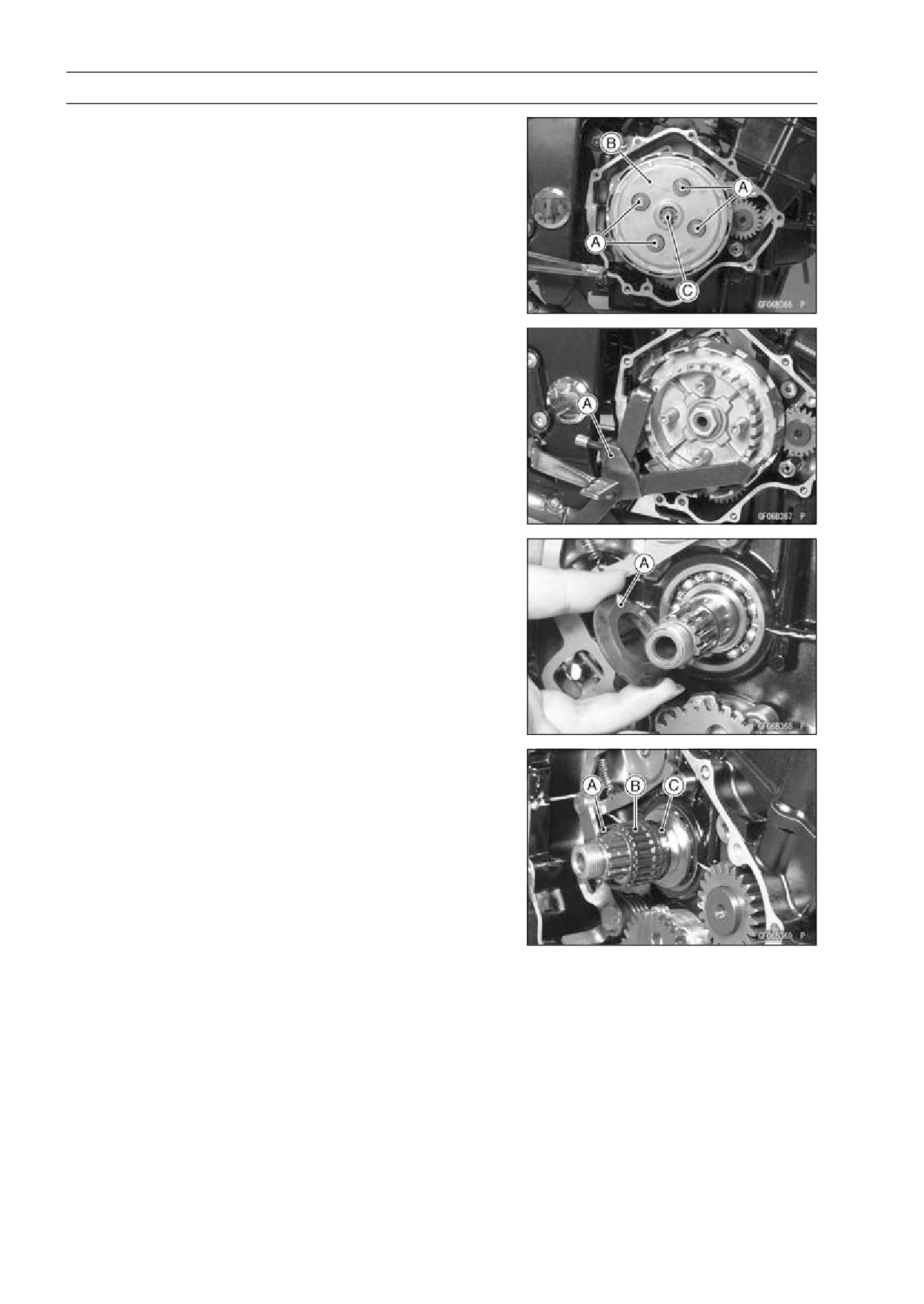
6-8 CLUTCH
Clutch
Clutch Removal
• Remove:
Clutch Cable (see Clutch Cable Removal)
Clutch Cover (see Clutch Cover Removal)
• Remove the clutch spring mounting bolts [A], springs,
clutch operating plate [B] with the clutch push rod [C].
• Remove the clutch steel plates and friction plates.
• Remove the clutch hub nut using the special tool [A].
• Remove the washer, clutch housing, needle bearing,
bushing and the thrust spacer.
Special Tool - Clutch Holder: 57001-1243
Clutch Installation
• Install the thrust spacer [A] so that the chamfer side of it
faces to inside of the engine.
• Install the spacer bushing [A] and needle bearing [B].
○Install the snap ring [C] on the bushing so that it faces to
inside of the engine.
• Install the clutch housing, clutch hub, washer and the
clutch hub nut.
• Tighten the clutch hub nut with the specified torque.
Special Tool - Clutch Holder: 57001-1243
Torque - Clutch Hub Nut: 132 N·m (13.5 kgf·m, 97.4 ft·lb)
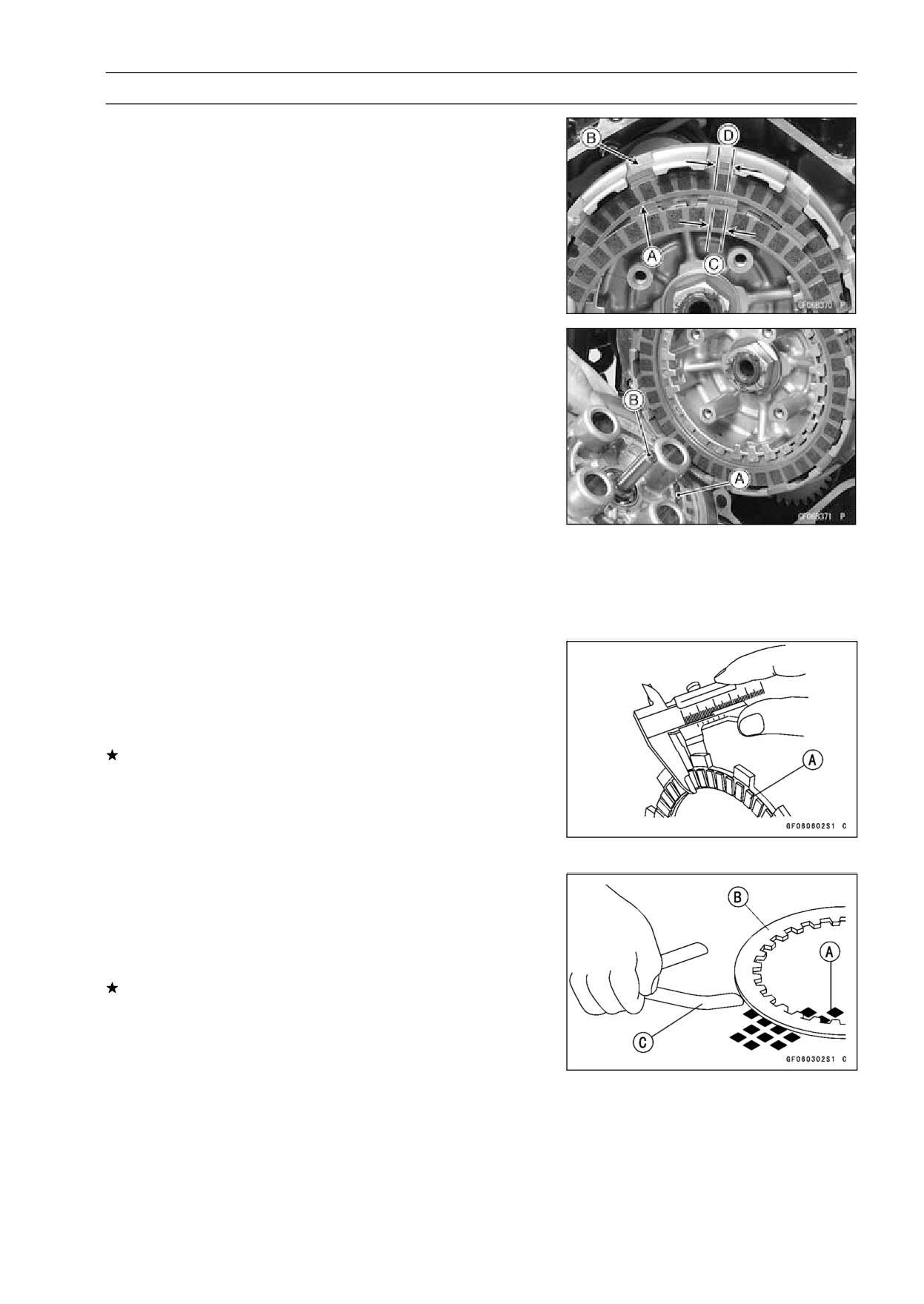
CLUTCH 6-9
Clutch
• Install the friction plate first and clutch steel plate, and
afterward install them alternately.
○The outer-end [A] and inner-end [B] friction plate blocks
are wider than the others.
Wider [C]
Narrower [D]
• Install the clutch operating plate [A] with the clutch push
rod [B].
• Install the springs and tighten the clutch spring bolts with
specified torque.
Torque - Clutch Spring Bolts: 8.8 N·m (0.9 kgf·m, 78 in·lb)
• Install the clutch cover (see Clutch Cover Installation).
Clutch Plate Wear and Damage Inspection
• Visually inspect the friction and steel plates for signs of
seizure, overheating (discoloration), or uneven wear.
• Measure the thickness of each friction plate [A] at several
points.
If any plates show signs of damage, or if they have worn
past the service limit, replace them with new ones.
Friction Plate Thickness
Standard:
2.92 ∼ 3.08 mm (0.115 ∼ 0.121 in.)
Service Limit:
2.6 mm (0.10 in.)
Clutch Plate Warp Inspection
• Place each friction plate or steel plate on a surface plate
and measure the gap between the surface plate [A] and
each friction plate or steel plate [B] with a thickness gauge
[C]. The gap is the amount of friction or steel plate warp.
If any plate is warped over the service limit, replace it with
a new one.
Friction and Steel Plate Warp
Standard:
0.15 mm (0.0059 in.) or less
Service Limit:
0.3 mm (0.012 in.)
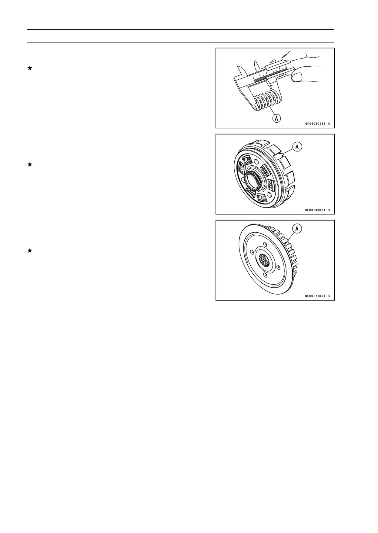
6-10 CLUTCH
Clutch
Clutch Spring Free Length Inspection
• Measure the free length of the clutch springs [A].
If any spring is shorter than the service limit, it must be
replaced.
Clutch Spring Free Length
Standard:
39.4 mm (1.55 in.)
Service Limit:
37.6 mm (1.48 in.)
Clutch Housing Finger Damage Inspection
• Visually inspect the clutch housing fingers [A] that come
in contact with the friction plate tangs.
If they are damaged or if there are groove cuts in the areas
that come in contact with the tangs, replace the housing.
Replace the friction plates if their tangs are damaged as
well.
Clutch Hub Spline Damage Inspection
• Visually inspect the areas of the clutch hub splines that
come in contact with the teeth of the steel plates.
If there are notches worn into the clutch hub splines [A],
replace the clutch hub. Replace the steel plates if their
teeth are damaged as well.
ENGINE LUBRICATION SYSTEM 7-1
Engine Lubrication System
Table of Contents
Exploded View
7-2
Specifications
7-4
Special Tools and Sealant
7-5
Engine Oil Flow Chart
7-6
Engine Oil and Oil Filter
7-7
Oil Level Inspection
7-7
Engine Oil Change
7-7
Oil Filter Replacement
7-7
Bypass Valve Disassembly
7-8
Bypass Valve Assembly
7-8
Bypass Valve Cleaning and Inspection
7-8
Oil Screen Cleaning and Inspection
7-9
7
Oil Pressure Relief Valve
7-10
Oil Pressure Relief Valve Removal
7-10
Oil Pressure Relief Valve Installation
7-10
Oil Pressure Relief Valve Inspection
7-10
Oil Pump
7-11
Oil Pump Removal
7-11
Oil Pump Installation
7-11
Oil Pump Disassembly
7-11
Oil Pump Assembly
7-11
Oil Pump Inspection
7-11
Oil Pressure Measurement
7-12
Oil Pressure Measurement
7-12
Oil Pressure Switch
7-13
Oil Pressure Switch Removal
7-13
Oil Pressure Switch Installation
7-13
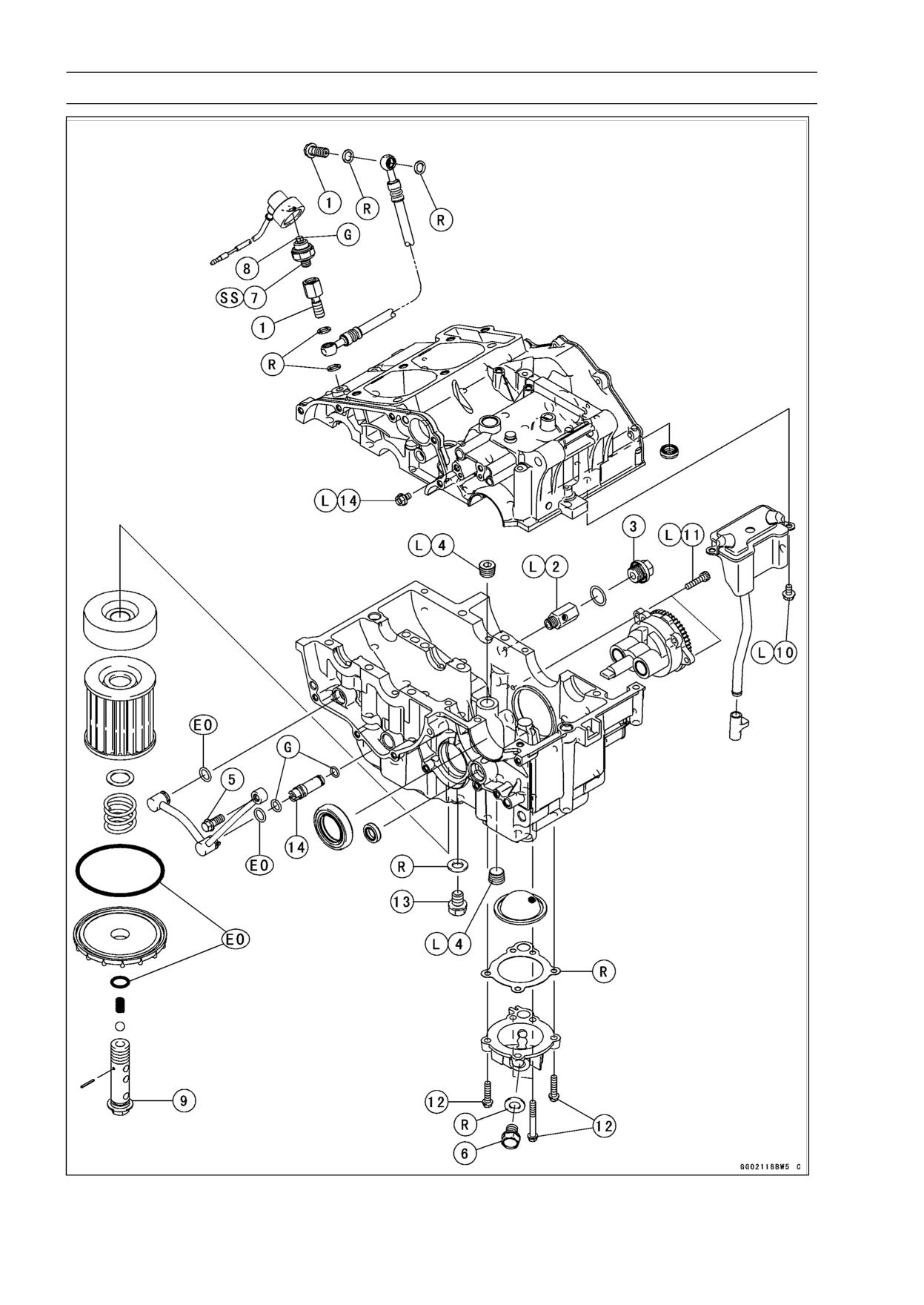
7-2 ENGINE LUBRICATION SYSTEM
Exploded View
ENGINE LUBRICATION SYSTEM 7-3
Exploded View
Torque
No.
Fastener
Remarks
N·m
kgf·m
ft·lb
1
Oil Hose Banjo Bolts
19.6
2.0
14.5
2
Oil Pressure Relief Valve
15
1.5
11
L
3
Crankcase Oil Passage Plug
15
1.5
11
4
Oil Passage Plugs for Oil Pump
20
2.0
15
L
5
Oil Pipe Banjo Bolt
12
1.2
104 in·lb
6
Oil Drain Bolt
19.6
2.0
14.5
7
Oil Pressure Switch
15
1.5
11
SS
8
Oil Pressure Switch Terminal Bolt
1.5
0.15
13 in·lb
G
9
Oil Filter Mounting Bolt
19.6
2.0
14.5
10
Oil Breather Mounting Bolts
9.8
1.0
87 in·lb
L
11
Oil Pump Mounting Bolts
9.8
1.0
87 in·lb
L
12
Oil Screen Cover Bolts
9.8
1.0
87 in·lb
13
Plug
19.6
2.0
14.5
14
Breather Bolt
9.8
1.0
87 in·lb
EO: Apply engine oil.
G: Apply grease.
L: Apply a non-permanent locking agent.
R: Replacement Parts
SS: Apply silicone sealant.
7-4 ENGINE LUBRICATION SYSTEM
Specifications
Item
Standard
Engine Oil
Type
API SG, SH, SJ, SL or SM with JASO MA, MA1 or MA2
Viscosity
SAE 10W-40
Capacity
1.3 L (1.37 US qt) (when filter is not removed)
1.6 L (1.69 US qt) (when filter is removed)
1.7 L (1.80 US qt) (when engine is completely dry)
Oil Pressure Measurement
Oil Pressure @4 000 r/min (rpm), Oil
98 ∼ 147 kPa (1.0 ∼ 1.5 kgf/cm², 14 ∼ 21 psi)
Temperature 90°C (194°F)
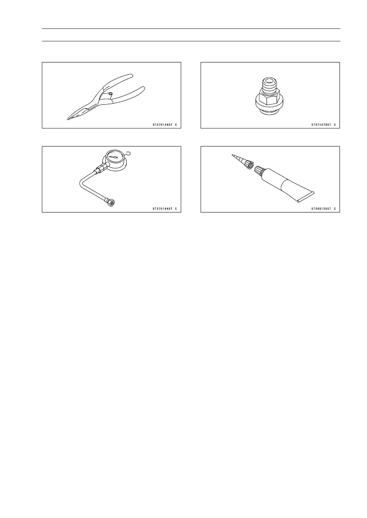
ENGINE LUBRICATION SYSTEM 7-5
Special Tools and Sealant
Outside Circlip Pliers:
Oil Pressure Gauge Adapter, M18 × 1.5:
57001-144
57001-1278
Oil Pressure Gauge, 10 kgf/cm²:
Liquid Gasket, TB1211:
57001-164
56019-120
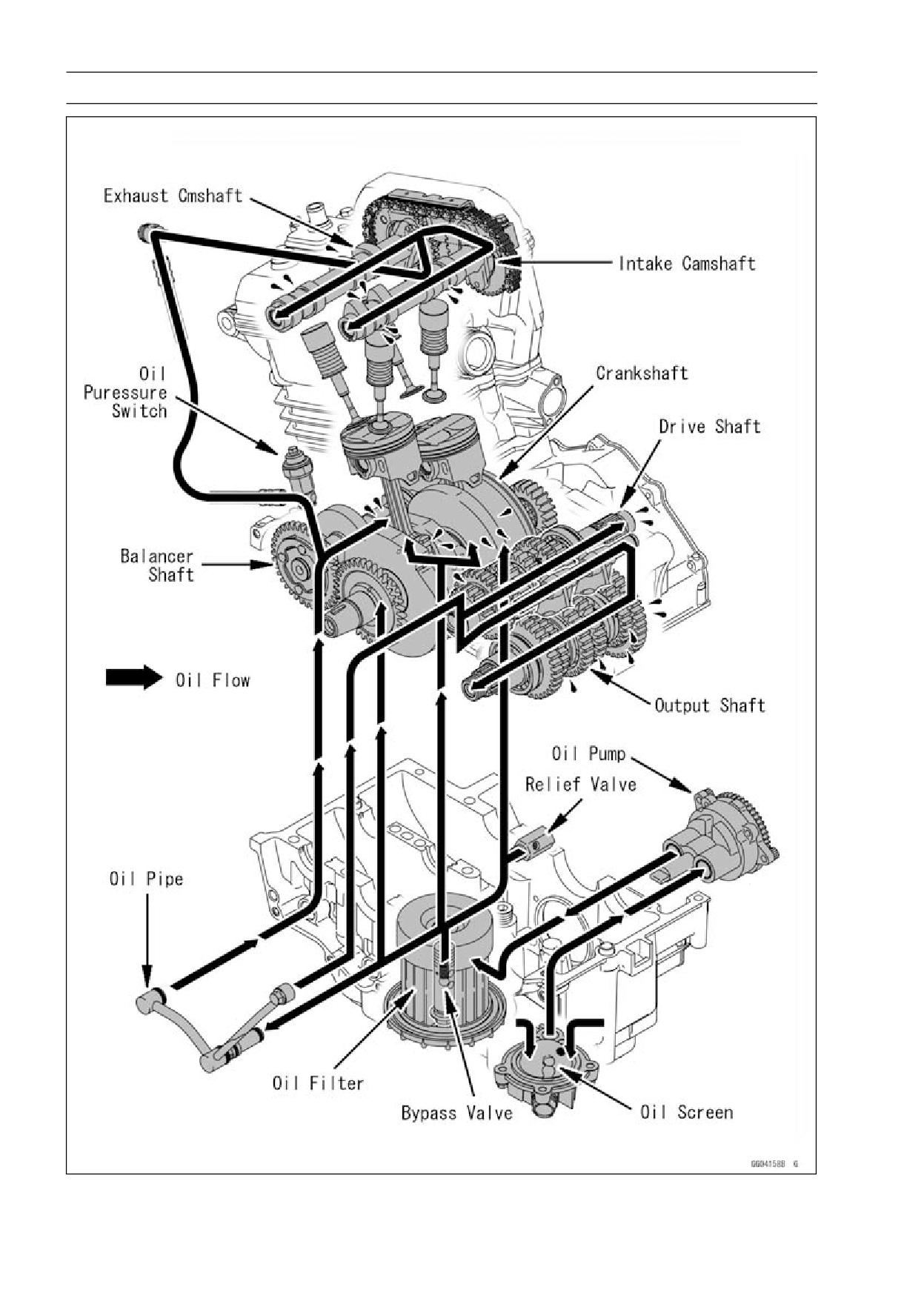
7-6 ENGINE LUBRICATION SYSTEM
Engine Oil Flow Chart
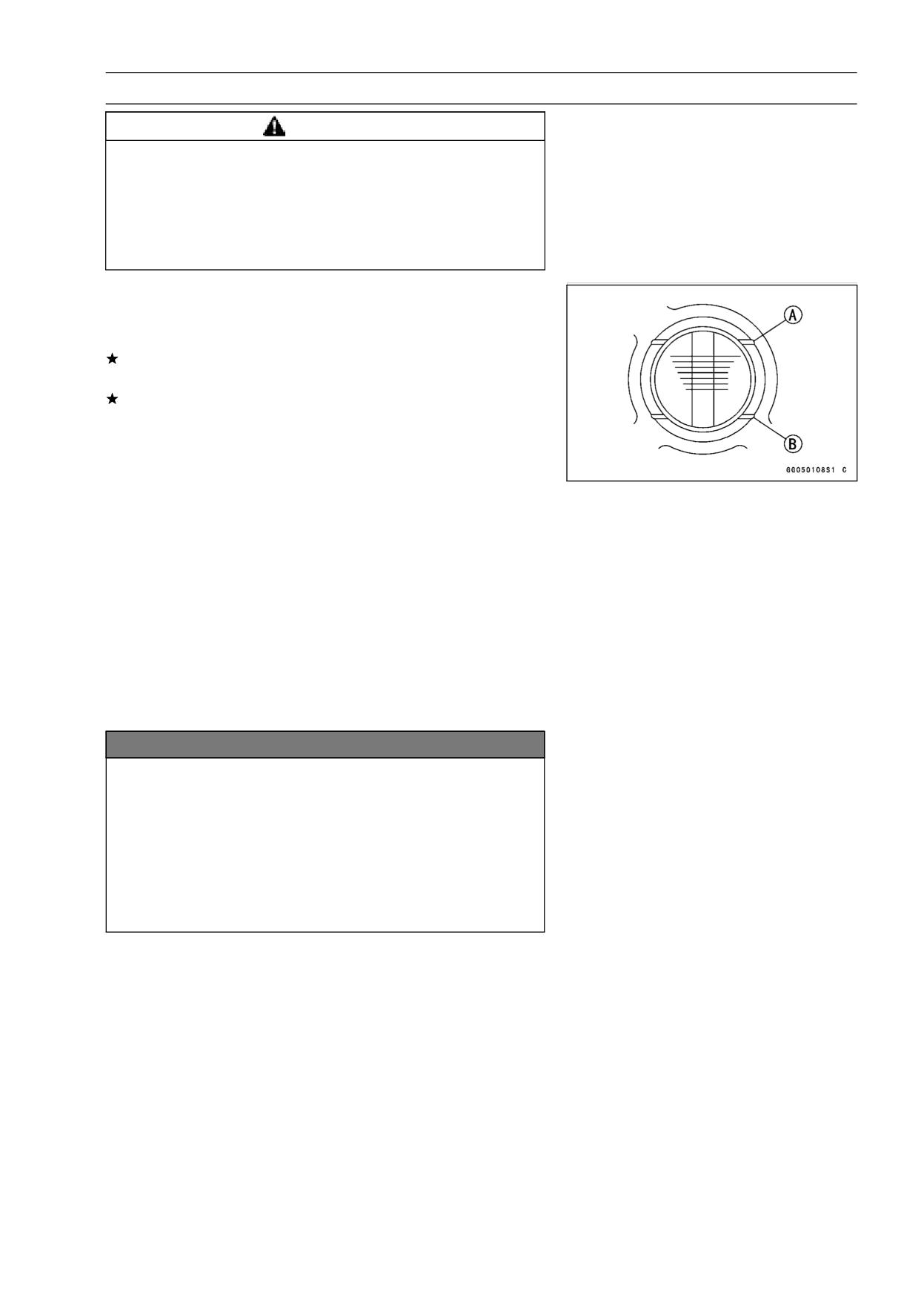
ENGINE LUBRICATION SYSTEM 7-7
Engine Oil and Oil Filter
WARNING
Vehicle operation with insufficient, deteriorated,
or contaminated engine oil will cause accelerated
wear and may result in engine seizure, accident,
and injury. Check the oil level before each use and
change the oil and filter according to the periodic
maintenance chart.
Oil Level Inspection
• Check that the engine oil level is between the upper [A]
and lower [B] levels in the gauge.
If the oil level is too high, remove the excess oil, using a
syringe or some other suitable device.
If the oil level is too low, add the correct amount of oil
through the oil filler opening. Use the same type and
make of oil that is already in the engine.
NOTE
○Situate the motorcycle so that it is perpendicular to the
ground.
○If the motorcycle has just been used, wait several min-
utes for all the oil to drain down.
○If the oil has just been changed, start the engine and
run it for several minutes at idle speed. This fills the oil
filter with oil. Stop the engine, then wait several minutes
until the oil settles.
○If the engine oil type and make are unknown, use any
brand of the specified oil to top up the level in preference
to running the engine with the oil level low. Then at your
earliest convenience, change the oil completely.
NOTICE
Racing the engine before the oil reaches every part
can cause engine seizure.
If the engine oil gets extremely low or if the oil pump
or oil passages clog up or otherwise do not function
properly, the oil pressure warning light will light. If
this light stays on when the engine is running above
idle speed, stop the engine immediately and find the
cause.
Engine Oil Change
• Refer to Engine Oil Change in the Periodic Maintenance
chapter (see Engine Oil Change in the Periodic Mainte-
nance chapter).
Oil Filter Replacement
• Refer to Oil Filter Replacement in the Periodic Mainte-
nance chapter (see Oil Filter Replacement in the Periodic
Maintenance chapter).
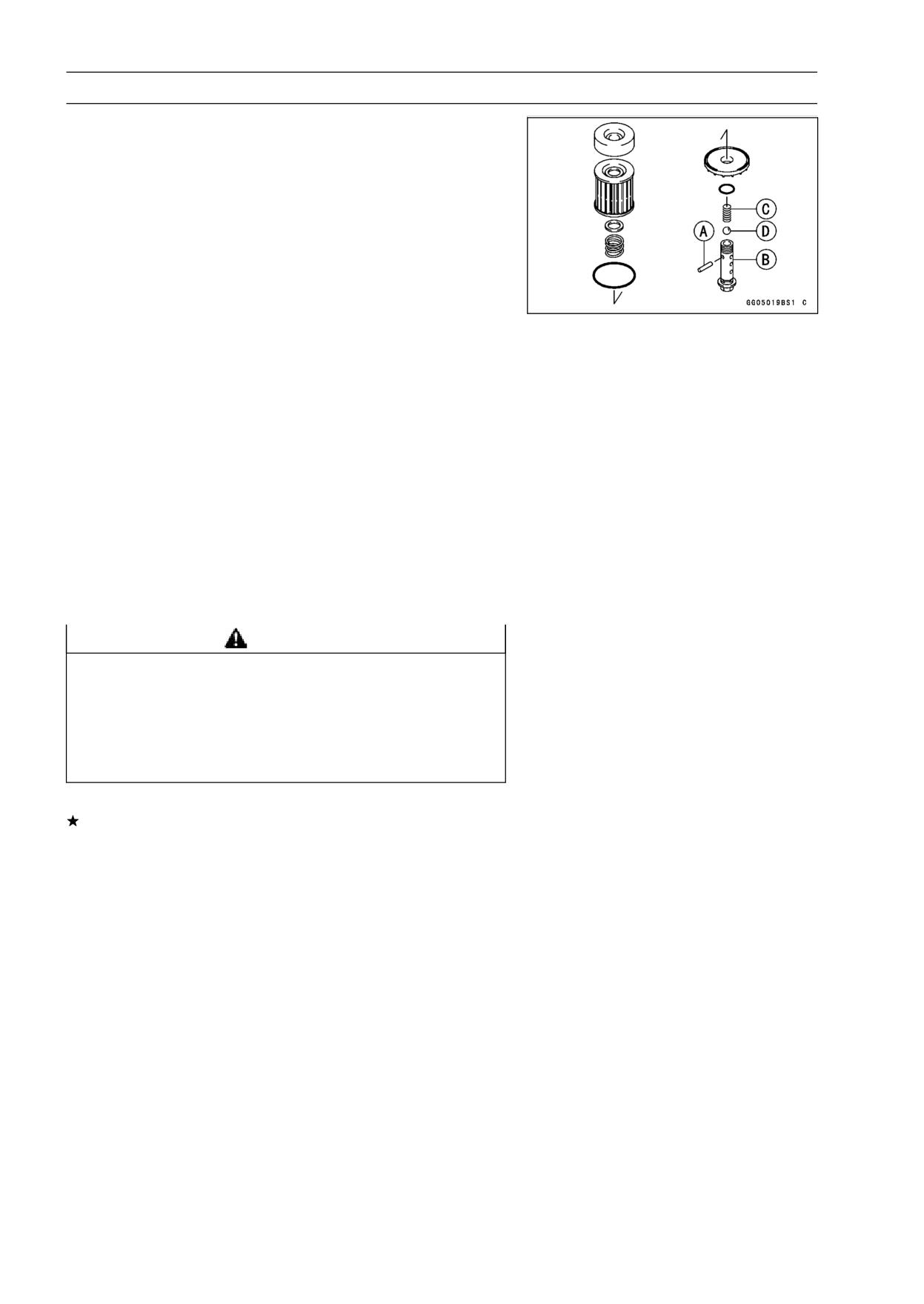
7-8 ENGINE LUBRICATION SYSTEM
Engine Oil and Oil Filter
Bypass Valve Disassembly
• Remove the oil filter (see Oil Filter Replacement in the
Periodic Maintenance chapter).
NOTE
○Oil draining is not necessary, but place the oil pan un-
der the oil filter because oil drain a little at the oil filter
removal.
• Drive the retaining pin [A] out of the filter mounting bolt
[B].
• Drop out the spring [C] and the bypass valve steel ball [D].
Bypass Valve Assembly
• Drop the bypass valve steel ball into the filter mounting
bolt.
• Put the spring into the mounting bolt and compress it be-
yond the small hole.
• Drive the retaining pin into the small hole to hold the
spring.
• Install the oil filter (see Oil Filter Replacement in the Pe-
riodic Maintenance chapter).
Bypass Valve Cleaning and Inspection
• Disassemble the bypass valve (see Bypass Valve Disas-
sembly).
• Clean the bypass valve parts in a high-flash point solvent.
WARNING
Gasoline and low-flash point solvents can be
flammable and/or explosive and cause severe
burns. Clean the parts in a well ventilated area, and
take care that there is no spark or flame anywhere
near the working areas. Do not use gasoline or
low-flash point solvents to clean parts.
• Visually inspect the bypass valve parts.
If there is any damaged part, replace it.
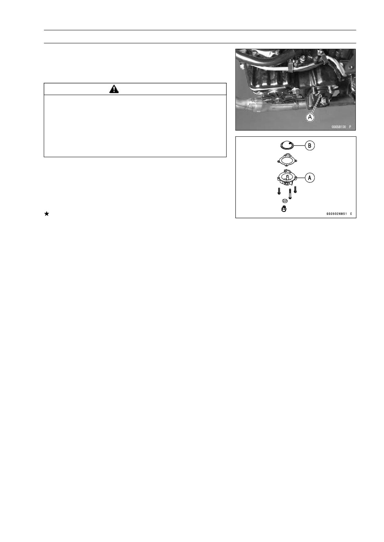
ENGINE LUBRICATION SYSTEM 7-9
Engine Oil and Oil Filter
Oil Screen Cleaning and Inspection
• Remove the oil screen cover [A].
• Clean the oil screen [B] with high-flash point solvent and
remove any particles stuck to it.
WARNING
Gasoline and low-flash point solvents can be
flammable and/or explosive and cause severe
burns. Clean the screen in a well-ventilated area,
and take care that there are no sparks or flame
anywhere near the working area; this includes any
appliance with a pilot light. Do not use gasoline or
a low-flash point solvent to clean the screen.
NOTE
○While cleaning the screen, check for any metal particles
that might indicate internal engine damage.
• Check the screen carefully for any damage: holes and
broken wires.
If the screen is damaged, replace the oil screen.
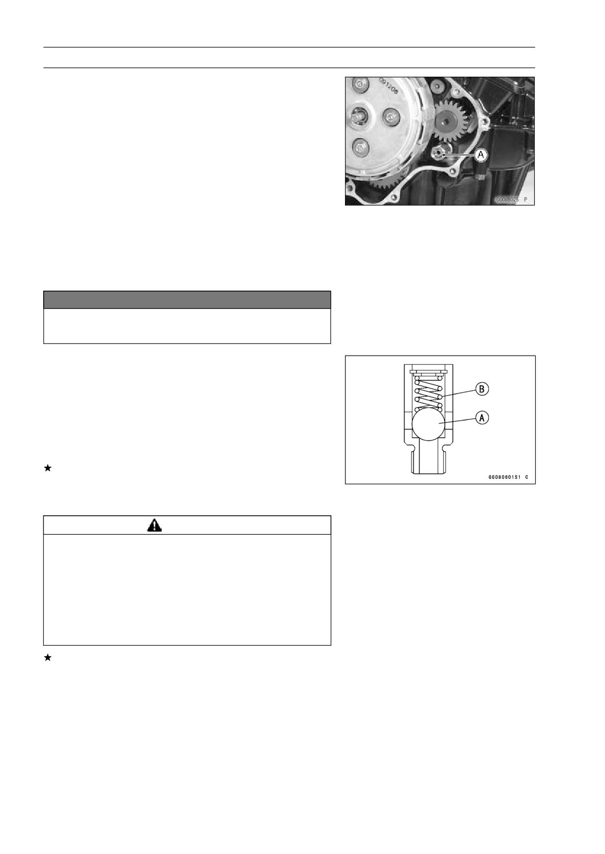
7-10 ENGINE LUBRICATION SYSTEM
Oil Pressure Relief Valve
Oil Pressure Relief Valve Removal
• Remove the clutch cover (see Clutch Cover Removal in
the Clutch chapter).
• Unscrew the oil pressure relief valve [A] from the
crankcase.
Oil Pressure Relief Valve Installation
• Apply a non-permanent locking agent to the threads of
the relief valve, and tighten it with the specified torque.
Torque - Oil Pressure Relief Valve: 15 N·m (1.5 kgf·m, 11
ft·lb)
NOTICE
Do not over apply a non-permanent locking agent
to the threads. This may block the oil passage.
Oil Pressure Relief Valve Inspection
• Check to see if the valve [A] slides smoothly when push-
ing it in with a wooden or other soft rod, and see if it comes
back to its seat by spring [B] pressure.
NOTE
○Inspect the valve in its assembled state. Disassembly
and assembly may change the valve performance.
If any rough spots are found during above inspection,
wash the valve clean with a high-flash point solvent and
blow out any foreign particles that may be in the valve with
compressed air.
WARNING
Gasoline and low-flash point solvents can be
flammable and/or explosive and cause severe
burns. Clean the oil pressure relief valve in a
well-ventilated area, and take care that there are no
sparks or flame anywhere near the working area;
this includes any appliance with a pilot light. Do
not use gasoline or a low-flash point solvent to
clean the oil pressure relief valve.
If cleaning does not solve the problem, replace the oil
pressure relief valve as an assembly. The oil pressure
relief valve is precision made with no allowance for re-
placement of individual parts.
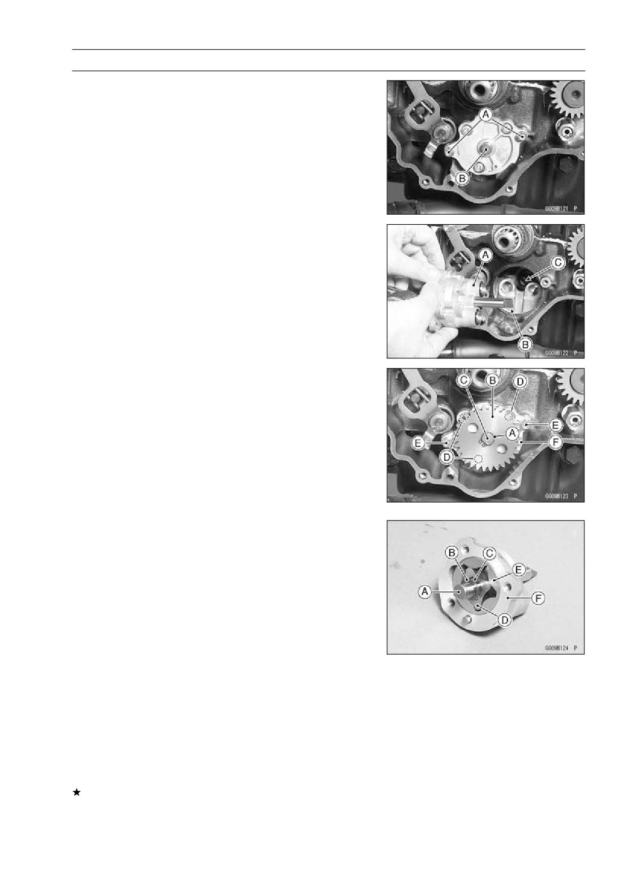
ENGINE LUBRICATION SYSTEM 7-11
Oil Pump
Oil Pump Removal
• Remove the clutch cover (see Clutch Cover Removal in
the Clutch chapter).
• Remove the clutch (see Clutch Removal in the Clutch
chapter).
• Remove the circlip and oil pump gear.
• Remove the oil pump mounting Allen bolts [A].
• Pull the oil pump [B] off the crankcase.
Oil Pump Installation
• Fill the oil pump with engine oil for initial lubrication.
• When installing the oil pump [A], note the position of the
water pump shaft slot [C] and turn the oil pump shaft so
that the projection [B] fits into the slot.
• Apply a non-permanent locking agent to the threads of the
oil pump mounting Allen bolts, and tighten them securely.
Torque - Oil Pump Mounting Bolts: 9.8 N·m (1.0 kgf·m, 87
in·lb)
Oil Pump Disassembly
• Remove the circlip [A] with circlip plire on the oil pump
shaft end.
Special Tool - Outside Circlip Pliers: 57001-144
• Take off the gear [B] from the shaft [C].
• Loosen the screws [D] before removing the oil pump
mounting bolts [E].
• Remove the oil pump (see Oil Pump Removal).
• Unscrew the oil pump cover screws [D] and take off the
cover [F].
• Pull the oil pump shaft [A], washer [B], pins [C], inner rotor
[D] and outer rotor [E] from the pump body [F].
Oil Pump Assembly
• Oil pump assembly is the reverse of disassembly.
• After completing the oil pump assembly, check that the
rotor shaft and rotor turn smoothly.
Oil Pump Inspection
• Disassemble the oil pump (see Oil Pump Disassembly).
• Visually inspect the oil pump body, inner and outer rotors
and covers.
If there is any damage or uneven wear, replace the oil
pump as an assembly.
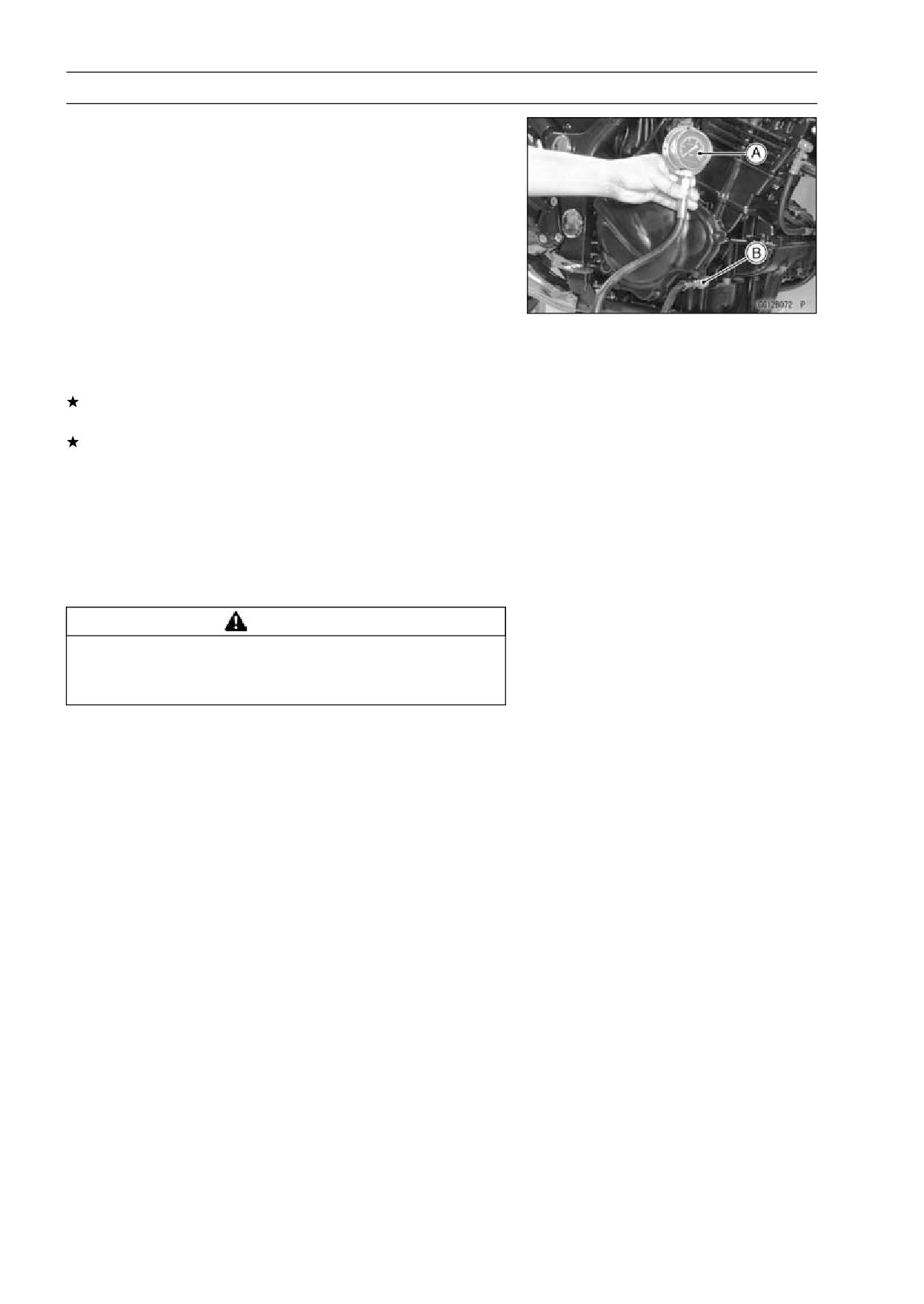
7-12 ENGINE LUBRICATION SYSTEM
Oil Pressure Measurement
Oil Pressure Measurement
• Remove the right lower fairing (see Lower Fairing Re-
moval in the Frame chapter).
• Remove the oil passage plug, and attach the adapter [B]
and gauge [A] to the plug hole.
Special Tools - Oil Pressure Gauge, 10 kgf/cm²: 57001-164
Oil Pressure Gauge Adapter, M18 × 1.5:
57001-1278
• Start the engine and warm up the engine.
• Run the engine at the specified speed, and read the oil
pressure gauge.
If the oil pressure is much lower than the standard, check
the oil pump and oil pump relief valve.
If the reading is much higher than the standard, check the
oil passages for clogging.
Oil Pressure
Standard:
98 ∼ 147 kPa (1.0 ∼ 1.5 kgf/cm², 14 ∼ 21 psi)
@ 4 000 r/min (rpm), oil temperature 90°C
(194°F)
• Stop the engine.
• Remove the oil pressure gauge and adapter.
WARNING
Hot oil can cause severe burns. Beware of hot en-
gine oil that will drain through the oil passage when
the gauge adapter is removed.
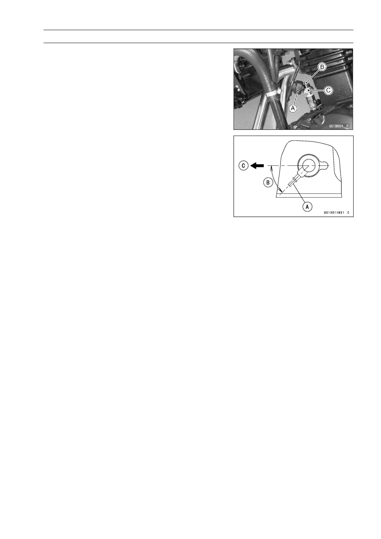
ENGINE LUBRICATION SYSTEM 7-13
Oil Pressure Switch
Oil Pressure Switch Removal
• Remove:
Left Lower Fairing (see Lower Fairing Removal in the
Frame chapter)
Switch Cover [A]
Switch Terminal Bolt [B]
Oil Pressure Switch [C]
Oil Pressure Switch Installation
• Apply liquid gasket to the threads of the oil pressure
switch and tighten it.
Sealant - Liquid Gasket, TB1211: 56019-120
Torque - Oil Pressure Switch: 15 N·m (1.5 kgf·m, 11 ft·lb)
• Tighten the oil pressure switch terminal bolt.
Torque - Oil Pressure Switch Terminal Bolt: 1.5 N·m (0.15
kgf·m, 13 in·lb)
○Install the oil pressure switch lead [A] as shown.
45° [B]
Front [C]
• Apply grease to the terminal.
ENGINE REMOVAL/INSTALLATION 8-1
Engine Removal/Installation
Table of Contents
Exploded View
8-2
Engine Removal/Installation
8-4
Engine Removal
8-4
Engine Installation
8-6
8
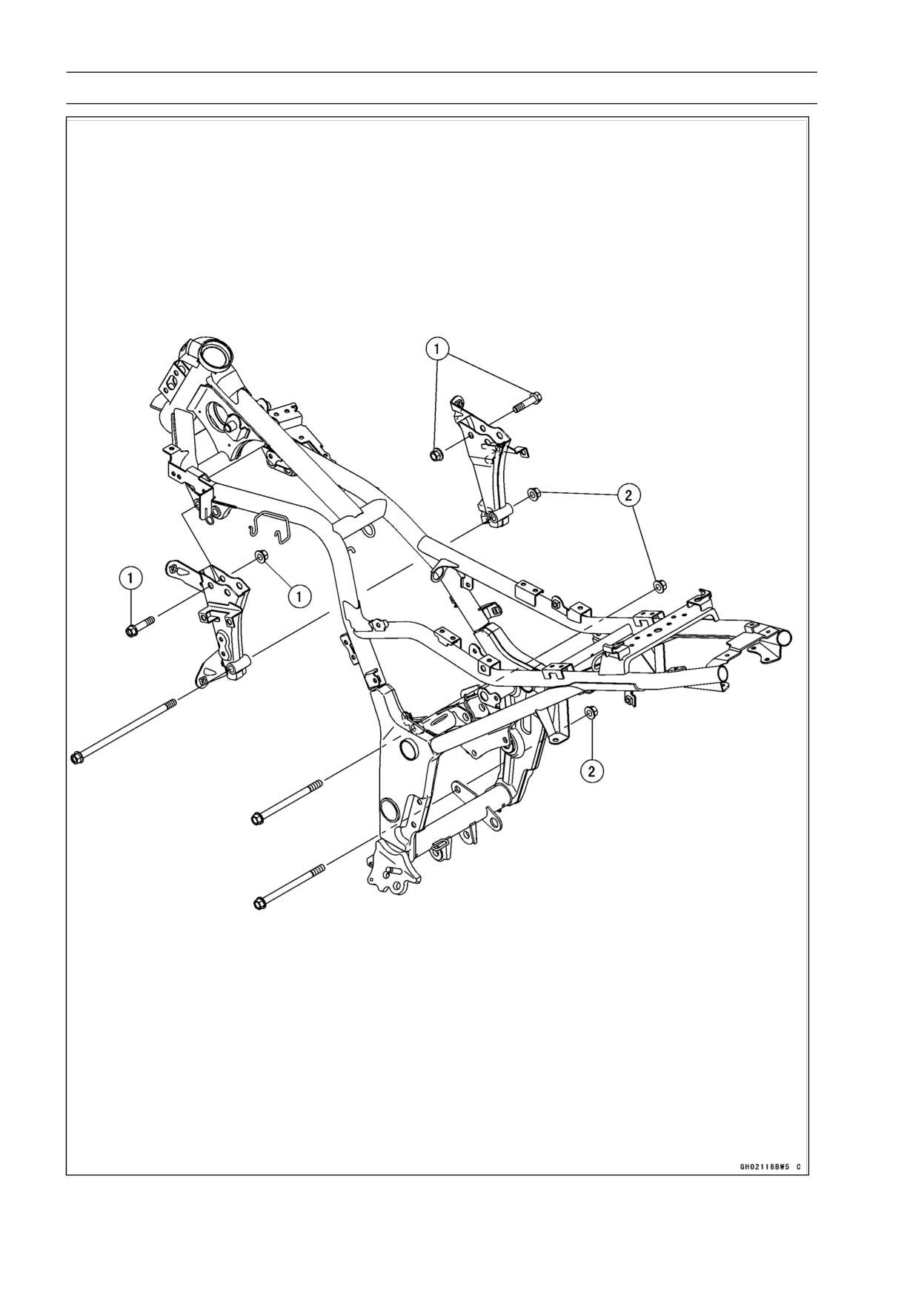
8-2 ENGINE REMOVAL/INSTALLATION
Exploded View
ENGINE REMOVAL/INSTALLATION 8-3
Exploded View
Torque
No.
Fastener
Remarks
N·m
kgf·m
ft·lb
1
Engine Mounting Bracket Bolts and Nuts
69
7.0
51
2
Engine Mounting Nuts
69
7.0
51
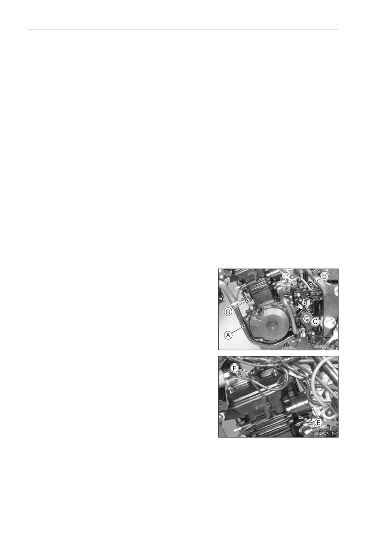
8-4 ENGINE REMOVAL/INSTALLATION
Engine Removal/Installation
Engine Removal
• Drain the engine oil (see Engine Oil Change in the Peri-
odic Maintenance chapter).
• Drain the coolant (see Coolant Change in the Periodic
Maintenance chapter).
• Remove:
Front Seat (see Front Seat Removal in the Frame chap-
ter)
Side Covers (see Side Cover Removal in the Frame
chapter)
Lower Fairings (see Lower Fairing Removal in the Frame
chapter)
Upper Fairings (see Upper Fairing Removal in the Frame
chapter)
Fuel Tank (see Fuel Tank Removal in the Fuel System
chapter)
Throttle Cable (see Throttle Cable Removal in the Fuel
System chapter)
Choke Cable (see Choke Cable Removal in the Fuel
System chapter)
Clutch Cable Lower End (see Clutch Cable Removal in
the Clutch chapter)
Muffler (see Muffler Removal in the Engine Top End
chapter)
Engine Sprocket (see Drive Chain Removal in the Final
Drive chapter)
• Remove:
Left Side Coolant Pipe [A]
Oil Pressure Switch Lead Connector [B]
Neutral Switch Terminal [C]
Breather Hose [D] at Air Cleaner Housing
Carburetor Holder Clamp (Loosen) [E]
Spark Plug Caps [F]
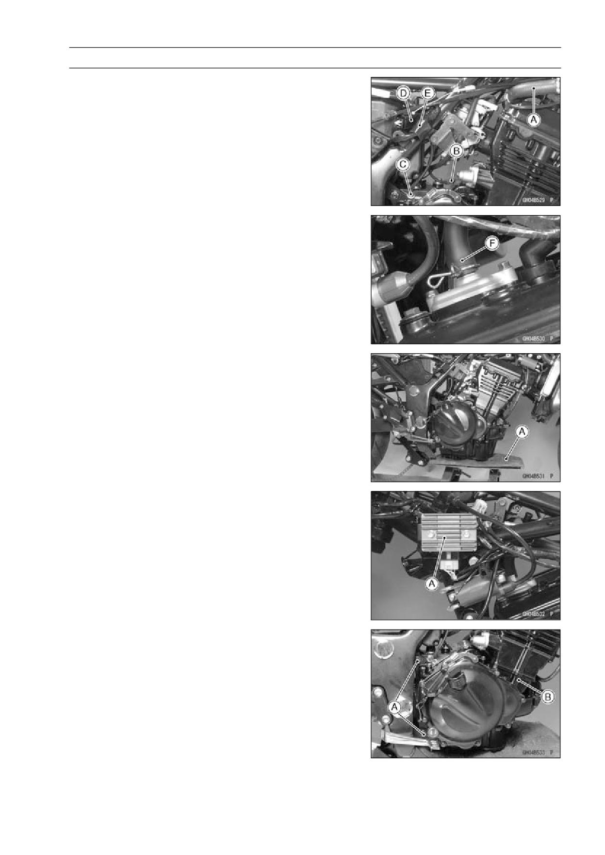
ENGINE REMOVAL/INSTALLATION 8-5
Engine Removal/Installation
• Remove or disconnect:
Cooling Hose [A] at Cylinder Head
Starter Motor Cable [B]
Engine Ground Terminal [C]
Alternator Lead Connector [D]
Crankshaft Sensor Lead Connector [E]
Air Suction Hose [F]
• Support the engine with a suitable stand [A].
• Remove the regulator/rectifier [A] and the engine mount-
ing bracket bolts and nuts.
• Remove:
Engine Mounting Bolts and Nuts [A]
Engine Assembly [B]
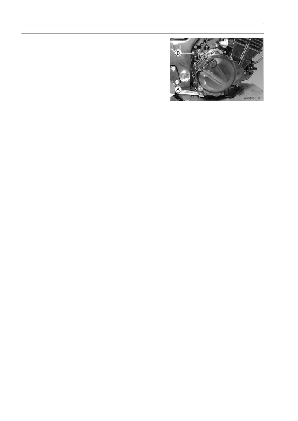
8-6 ENGINE REMOVAL/INSTALLATION
Engine Removal/Installation
Engine Installation
• Engine installation is the reverse of removal, and note the
following point.
○Insert the lower engine mounting bolt [A] first while sup-
porting the engine. Then insert the upper engine mount-
ing bolt [B], and tighten the nut loosely.
○Before tightening the mounting bolts, install the engine
brackets. When inserting the front engine mounting bolt,
use the suitable stand under the engine to lift it.
Torque - Engine Mounting Bracket Bolts, Nuts: 64 N·m (6.5
kgf·m, 47 ft·lb)
Engine Mounting Nuts: 64 N·m (6.5 kgf·m, 47 ft·lb)
○Run the wiring harness correctly (see Cable, Wire and
Hose Routing in the Appendix chapter).
○Adjust the following items after engine installation.
Throttle Cables (see Throttle Control System Inspection
in the Periodic Maintenance chapter)
Choke Cable (see Choke Cable Free Play Inspection in
the Fuel System chapter)
Clutch Cable (see Clutch Operation Inspection in the Pe-
riodic Maintenance chapter)
Drive Chain (see Drive Chain Slack Inspection in the
Periodic Maintenance chapter)
Carburetor Idling (see Idle Speed Inspection in the Peri-
odic Maintenance chapter)
• Fill the engine oil (see Engine Oil Change in the Periodic
Maintenance chapter).
• Fill the coolant (see Coolant Change in the Periodic Main-
tenance chapter).
CRANKSHAFT/TRANSMISSION 9-1
Crankshaft/Transmission
Table of Contents
Exploded View
9-2
Balancer
9-22
Specifications
9-6
Balancer Removal
9-22
Special Tools and Sealants
9-9
Balancer Installation
9-22
Crankcase
9-10
Balancer Shaft Bearing
Crankcase Splitting
9-10
Insert/Journal Wear Inspection .
9-22
Crankcase Assembly
9-11
Transmission
9-24
Crankcase Exchange
9-13
Shift Pedal Removal
9-24
Crankshaft and Connecting Rods
9-14
Shift Pedal Installation
9-24
Crankshaft Removal
9-14
External Shift Mechanism
Crankshaft Installation
9-14
Removal
9-25
Connecting Rod Removal
9-14
External Shift Mechanism
Connecting Rod Installation
9-15
Installation
9-25
Crankshaft/Connecting Rod
External Shift Mechanism
Cleaning
9-15
Inspection
9-26
Connecting Rod Bend Inspection
9-16
Transmission Removal
9-27
Connecting Rod Twist Inspection.
9-16
Transmission Installation
9-27
Connecting Rod Big End Side
Transmission Shaft Disassembly.
9-27
9
Clearance Inspection
9-16
Transmission Shaft Assembly
9-28
Connecting Rod Big End
Shift Drum and Fork Removal
9-29
Bearing Insert/Crankpin Wear
Shift Drum and Fork Installation...
9-30
Inspection
9-17
Shift Drum Disassembly
9-30
Crankshaft Side Clearance
Shift Drum Assembly
9-30
Inspection
9-18
Gear Backlash Inspection
9-31
Crankshaft Runout Inspection
9-19
Shift Fork Bending Inspection
9-31
Crankshaft Main Bearing
Shift Fork/Gear Groove Wear
Insert/Journal Wear Inspection .
9-19
Inspection
9-31
Starter Motor Clutch
9-21
Shift Fork Guide Pin/Drum
Starter Motor Clutch
Groove Wear Inspection
9-31
Removal/Installation
9-21
Gear Dog and Gear Dog Hole
Starter Motor Clutch Inspection ...
9-21
Damage Inspection
9-32
Starter Motor Clutch Disassembly
9-21
Ball and Needle Bearing Wear
Starter Motor Clutch Assembly
9-21
Inspection
9-32
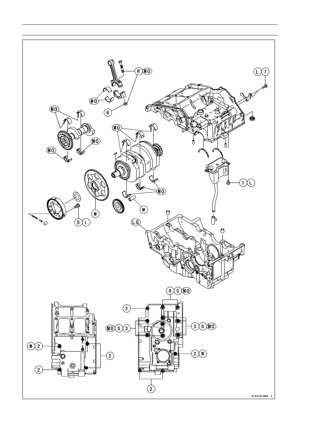
9-2 CRANKSHAFT/TRANSMISSION
Exploded View
CRANKSHAFT/TRANSMISSION 9-3
Exploded View
Torque
No.
Fastener
Remarks
N·m
kgf·m
ft·lb
1
Oil Breather Mounting Bolts
9.8
1.0
87 in·lb
L
2
Crankcase Bolts
6
12
1.2
104 in·lb
3
Crankcase Bolts
8 (L = 90)
24
2.4
18
MO, S
4
Crankcase Bolts
8 (L = 73)
19
1.9
14
MO, S
5
Starter Motor Clutch Bolts
34.3
3.5
25
L
6
Connecting Rod Big End Cap Nuts
27.5
2.8
20
MO
7
Shift Drum Bearing Holder Bolt
12
1.2
104 in·lb
L
L: Apply a non-permanent locking agent.
LG: Apply liquid gasket.
M: Apply molybdenum disulfide grease.
MO: Apply molybdenum disulfide oil solution (mixture of the engine oil and molybdenum disulfide
grease in a weight ratio 10:1).
R: Replacement Parts
S: Follow the specified tightening sequence.
W: Washer
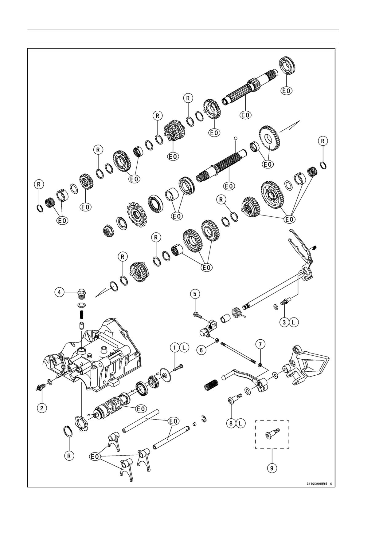
9-4 CRANKSHAFT/TRANSMISSION
Exploded View
CRANKSHAFT/TRANSMISSION 9-5
Exploded View
Torque
No.
Fastener
Remarks
N·m
kgf·m
ft·lb
1
Shift Drum Pin Plate Bolt
9.0
0.9
80 in·lb
L
2
Neutral Switch
15
1.5
11
3
External Shift Mechanism Return Spring Pin
19.6
2.0
14.5
L
4
Shift Drum Positioning Bolt
24.5
2.5
18
5
Shift Lever Link Bolt
12
1.2
104 in·lb
6
Front Tie-Rod Locknut (Left-Hand Threads)
7.0
0.7
62 in·lb
7
Rear Tie-Rod Locknut (Right-Hand Threads)
7.0
0.7
62 in·lb
EX250J8 ∼ JB (with a non-permanent locking
8
agent)
20
2.0
15
L
Shift Pedal Mounting Bolt
EX250JB ∼ JC (with a non-permanent locking
9
agent)
25
2.5
18
Shift Pedal Mounting Bolt
EO: Apply engine oil.
G: Apply grease.
L: Apply a non-permanent locking agent.
R: Replacement Parts
9-6 CRANKSHAFT/TRANSMISSION
Specifications
Item
Standard
Service Limit
Crankshaft, Connecting Rods
Connecting Rod Bend
---
TIR 0.2/100 mm
(0.008/3.94 in.)
Connecting Rod Twist
---
TIR 0.2/100 mm
(0.008/3.94 in.)
Connecting Rod Big End Side Clearance
0.13 ∼ 0.38 mm
0.58 mm
(0.005 ∼ 0.015 in.)
(0.023 in.)
Connecting Rod Big End Bearing
0.031 ∼ 0.059 mm
0.10 mm
Insert/Crankpin Clearance
(0.0012 ∼ 0.0023 in.)
(0.004 in.)
Crankpin Diameter:
29.984 ∼ 30.000 mm
29.97 mm
(1.1805 ∼ 1.1811 in.)
(1.18 in.)
Marking
None
29.984 ∼ 29.994 mm
- - -
(1.1805 ∼ 1.1809 in.)
○
29.995 ∼ 30.000 mm
- - -
(1.1809 ∼ 1.1811 in.)
Connecting Rod Big End Bore Diameter:
33.000 ∼ 33.016 mm
- - -
(1.2992 ∼ 1.2998 in.)
Marking
None
33.000 ∼ 33.008 mm
- - -
(1.2992 ∼ 1.2995 in.)
○
33.009 ∼ 33.016 mm
- - -
(1.2996 ∼ 1.2998 in.)
Connecting Rod Big End Bearing Insert
Thickness:
Brown
1.480 ∼ 1.485 mm
- - -
(0.0583 ∼ 0.0585 in.)
Black
1.485 ∼ 1.490 mm
- - -
(0.0585 ∼ 0.0587 in.)
Blue
1.489 ∼ 1.494 mm
- - -
(0.0586 ∼ 0.0588 in.)
Crankshaft Runout
TIR 0.02 mm (0.0008 in.) or
TIR 0.05 mm
less
(0.0020 in.)
Crankshaft Main Bearing Insert/Journal
0.014 ∼ 0.038 mm*
0.07 mm
Clearance
(0.0006 ∼ 0.0015 in.)
(0.0028 in.)
Crankshaft Main Journal Diameter:
27.984 ∼ 28.000 mm
27.96 mm
(1.1017 ∼ 1.1024 in.)
(1.101 in.)
Marking
None
27.984 ∼ 27.992 mm
- - -
(1.1017 ∼ 1.1020 in.)
1
27.993 ∼ 28.000 mm
- - -
(1.1021 ∼ 1.1024 in.)
Crankcase Main Bearing Bore Diameter:
31.000 ∼ 31.016 mm
- - -
(1.2205 ∼ 1.2211 in.)
Marking
○
31.000 ∼ 31.008 mm
- - -
(1.2205 ∼ 1.2208 in.)