Kawasaki Ninja 250R Motorcycle. Service Manual (2007) - page 1
LIST OF ABBREVIATIONS
A
ampere(s)
lb
pound(s)
ABDC
after bottom dead center
m
meter(s)
AC
alternating current
min
minute(s)
ATDC
after top dead center
N
newton(s)
BBDC
before bottom dead center
Pa
pascal(s)
BDC
bottom dead center
PS
horsepower
BTDC
before top dead center
psi
pound(s) per square inch
°C
degree(s) Celsius
r
revolution
DC
direct current
rpm
revolution(s) per minute
F
farad(s)
TDC
top dead center
°F
degree(s) Fahrenheit
TIR
total indicator reading
ft
foot, feet
V
volt(s)
g
gram(s)
W
watt(s)
h
hour(s)
Ω
ohm(s)
L
liter(s)
COUNTRY AND AREA CODES
AU
Australia
ID
Indonesia
CA
Canada
MY
Malaysia
CAL
California
PH
Philippines
CO
Colombia
US
United States
EMISSION CONTROL INFORMATION
To protect the environment in which we all live, Kawasaki has incorporated crankcase emis-
sion (1) and exhaust emission (2) control systems in compliance with applicable regulations of
the United States Environmental Protection Agency and California Air Resources Board. Addi-
tionally, Kawasaki has incorporated an evaporative emission control system (3) in compliance
with applicable regulations of the California Air Resources Board on vehicles sold in California
only.
1. Crankcase Emission Control System
This system eliminates the release of crankcase vapors into the atmosphere. Instead, the vapors
are routed through an oil separator to the inlet side of the engine. While the engine is operating,
the vapors are drawn into combustion chamber, where they are burned along with the fuel and air
supplied by the fuel injection system.
2. Exhaust Emission Control System
This system reduces the amount of pollutants discharged into the atmosphere by the exhaust
of this motorcycle. The fuel, ignition, and exhaust systems of this motorcycle have been carefully
designed and constructed to ensure an efficient engine with low exhaust pollutant levels.
The exhaust system of this model motorcycle manufactured primarily for sale in California in-
cludes a catalytic converter system.
3. Evaporative Emission Control System
Vapors caused by fuel evaporation in the fuel system are not vented into the atmosphere. In-
stead, fuel vapors are routed into the running engine to be burned, or stored in a canister when
the engine is stopped. Liquid fuel is caught by a vapor separator and returned to the fuel tank.
The Clean Air Act, which is the Federal law covering motor vehicle pollution, contains what is
commonly referred to as the Act’s “tampering provisions”.
“Sec. 203(a) The following acts and the causing thereof are prohibited...
(3)(A) for any person to remove or render inoperative any device or element of design installed
on or in a motor vehicle or motor vehicle engine in compliance with regulations under this
title prior to its sale and delivery to the ultimate purchaser, or for any manufacturer or dealer
knowingly to remove or render inoperative any such device or element of design after such
sale and delivery to the ultimate purchaser.
(3)(B) for any person engaged in the business of repairing, servicing, selling, leasing, or trading
motor vehicles or motor vehicle engines, or who operates a fleet of motor vehicles know-
ingly to remove or render inoperative any device or element of design installed on or in a
motor vehicle or motor vehicle engine in compliance with regulations under this title follow-
ing its sale and delivery to the ultimate purchaser...”
NOTE
○The phrase “remove or render inoperative any device or element of design” has been generally
interpreted as follows.
1. Tampering does not include the temporary removal or rendering inoperative of de-
vices or elements of design in order to perform maintenance.
2. Tampering could include.
a.Maladjustment of vehicle components such that the emission standards are ex-
ceeded.
b.Use of replacement parts or accessories which adversely affect the performance
or durability of the motorcycle.
c.Addition of components or accessories that result in the vehicle exceeding the stan-
dards.
d.Permanently removing, disconnecting, or rendering inoperative any component or
element of design of the emission control systems.
WE RECOMMEND THAT ALL DEALERS OBSERVE THESE PROVISIONS OF FEDERAL LAW,
THE VIOLATION OF WHICH IS PUNISHABLE BY CIVIL PENALTIES NOT EXCEEDING $10
000 PER VIOLATION.
TAMPERING WITH NOISE CONTROL SYSTEM PROHIBITED
Federal law prohibits the following acts or the causing thereof. (1) The removal or rendering
inoperative by any person other than for purposes of maintenance, repair, or replacement, of any
device or element of design incorporated into any new vehicle for the purpose of noise control
prior to its sale or delivery to the ultimate purchaser or while it is in use, or (2) the use of the
vehicle after such device or element of design has been removed or rendered inoperative by
any person.
Among those acts presumed to constitute tampering are the acts listed below.
• Replacement of the original exhaust system or muffler with a component not in compliance
with Federal regulations.
• Removal of the muffler(s) or any internal portion of the muffler(s).
• Removal of the air box or air box cover.
• Modifications to the muffler(s) or air inlet system by cutting, drilling, or other means if such
modifications result in increased noise levels.
Foreword
This manual is designed primarily for use by
The Quick Reference Guide shows you all
trained mechanics in a properly equipped shop.
of the product’s system and assists in locating
However, it contains enough detail and basic in-
their chapters. Each chapter in turn has its own
formation to make it useful to the owner who de-
comprehensive Table of Contents.
sires to perform his own basic maintenance and
For example, if you want ignition coil informa-
repair work. A basic knowledge of mechanics,
tion, use the Quick Reference Guide to locate
the proper use of tools, and workshop proce-
the Electrical System chapter. Then, use the
dures must be understood in order to carry out
Table of Contents on the first page of the chap-
maintenance and repair satisfactorily. When-
ter to find the ignition coil section.
ever the owner has insufficient experience or
Whenever you see symbols, heed their in-
doubts his ability to do the work, all adjust-
structions! Always follow safe operating and
ments, maintenance, and repair should be car-
maintenance practices.
ried out only by qualified mechanics.
DANGER
In order to perform the work efficiently and
DANGER indicates a hazardous situa-
to avoid costly mistakes, read the text, thor-
tion which, if not avoided, will result in
oughly familiarize yourself with the procedures
death or serious injury.
before starting work, and then do the work care-
fully in a clean area. Whenever special tools or
WARNING
equipment are specified, do not use makeshift
tools or equipment. Precision measurements
WARNING indicates a hazardous situa-
can only be made if the proper instruments are
tion which, if not avoided, could result
used, and the use of substitute tools may ad-
in death or serious injury.
versely affect safe operation.
For the duration of the warranty period,
NOTICE
we recommend that all repairs and scheduled
NOTICE is used to address practices not
maintenance be performed in accordance with
related to personal injury.
this service manual. Any owner maintenance or
repair procedure not performed in accordance
This manual contains four more symbols
with this manual may void the warranty.
which will help you distinguish different types
To get the longest life out of your vehicle:
of information.
• Follow the Periodic Maintenance Chart in the
Service Manual.
NOTE
○This note symbol indicates points of par-
• Be alert for problems and non-scheduled
maintenance.
ticular interest for more efficient and con-
venient operation.
• Use proper tools and genuine Kawasaki Mo-
torcycle parts. Special tools, gauges, and
testers that are necessary when servicing
• Indicates a procedural step or work to be
done.
Kawasaki motorcycles are introduced by the
○Indicates a procedural sub-step or how to do
Service Manual. Genuine parts provided as
the work of the procedural step it follows. It
spare parts are listed in the Parts Catalog.
also precedes the text of a NOTE.
• Follow the procedures in this manual care-
Indicates a conditional step or what action to
fully. Don’t take shortcuts.
take based on the results of the test or inspec-
• Remember to keep complete records of main-
tion in the procedural step or sub-step it fol-
tenance and repair with dates and any new
lows.
parts installed.
In most chapters an exploded view illustration
of the system components follows the Table of
How to Use This Manual
Contents. In these illustrations you will find the
In this manual, the product is divided into its
instructions indicating which parts require spec-
major systems and these systems make up the
ified tightening torque, oil, grease or a locking
manual’s chapters.
agent during assembly.
GENERAL INFORMATION 1-1
General Information
Table of Contents
1
Before Servicing
1-2
Model Identification
1-7
General Specifications
1-8
Unit Conversion Table
1-11
1-2 GENERAL INFORMATION
Before Servicing
Before starting to perform an inspection service or carry out a disassembly and reassembly opera-
tion on a motorcycle, read the precautions given below. To facilitate actual operations, notes, illustra-
tions, photographs, cautions, and detailed descriptions have been included in each chapter wherever
necessary. This section explains the items that require particular attention during the removal and
reinstallation or disassembly and reassembly of general parts.
Especially note the following.
Battery Ground
Before completing any service on the motorcycle, discon-
nect the battery cables from the battery to prevent the en-
gine from accidentally turning over. Disconnect the ground
cable (-) first and then the positive (+). When completed
with the service, first connect the positive (+) cable to the
positive (+) terminal of the battery then the negative (-) ca-
ble to the negative terminal.
Edges of Parts
Lift large or heavy parts wearing gloves to prevent injury
from possible sharp edges on the parts.
Solvent
Use a high-flush point solvent when cleaning parts. High
-flush point solvent should be used according to directions
of the solvent manufacturer.
Cleaning vehicle before disassembly
Clean the vehicle thoroughly before disassembly. Dirt or
other foreign materials entering into sealed areas during ve-
hicle disassembly can cause excessive wear and decrease
performance of the vehicle.
GENERAL INFORMATION 1-3
Before Servicing
Arrangement and Cleaning of Removed Parts
Disassembled parts are easy to confuse. Arrange the
parts according to the order the parts were disassembled
and clean the parts in order prior to assembly.
Storage of Removed Parts
After all the parts including subassembly parts have been
cleaned, store the parts in a clean area. Put a clean cloth
or plastic sheet over the parts to protect from any foreign
materials that may collect before re-assembly.
Inspection
Reuse of worn or damaged parts may lead to serious ac-
cident. Visually inspect removed parts for corrosion, discol-
oration, or other damage. Refer to the appropriate sections
of this manual for service limits on individual parts. Replace
the parts if any damage has been found or if the part is be-
yond its service limit.
Replacement Parts
Replacement Parts must be KAWASAKI genuine or
recommended by KAWASAKI. Gaskets, O-rings, oil seals,
grease seals, circlips, cotter pins or self-looking nuts must
be replaced with new ones whenever disassembled.
Assembly Order
In most cases assembly order is the reverse of disassem-
bly, however, if assembly order is provided in this Service
Manual, follow the procedures given.
1-4 GENERAL INFORMATION
Before Servicing
Tightening Sequence
Generally, when installing a part with several bolts, nuts,
or screws, start them all in their holes and tighten them to
a snug fit. Then tighten them according to the specified se-
quence to prevent case warpage or deformation which can
lead to malfunction. Conversely when loosening the bolts,
nuts, or screws, first loosen all of them by about a quar-
ter turn and then remove them. If the specified tightening
sequence is not indicated, tighten the fasteners alternating
diagonally.
Tightening Torque
Incorrect torque applied to a bolt, nut, or screw may
lead to serious damage. Tighten fasteners to the specified
torque using a good quality torque wrench.
Force
Use common sense during disassembly and assembly,
excessive force can cause expensive or hard to repair dam-
age. When necessary, remove screws that have a non
-permanent locking agent applied using an impact driver.
Use a plastic-faced mallet whenever tapping is necessary.
Gasket, O-ring
Hardening, shrinkage, or damage of both gaskets and
O-rings after disassembly can reduce sealing performance.
Remove the old gaskets and clean the sealing surfaces
thoroughly so that no gasket material or other material re-
mains. Install the new gaskets and replace the used O-rings
when re-assembling
Liquid Gasket, Non-permanent Locking Agent
For applications that require Liquid Gasket or a
Non-permanent Locking Agent, clean the surfaces so
that no oil residue remains before applying liquid gasket or
non-permanent locking agent. Do not apply them exces-
sively. Excessive application can clog oil passages and
cause serious damage.
GENERAL INFORMATION 1-5
Before Servicing
Press
For items such as bearings or oil seals that must be
pressed into place, apply small amount of oil to the con-
tact area. Be sure to maintain proper alignment and use
smooth movements when installing.
Ball Bearing and Needle Bearing
Do not remove pressed ball or needle unless removal is
absolutely necessary. Replace with new ones whenever
removed. Press bearings with the manufacturer and size
marks facing out. Press the bearing into place by putting
pressure on the correct bearing race as shown.
Pressing the incorrect race can cause pressure between
the inner and outer race and result in bearing damage.
Oil Seal, Grease Seal
Do not remove pressed oil or grease seals unless removal
is necessary. Replace with new ones whenever removed.
Press new oil seals with manufacture and size marks facing
out. Make sure the seal is aligned properly when installing.
Apply specified grease to the lip of seal before installing
the seal.
Circlips, Cotter Pins
Replace the circlips or cotter pins that were removed with
new ones. Take care not to open the clip excessively when
installing to prevent deformation.
1-6 GENERAL INFORMATION
Before Servicing
Lubrication
It is important to lubricate rotating or sliding parts during
assembly to minimize wear during initial operation. Lubri-
cation points are called out throughout this manual, apply
the specific oil or grease as specified.
Direction of Engine Rotation
When rotating the crankshaft by hand, the free play
amount of rotating direction will affect the adjustment. Ro-
tate the crankshaft to positive direction (clockwise viewed
from output side).
Electrical Wires
A two-color wire is identified first by the primary color and
then the stripe color. Unless instructed otherwise, electrical
wires must be connected to those of the same color.
Instrument
Use a meter that has enough accuracy for an accurate
measurement. Read the manufacture’s instructions thor-
oughly before using the meter. Incorrect values may lead
to improper adjustments.
GENERAL INFORMATION 1-7
Model Identification
EX250J8 Left Side View (United States and Canada)
EX250J8 Right Side View (United States and Canada)
Frame Number
Engine Number
1-8 GENERAL INFORMATION
General Specifications
Items
EX250J8 ∼ JC
Dimensions
Overall Length
2 085 mm (82.1 in.), (AU) 2 080 mm (81.9 in.)
Overall Width
715 mm (28.1 in.)
Overall Height
1 110 mm (43.7 in.), (AU) 1 115 mm (43.9 in.)
Wheelbase
1 400 mm (55.1 in.), (AU) 1 390 mm (54.7 in.)
Road Clearance
130 mm (5.1 in.), (AU, ID) 140 mm (5.5 in.)
Seat Height
775 mm (30.5 in.)
Dry Mass
EX250J8
152 kg (335 lb), (CAL) 153 kg (337 lb), (IN) 154 kg (340 lb)
Curb Mass:
EX250J9 ∼ JC
170 kg (375 lb), (AU) 169 kg (373 lb)
Front
82 kg (181 lb), (ID) 83 kg (183 lb)
Rear
88 kg (194 lb), (AU, ID) 87 kg (192 lb)
Fuel Tank Capacity
18 L (4.8 US gal.)
Performance
Minimum Turning Radius
2.7 m (8.9 ft)
Engine
Type
4-stroke, DOHC, 2-cylinder
Cooling System
Liquid-cooled
Bore and Stroke
62.0 × 41.2 mm (2.5 × 1.6 in.)
Displacement
249 cm³ (15.2 cu in.)
Compression Ratio
11.6
Maximum Horsepower
24 kW (32.6 PS) @11 000 r/min (rpm)
(ID) 23.4 kW (31.8 PS) @11 000 r/min (rpm)
Maximum Torque
22.0 N·m (2.24 kgf·m, 16.2 ft·lb) @9 500 r/min (rpm)
Carburetion System
Carburetor, Keihin CVK 30× 2
Starting System
Electric starter
Ignition System
Battery and coil (transistorized)
Timing Advance
Electronically advanced
Ignition Timing
From 10° BTDC @1 300 r/min (rpm) to
35° BTDC @4 000 r/min (rpm)
Spark Plug
NGK CR8E or ND U24ESR-N
Cylinder Numbering Method
Left to right, 1-2
Firing Order
1-2
Valve Timing:
Inlet:
Open
36° BTDC
Close
56° ABDC
Duration
272°
Exhaust:
Open
61° BBDC
Close
31° ATDC
Duration
272°
GENERAL INFORMATION 1-9
General Specifications
Items
EX250J8 ∼ JC
Lubrication System
Forced lubrication (wet sump)
Engine Oil:
Type
API SG, SH, SJ, SL or SM with JASO MA, MA1 or MA2
Viscosity
SAE10W-40
Capacity
1.7 L (1.80 US qt)
Drive Train
Primary Reduction System:
Type
Gear
Reduction Ratio
3.087 (71/23)
Clutch Type
Wet multi disc
Transmission:
Type
6-speed, constant mesh, return shift
Gear Ratios:
1st
2.600 (39/15)
2nd
1.789 (34/19)
3rd
1.409 (31/22)
4th
1.160 (29/25)
5th
1.000 (27/27)
6th
0.893 (25/28)
Final Drive System:
Type
Chain drive
Reduction Ratio
3.214 (45/14), (AU) 3.071 (43/14)
Overall Drive Ratio
8.859 @Top gear, (AU) 8.466 @Top gear
Frame
Type
Tubular, diamond
Caster (Rake Angle)
26°
Trail
82 mm (3.2 in.)
Front Wheel:
Tire Type
Tubeless
Tire Size:
EX250J8
110/70-17M/C 54H
EX250J9 ∼ JC
110/70-17M/C 54S
Rim Size
17 M/C × MT2.75
Rear Wheel:
Tire Type
Tubeless
Tire Size:
EX250J8
130/70-17M/C 62H
EX250J9 ∼ JC
130/70-17M/C 62S
Rim Size
17 M/C × MT3.50
Front Suspension:
Type
Telescopic fork
Wheel Travel
120 mm (4.7 in.)
1-10 GENERAL INFORMATION
General Specifications
Items
EX250J8 ∼ JC
Rear Suspension:
Type
Swingarm (uni-trak)
Wheel Travel
130 mm (5.1 in.)
Brake Type:
Front
Single disc
Rear
Single disc
Electrical Equipment
Battery
EX250J8
12 V 6 Ah
EX250J9 ∼ JC
12 V 8 Ah
Headlight:
Type
Semi-sealed beam
Bulb:
High
12 V 55 W + 55 W (quartz-halogen)
Low
12 V 55 W (quartz-halogen)
Tail/brake Light
12 V 5/21 W
Alternator:
Type
Three-phase AC
Rated Output
EX250J8 ∼ JA
19 A @5 000 r/min (rpm), 14 V
EX250JB ∼ JC
20 A @5 000 r/min (rpm), 14 V
Specifications are subject to change without notice, and may not apply to every country.
AU: Australia Model
ID: Indonesia Model
GENERAL INFORMATION 1-11
Unit Conversion Table
Prefixes for Units:
Units of Length:
Prefix
Symbol
Power
km
×
0.6214
=
mile
mega
M
×
1 000 000
m
×
3.281
=
ft
kilo
k
×
1 000
mm
×
0.03937
=
in
centi
c
×
0.01
milli
m
×
0.001
micro
µ
×
0.000001
Units of Torque:
N·m
×
0.1020
=
kgf·m
N·m
×
0.7376
=
ft·lb
Units of Mass:
N·m
×
8.851
=
in·lb
kg
×
2.205
=
lb
kgf·m
×
9.807
=
N·m
g
×
0.03527
=
oz
kgf·m
×
7.233
=
ft·lb
kgf·m
×
86.80
=
in·lb
Units of Volume:
L
×
0.2642
=
gal (US)
Units of Pressure:
L
×
0.2200
=
gal (IMP)
kPa
×
0.01020
=
kgf/cm²
L
×
1.057
=
qt (US)
kPa
×
0.1450
=
psi
L
×
0.8799
=
qt (IMP)
kPa
×
0.7501
=
cm Hg
L
×
2.113
=
pint (US)
kgf/cm²
×
98.07
=
kPa
L
×
1.816
=
pint (IMP)
kgf/cm²
×
14.22
=
psi
mL
×
0.03381
=
oz (US)
cm Hg
×
1.333
=
kPa
mL
×
0.02816
=
oz (IMP)
mL
×
0.06102
=
cu in
Units of Speed:
km/h
×
0.6214
=
mph
Units of Force:
N
×
0.1020
=
kg
N
×
0.2248
=
lb
Units of Power:
kg
×
9.807
=
N
kW
×
1.360
=
PS
kg
×
2.205
=
lb
kW
×
1.341
=
HP
PS
×
0.7355
=
kW
PS
×
0.9863
=
HP
Units of Temperature:
PERIODIC MAINTENANCE 2-1
Periodic Maintenance
Table of Contents
Periodic Maintenance Chart
2-3
Torque and Locking Agent
2-7
2
Specifications
2-12
Special Tools
2-14
Periodic Maintenance Procedures
2-15
Fuel System
2-15
Air Cleaner Element Cleaning
2-15
Air Cleaner Element Installation
2-16
Throttle Control System Inspection
2-16
Choke Operation Inspection
2-18
Engine Vacuum Synchronization Inspection
2-18
Idle Speed Inspection
2-19
Idle Speed Adjustment
2-19
Fuel Hose Inspection (fuel leak, damage, installation condition)
2-20
Evaporative Emission Control System (CAL Model)
2-20
Evaporative Emission Control System Inspection
2-20
Cooling System
2-21
Coolant Level Inspection
2-21
Radiator Hose Damage and Installation Condition Inspection
2-22
Coolant Filter Cleaning (Australia Model)
2-22
Air Suction System
2-22
Air Suction System Damage Inspection
2-22
Engine Top End
2-23
Valve Clearance Inspection
2-23
Valve Clearance Adjustment
2-24
Clutch
2-26
Clutch Operation Inspection
2-26
Wheels/Tires
2-27
Air Pressure Inspection
2-27
Wheel/Tire Damage Inspection
2-27
Tire Tread Wear, Abnormal Wear Inspection
2-27
Wheel Bearing Damage Inspection
2-28
Drive Train
2-29
Drive Chain Lubrication Condition Inspection
2-29
Drive Chain Slack Inspection
2-29
Drive Chain Slack Adjustment
2-30
Wheel Alignment Inspection
2-31
Drive Chain Wear Inspection
2-31
Chain Guide Inspection
2-32
Brake System
2-32
Brake Fluid Leak (Brake Hose and Pipe) Inspection
2-32
Brake Hose and Pipe Damage and Installation Condition Inspection
2-32
Brake Operation Inspection
2-33
Brake Fluid Level Inspection
2-33
Brake Pad Wear Inspection
2-34
Brake Light Switch Operation Inspection
2-34
Suspensions
2-35
Front Forks/Rear Shock Absorber Operation Inspection
2-35
Front Fork Oil Leak Inspection
2-35
Rear Shock Absorber Oil Leak Inspection
2-35
2-2 PERIODIC MAINTENANCE
Rocker Arm Operation Inspection
2-35
Tie-Rod Operation Inspection
2-36
Swingarm Pivot Lubrication
2-36
Steering System
2-36
Steering Play Inspection
2-36
Steering Play Adjustment
2-37
Steering Stem Bearing Lubrication
2-37
Electrical System
2-38
Lights and Switches Operation Inspection
2-38
Headlight Aiming Inspection
2-40
Sidestand Switch Operation Inspection
2-41
Engine Stop Switch Operation Inspection
2-42
Others
2-43
Chassis Parts Lubrication
2-43
Bolts, Nuts and Fasteners Tightness Inspection
2-44
Replacement Parts
2-45
Air Cleaner Element Replacement
2-45
Fuel Hose Replacement
2-45
Coolant Change
2-45
Radiator Hose and O-ring Replacement
2-47
Engine Oil Change
2-48
Oil Filter Replacement
2-48
Brake Hose and Pipe Replacement
2-49
Brake Fluid Change
2-49
Master Cylinder Rubber Parts Replacement
2-51
Caliper Rubber Parts Replacement
2-52
Spark Plug Replacement
2-53
PERIODIC MAINTENANCE 2-3
Periodic Maintenance Chart
The scheduled maintenance must be done in accordance with this chart to keep the motorcycle in
good running condition.The initial maintenance is vitally important and must not be neglected.
Periodic Inspection
FREQUENCY
Whichever
* ODOMETER READING
comes
× 1 000 km
first
(× 1 000 mile)
See
Page
1
6
12
18
24
30
36
INSPECTION
Every
(0.6)
(3.75)
(7.5)
(11.25)
(15)
(18.75)
(22.5)
Fuel System
Air cleaner element - clean
2-15
•
•
•
Throttle control system (play,
year
2-16
smooth return, no drag) - inspect
•
•
•
•
Choke operation - inspect
year
2-18
•
•
•
•
Engine vacuum synchronization
2-18
- inspect
•
•
•
Idle speed - inspect
2-19
•
•
•
•
Fuel leak (fuel hose and pipe) -
year
2-20
inspect
•
•
•
•
Fuel hose and pipe damage -
year
2-20
inspect
•
•
•
•
Fuel hose and pipe installation
year
2-20
condition - inspect
•
•
•
•
Evaporative emission control
2-20
system function (CAL) - inspect
•
•
•
•
•
•
•
Cooling System
Coolant level - inspect
2-21
•
•
•
•
Coolant leak (water hose and
year
2-22
pipe) - inspect
•
•
•
•
Water hose damage - inspect
year
2-22
•
•
•
•
Water hose installation condition
year
2-22
- inspect
•
•
•
•
Coolant filter - clean
year
2-22
Air Suction System
Air suction system damage -
2-22
inspect
•
•
•
Engine Top End
Valve clearance - inspect
2-23
•
•
•
Clutch
Clutch operation (play,
disengagement, engagement) -
2-26
•
•
•
•
inspect
Wheels and Tires
Tire air pressure - inspect
year
2-27
•
•
•
Wheel/tire damage - inspect
2-27
•
•
•
Tire tread wear, abnormal wear
2-27
- inspect
•
•
•
Wheel bearing damage - inspect
year
2-28
•
•
•
2-4 PERIODIC MAINTENANCE
Periodic Maintenance Chart
FREQUENCY
Whichever
* ODOMETER READING
comes
× 1 000 km
first
(× 1 000 mile)
See
Page
1
6
12
18
24
30
36
INSPECTION
Every
(0.6)
(3.75)
(7.5)
(11.25)
(15)
(18.75)
(22.5)
Drive Train
Drive chain lubrication condition
Every 600 km (375 mile)
2-29
- inspect #
Drive chain slack - inspect #
Every 1
000 km (600
mile)
2-29
Drive chain wear - inspect #
2-31
•
•
•
Drive chain guide wear - inspect
2-32
•
•
•
Brakes
Brake fluid leak (brake hose and
year
2-32
pipe) - inspect
•
•
•
•
•
•
•
Brake hose and pipe damage -
year
2-32
inspect
•
•
•
•
•
•
•
Brake hose and pipe installation
year
2-32
condition - inspect
•
•
•
•
•
•
•
Brake operation (effectiveness,
year
2-33
play, no drag) - inspect
•
•
•
•
•
•
•
Brake fluid level - inspect
6 months
2-33
•
•
•
•
•
•
•
Brake pad wear - inspect #
2-34
•
•
•
•
•
•
Brake light switch operation -
2-34
inspect
•
•
•
•
•
•
•
Suspension
Front forks/rear shock absorber
operation (damping and smooth
2-35
•
•
•
stroke) - inspect
Front forks/rear shock absorber
year
2-35
oil leak - inspect
•
•
•
Rocker arm operation - inspect
2-35
•
•
•
Tie-rods operation - inspect
2-36
•
•
•
Swingarm pivot - lubricate
2-36
•
Steering
Steering play - inspect
year
2-36
•
•
•
•
Steering stem bearings -
2 years
2-37
lubricate
•
Electrical System
Lights and switches operation -
year
2-38
inspect
•
•
•
Headlight aiming - inspect
year
2-40
•
•
•
Sidestand switch operation -
year
2-41
inspect
•
•
•
Engine stop switch operation -
year
2-42
inspect
•
•
•
PERIODIC MAINTENANCE 2-5
Periodic Maintenance Chart
FREQUENCY
Whichever
* ODOMETER READING
comes
× 1 000 km
first
(× 1 000 mile)
See
Page
1
6
12
18
24
30
36
INSPECTION
Every
(0.6)
(3.75)
(7.5)
(11.25)
(15)
(18.75)
(22.5)
Others
Chassis parts - lubricate
year
2-42
•
•
•
Bolts and nuts tightness - inspect
2-43
•
•
•
•
#: Service more frequently when operating in severe conditions; dusty, wet, muddy, high speed or
frequent starting/stopping.
*: For higher odometer readings, repeat at the frequency interval established here.
2-6 PERIODIC MAINTENANCE
Periodic Maintenance Chart
Periodic Replacement Parts
FREQUENCY
Whichever
* ODOMETER READING
comes
× 1 000 km
first
(× 1 000
mile)
See
Page
1
12
24
36
48
CHANGE/REPLACE ITEM
Every
(0.6)
(7.5)
(15)
(22.5)
(30)
Air cleaner element # - replace
2 years
2-44
Fuel hose - replace
5 years
2-44
Coolant - change
3 years
2-44
•
Radiator hose and O-ring - replace
3 years
2-46
•
Engine oil # - change
year
2-47
•
•
•
•
•
Oil filter - replace
year
2-47
•
•
•
•
•
Brake hose and pipe - replace
4 years
2-48
•
Brake fluid - change
2 years
2-48
•
•
Rubber parts of master cylinder and caliper -
4 years
2-50
replace
•
Spark plug - replace
2-52
•
•
•
•
#: Service more frequently when operating in severe conditions; dusty, wet, muddy, high speed or
frequent starting/stopping.
*: For higher odometer readings, repeat at the frequency interval established here.
PERIODIC MAINTENANCE 2-7
Torque and Locking Agent
Use a torque wrench to tighten bolts and nuts to their specified torque values. If too little torque is
applied, the bolts and nuts could loosen and fall out. If too much torque is applied, the threads could
be sheared off.
To tighten a bolt or a nut, or to check their torque, loosen the bolt or nut one-half turn before tight-
ening it to the specified torque.
Letters used in the “Remarks” column mean:
EO: Apply engine oil.
G: Apply grease.
L: Apply a non-permanent locking agent to the threads.
M: Apply molybdenum disulfide grease.
MO: Apply molybdenum disulfide oil solution.
R: Replacement Parts
S: Tighten the fasteners following the specified sequence.
Si: Apply silicone grease.
SS: Apply silicone sealant.
Torque
Fastener
Remarks
N·m
kgf·m
ft·lb
Fuel System
Fuel Tap Mounting Bolts
2.5
0.25
22 in·lb
Fuel Gauge Mounting Bolts
6.9
0.7
61 in·lb
Air Cleaner Housing Cap Bolts/Screws
2.5
0.25
22 in·lb
Air Cleaner Housing Screws
1.15
0.12
10 in·lb
Air Cleaner Housing Mounting Bolts
9.8
1.0
87 in·lb
Air Cleaner Housing Clamp Screws
2.0
0.2
18 in·lb
Separate Bracket Bolt
9.8
1.0
87 in·lb
Cooling System
Water Temperature Switch
7.5
0.76
66 in·lb
SS
Thermostat Cover Bolts
9.8
1.0
87 in·lb
Thermostat Housing Mounting Bolts
9.8
1.0
87 in·lb
Radiator Fan Switch
23.5
2.4
17
Radiator Bolts
9.8
1.0
87 in·lb
Radiator Cap Bracket Bolt
9.8
1.0
87 in·lb
Water Pipe Bolts
9.8
1.0
87 in·lb
Water Hose Clamp Screws
3.0
0.31
27 in·lb
Drain Bolt
9.8
1.0
87 in·lb
Water Pump Cover Bolts
9.8
1.0
87 in·lb
Water Pump Bolts
9.8
1.0
87 in·lb
Reserve Tank Cap
-
-
-
Hand-Tighten
Reserve Tank Bolts
9.8
1.0
87 in·lb
Reserve Tank Bracket Bolt
9.8
1.0
87 in·lb
Engine Top End
Cylinder Head Cover Bolts
9.8
1.0
87 in·lb
Camshaft Sprocket Bolts
15
1.5
11
L
Chain Tensioner Cap Bolt
5.0
0.5
44 in·lb
Air Suction Cover Bolts
9.8
1.0
87 in·lb
Vacuum Switch Valve Bracket Bolts
9.8
1.0
87 in·lb
Rear Camshaft Chain Guide Bolt-Lower
17
1.7
13
2-8 PERIODIC MAINTENANCE
Torque and Locking Agent
Torque
Fastener
Remarks
N·m
kgf·m
ft·lb
Chain Tensioner Mounting Bolts
9.8
1.0
87 in·lb
Camshaft Cap Bolts
12
1.2
106 in·lb
S
Cylinder Head Bolt (M6)
12
1.2
106 in·lb
MO, S
Cylinder Head Bolts (M8)
31.4
3.2
23
MO, S
Water Passage Plugs
20
2.0
15
L
Carburetor Holder Clamp Screws
2.0
0.2
18 in·lb
Water Drain Bolt
5.9
0.6
52 in·lb
Muffler Body Rear Cover Bolts
9.8
1.0
87 in·lb
L
Muffler Body Mounting Bolt
30
3.1
22
Muffler Body Clamp Bolt
17
1.7
13
Muffler Cover Bolts
9.8
1.0
87 in·lb
Muffler Cover Clamp Screw
6.9
0.70
61 in·lb
Exhaust Pipe Mounting Bolt
9.8
1.0
87 in·lb
Exhaust Pipe Holder Nuts
12
1.2
104 in·lb
Clutch
Clutch Lever Holder Clamp Bolts
8.8
0.9
78 in·lb
Clutch Spring Bolts
8.8
0.9
78 in·lb
Clutch Hub Nut
132
13.5
97.4
Oil Filler Plug
-
-
-
Hand-Tighten
Clutch Cover Bolts
9.8
1.0
87 in·lb
Engine Lubrication System
Oil Hose Banjo Bolts
19.6
2.0
14.5
Oil Pressure Relief Valve
15
1.5
11
L
Crankcase Oil Passage Plug
15
1.5
11
Oil Passage Plugs for Oil Pump
20
2.0
15
L
Oil Pipe Banjo Bolts
12
1.2
104 in·lb
Oil Drain Bolt
19.6
2.0
14.5
Oil Pressure Switch
15
1.5
11
SS
Oil Pressure Switch Terminal Bolt
1.5
0.15
13 in·lb
Oil Filter Mounting Bolts
19.6
2.0
14.5
Oil Breather Mounting Bolts
9.8
1.0
87 in·lb
L
Oil Pump Mounting Bolts
9.8
1.0
87 in·lb
L
Oil Screen Cover Bolts
9.8
1.0
87 in·lb
Plug
19.6
2.0
14.5
Breather Bolt
9.8
1.0
87 in·lb
Engine Removal/Installation
Engine Mounting Bracket Bolts and Nuts
64
6.5
47
Engine Mounting Nuts
64
6.5
47
Crankshaft/Transmission
Oil Breather Mounting Bolts
9.8
1.0
87 in·lb
L
Crankcase Bolts
6
12
1.2
104 in·lb
Crankcase Bolts
8 (L = 90)
24
2.4
18
MO, S
Crankcase Bolts
8 (L = 73)
19
1.9
14
MO, S
PERIODIC MAINTENANCE 2-9
Torque and Locking Agent
Torque
Fastener
Remarks
N·m
kgf·m
ft·lb
Starter Motor Clutch Bolts
34.3
3.5
25
L
Connecting Rod Big End Cap Nuts
27.5
2.8
20
MO
Shift Drum Bearing Holder Bolt
12
1.2
104 in·lb
L
Shift Drum Pin Plate Bolt
9.0
0.9
80 in·lb
L
Neutral Switch
15
1.5
11
External Shift Mechanism Return Spring Pin
19.6
2.0
14.5
L
Shift Drum Positioning Bolt
24.5
2.5
18
Shift Lever Link Bolt
12
1.2
104 in·lb
Front Tie-Rod Locknut (Left-Hand Threads)
7.0
0.7
62 in·lb
Rear Tie-Rod Locknut (Right-Hand Threads)
7.0
0.7
62 in·lb
EX250J8 ∼ JB (with a non-permanent locking
agent)
Shift Pedal Mounting Bolt
20
2.0
15
L
EX250JB ∼ JC (with a non-permanent locking
agent)
Shift Pedal Mounting Bolt
25
2.5
18
Wheels/Tires
Front Axle Nut
88
9.0
65
Rear Axle Nut
98
10.0
72
Final Drive
Engine Sprocket Cover Bolts
9.8
1.0
87 in·lb
Engine Sprocket Nut
127
13
94
MO
Rear Sprocket Nuts
59
6.0
44
R
Rear Sprocket Studs
-
-
-
L
Brakes
Brake Lever Pivot Bolt Locknut
5.9
0.6
52 in·lb
Bleed Valve
5.5
0.55
49 in·lb
Front Master Cylinder Clamp Bolts
8.8
0.9
78 in·lb
S
Brake Disc Mounting Bolts
27
2.8
20
L
Brake Hose Banjo Bolts
25
2.5
18
Front Caliper Mounting Bolts
25
2.5
18
Front Brake Light Switch Screw
1.0
0.1
9 in·lb
Brake Lever Pivot Bolt
1.0
0.1
9 in·lb
Front Reservoir Cap Screws
1.5
0.15
13 in·lb
Reservoir Mounting Bolt
6.9
0.7
61 in·lb
Bleed Valve
5.5
0.55
49 in·lb
Brake Pedal Pivot Bolt
8.8
0.9
78 in·lb
L
Push Rod Locknut
18
1.8
13
Brake Disc Mounting Bolts
27
2.8
20
L
Brake Hose Banjo Bolts
25
2.5
18
Rear Master Cylinder Mounting Bolts
25
2.5
18
Rear Caliper Mounting Bolts
25
2.5
18
2-10 PERIODIC MAINTENANCE
Torque and Locking Agent
Torque
Fastener
Remarks
N·m
kgf·m
ft·lb
Suspension
Front Fork Clamp Bolts (Upper)
21
2.1
15
Front Fork Clamp Bolts (Lower)
30
3.1
22
Front Fork Bottom Allen Bolts
20
2.0
15
L
Rocker Arm Pivot Nut
59
6.0
44
R
Tie-Rod Nuts
59
6.0
44
R
Rear Shock Absorber Mounting Nuts
59
6.0
44
R
Swingarm Pivot Nut
98
10.0
72
Steering
Steering Stem Nut
4.9
0.5
43 in·lb
Handlebar Holder Mounting Bolts
25
2.5
18
Steering Stem Head Bolt
44
4.5
32
Front Fork Clamp Bolts (Upper)
20
2.0
15
Front Fork Clamp Bolts (Lower)
30
3.1
22
Frame
Sidestand Nut
39
4.0
29
R
Front Footpeg Bracket Mounting Bolts
25
2.5
18
Rear Footpeg Bracket Mounting Bolts
25
2.5
18
Sidestand Switch Bolt
8.8
0.90
78 in·lb
L
Windshield Mounting Screws
0.42
0.043
3.7 in·lb
Electrical System
Tail/Brake Light Mounting Bolts
5.9
0.6
52 in·lb
Plugs on Alternator Cover
-
-
-
Hand-Tighten
Alternator Cover Bolts
9.8
1.0
87 in·lb
Alternator Rotor Bolt
88.2
9.0
65
Alternator Stator Bolts
12
1.2
104 in·lb
Regulator/Rectifier Bolts
9.8
1.0
87 in·lb
Starter Motor Clutch Bolts
34.3
3.5
25
L
Crankshaft Sensor Screws
3.0
0.30
27 in·lb
Ignition Coil Bolts
-
-
-
see text
Spark Plugs
13
1.3
115 in·lb
Starter Motor Terminal Locknut
9.8
1.0
87 in·lb
Starter Motor Assembly Bolts
3.5
0.36
31 in·lb
Starter Motor Mounting Bolts
9.8
1.0
87 in·lb
Starter Relay Terminal Nut
5.0
0.5
44 in·lb
Oil Pressure Switch
15
1.5
11
SS
Neutral Switch
15
1.5
11
PERIODIC MAINTENANCE 2-11
Torque and Locking Agent
The table below, relating tightening torque to thread diameter, lists the basic torque for the bolts and
nuts. Use this table for only the bolts and nuts which do not require a specific torque value. All of the
values are for use with dry solvent-cleaned threads.
Basic Torque for General Fasteners
Threads
Torque
dia. (mm)
N·m
kgf·m
ft·lb
5
3.4 ∼ 4.9
0.35 ∼ 0.50
30 ∼ 43 in·lb
6
5.9 ∼ 7.8
0.60 ∼ 0.80
52 ∼ 69 in·lb
8
14 ∼19
1.4 ∼1.9
10.0 ∼ 13.5
10
25 ∼ 34
2.6 ∼ 3.5
19.0 ∼ 25
12
44 ∼ 61
4.5 ∼ 6.2
33 ∼ 45
14
73 ∼ 98
7.4 ∼ 10.0
54 ∼ 72
16
115 ∼ 155
11.5 ∼ 16.0
83 ∼ 115
18
165 ∼ 225
17.0 ∼ 23.0
125 ∼ 165
20
225 ∼ 325
23 ∼ 33
165 ∼ 240
2-12 PERIODIC MAINTENANCE
Specifications
Item
Standard
Service Limit
Fuel System
Throttle Grip Free Play
2 ∼ 3 mm (0.08 ∼ 0.12 in.)
- - -
Idle Speed
1 300 ±50 r/min (rpm)
- - -
Carburetor Synchroniza-
Less than 2.7 kpa (2 cmHg) difference
- - -
tion Vacuum
between two carburetors
Air Cleaner Element
Polyurethane foam
- - -
Cooling System
Coolant:
Type (Recommended)
Permanent type antifreeze
- - -
Color
Green
- - -
Mixed Ratio
Soft water 50%, coolant 50%
- - -
Freezing Point
-35°C (-31°F)
- - -
Capacity
1.5 L (1.59 US qt)
- - -
Engine Top End
Valve Clearance:
Inlet
0.15 ∼ 0.24 mm (0.0059 ∼ 0.0094 in.)
- - -
Exhaust
0.22 ∼ 0.29 mm (0.0087 ∼ 0.0114 in.)
- - -
Clutch
Clutch Lever Free Play
2 ∼ 3 mm (0.08 ∼ 0.12 in.)
- - -
Engine Lubrication System
Engine Oil:
Grade
API SG, SH, SJ, SL or SM with JASO MA,
- - -
MA1 or MA2
Viscosity
SAE 10W-40
- - -
Capacity
1.3 L (1.4 US qt) (when filter is not removed)
- - -
1.6 L (1.7 US qt) (when filter is removed)
Level
Between upper and lower level lines (Wait 2 ∼
- - -
3 minutes after idling or running)
Wheels/Tires
Tread Depth:
Front:
BRIDGESTONE
4.6 mm (0.181 in.)
1 mm (0.04 in.)
DUNLOP
4.5 mm (0.177 in.)
IRC
4.2 mm (0.165 in.)
Rear:
BRIDGESTONE
7.0 mm (0.276 in.)
2 mm (0.08 in.) up to
130 km/h (80 mph)
DUNLOP
7.4 mm (0.291 in.)
3 mm (0.12 in.) over
IRC
6.5 mm (0.256 in.)
130 km/h (80 mph)
Air pressure: (when Cold)
Front
Up to 170 kg (375 lb) load: 200 kPa (2.0
- - -
kgf/cm², 28 psi)
Rear
Up to 170 kg (375 lb) load: 225 kPa (2.25
- - -
kgf/cm², 32 psi)
Final Drive
Drive Chain Slack
20 ∼ 30 mm (0.8 ∼ 1.2 in.)
- - -
PERIODIC MAINTENANCE 2-13
Specifications
Item
Standard
Service Limit
Brakes
Brake Fluid:
Grade
DOT4
- - -
Brake Pad Lining
4.5 mm (0.18 in.)
1 mm (0.04 in.)
Thickness:
Brake Light Timing:
- - -
Front
Pulled ON
Rear
ON after 10 mm (0.39 in.) of pedal travel
Electrical System
Type
CR8E, U24ESR-N
- - -

2-14 PERIODIC MAINTENANCE
Special Tools
Steering Stem Nut Wrench:
Filler Cap Driver:
57001-1100
57001-1454
Vacuum Gauge KEK-55-5:
57001-1369
PERIODIC MAINTENANCE 2-15
Periodic Maintenance Procedures
Fuel System
Air Cleaner Element Cleaning
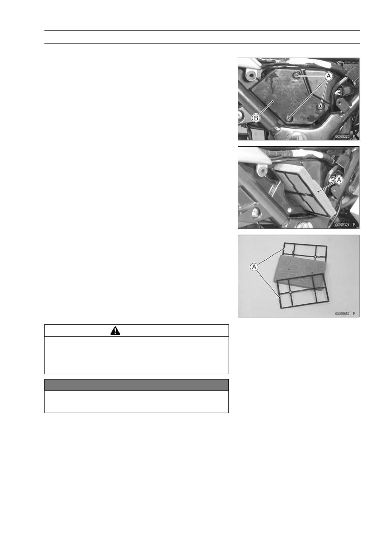
• Remove:
Right Side Cover (see Side Cover Removal in the Frame
chapter)
Air Cleaner Cap Bolts [A]
Air Cleaner Cap [B]
• Pull out the air cleaner element [A].
• Separate the plastic holders [A].
WARNING
If dirt or dust is allowed to pass through into the
carburetor, the throttle may become stuck, possibly
causing accident. Replace the air cleaner element
according to the maintenance chart.
NOTICE
If dirt gets through into the engine, excessive en-
gine wear and possibly engine damage will occur.
2-16 PERIODIC MAINTENANCE
Periodic Maintenance Procedures
WARNING
Gasoline and low-flash point solvents can be
flammable and/or explosive and cause severe
burns. Clean the element in a well ventilated area,
and take care that there is no spark or flame any-
where near the working areas. Do not use gasoline
or low-flash point solvents to clean the element.
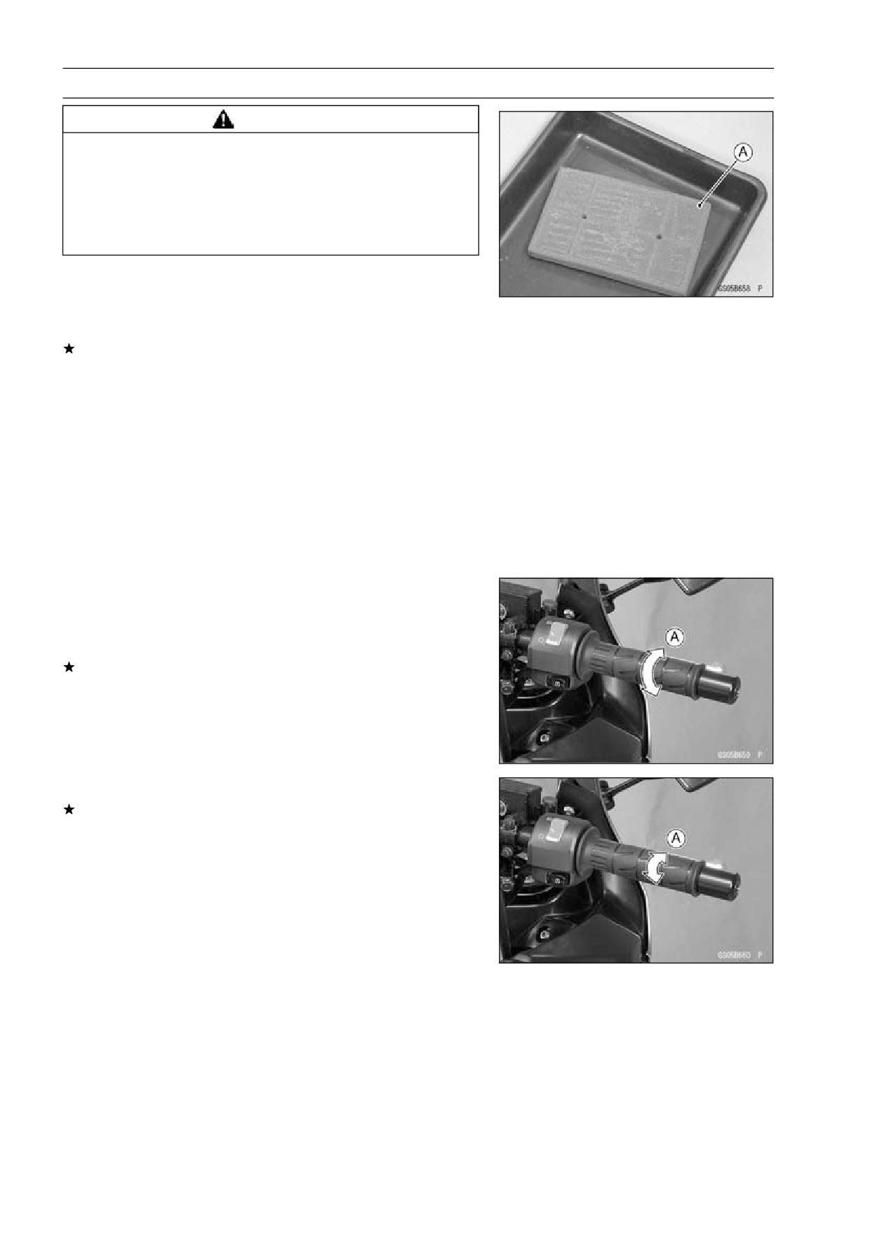
• Clean the element [A] in a bath of high-flash point solvent.
Squeeze it dry in a clean towel. Do not wring the element
or blow it dry; the element can be damaged.
• Check all the parts of the element for visible damage.
If any of the parts of the element are damaged, replace
them.
• After cleaning, saturate the element with a high-quality
foam-air-filter oil, squeeze out the excess, then wrap it in
a clean towel and squeeze it as dry as possible.
○Be careful not to tear the sponge filter.
Air Cleaner Element Installation
• Install the removed parts in reverse of removal.
• Torque the air cleaner cap bolts.
Torque - Air Cleaner Cap Bolts:
2.5 N·m (0.25 kgf·m, 22
in·lb)
Throttle Control System Inspection
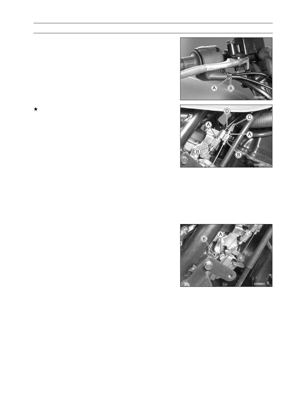
• Check that the throttle grip moves smoothly from full open
to close [A], and the throttle closes quickly and completely
by the return spring in all steering positions.
If the throttle grip doesn’t return properly, check the throt-
tle cable routing, grip free play, and cable damage. Then
lubricate the throttle cable.
• Check the throttle grip free play [A].
If the free play is incorrect, adjust the throttle cable.
Throttle Grip Free Play
Standard:
2∼3mm(0.08∼0.12in.)
PERIODIC MAINTENANCE 2-17
Periodic Maintenance Procedures
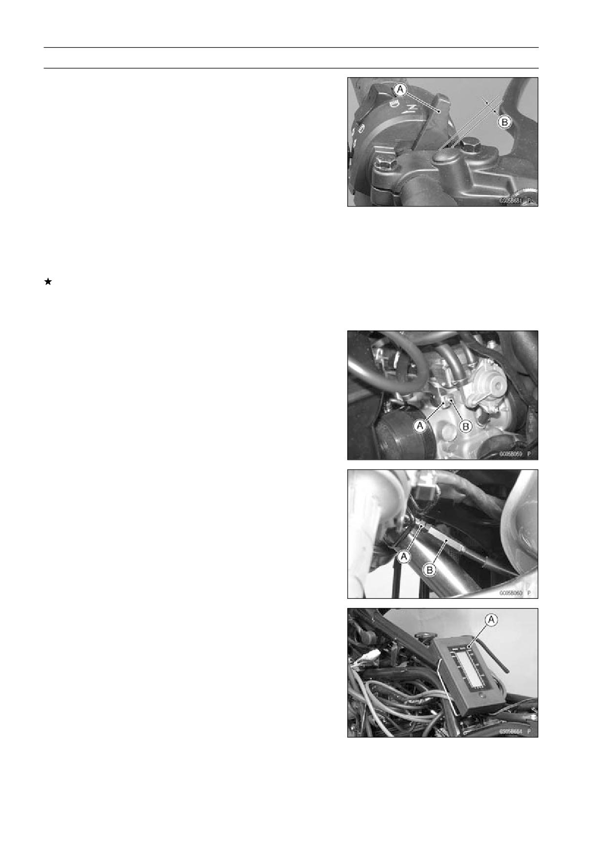
• Loosen the locknut [A], and screw accelerator cable ad-
juster [B] in completely so as to give the throttle grip plenty
of play.
• Turn the accelerator cable adjuster until 2 ∼ 3 mm (0.08 ∼
0.12 in.) of throttle grip play is obtained.
• Tighten the locknut.
If the throttle cables can not be adjusted by using the ca-
ble adjuster at the upper end of the throttle cable, use the
cable adjusters at the lower ends of the throttle cables.
• Remove:
Side Cover (see Side Cover Removal in the Frame chap-
ter)
Right Lower Fairing (see Lower Fairing Removal in the
Frame chapter)
• To make service easy, unscrew the reserver tank bolts
and remove the reserver tank with hoses
• Turn out both upper nuts [A] and turn in both lower nuts [B]
as far as they will go so as to give the throttle grip plenty
of play.
• With the throttle grip completely closed, turn out the lower
nut and turn in the upper nut of the decelerator cable [C]
until the inner cable just becomes tight.
• Turn out the lower nut and turn in the upper nut of the
accelerator cable [D] until the correct free play is obtained.
• Check that the throttle linkage lever [A] stops against the
idle adjusting screw [B] with the throttle grip closed.
2-18 PERIODIC MAINTENANCE
Periodic Maintenance Procedures
Choke Operation Inspection
• Remove:
Front Seat (see Front Seat Removal in the Frame chap-
ter)
Fuel Tank (see Fuel Tank Removal)
Side Covers (see Side Cover Removal in the Frame
chapter)
Lower Fairings (see Lower Fairing Removal in the Frame
chapter)
Fuel Tank (see Fuel Tank Removal)
• Push the choke lever [A] back all the way to its released
position.
• Check choke cable free play [B].
○Determine the amount of choke cable play at the choke
lever.
If the free play is incorrect, adjust the choke cable.
Choke Cable Free Play
Standard: 2 ∼ 3 mm (0.08 ∼ 0.12 in.)
• Push the choke lever back all the way to its released po-
sition.
• Pull the choke lever until the starter plunger lever [A] at the
carburetor touches the starter plunger [B]; the amount of
choke lever travel is the amount of choke cable play.
• Loosen the locknut [A], and turn the adjuster [B] until the
cable has the proper amount of free play.
• Tighten the locknut securely.
Engine Vacuum Synchronization Inspection
• Situate the motorcycle using the center stand so that it is
perpendicular to the ground.
• Remove the fuel tank, and connect the sub-fuel tank to
supply the fuel.
• Remove the right lower fairing.
• Warm up the engine.
• Check the idle speed and adjust if necessary.
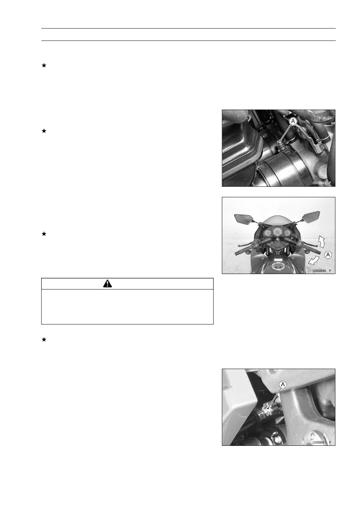
• Pull the vacuum hoses off, and attach vacuum gauge [A]
to the vacuum hose fittings on the carburetors.
Special Tool - Vacuum Gauge KEK-55-5: 57001-1369
PERIODIC MAINTENANCE 2-19
Periodic Maintenance Procedures
• Start the engine and let it idle to measure the carburetor
intake vacuum.
If the intake vacuum difference between the two cylinders
exceeds the limit, adjust the synchronization.
Engine Vacuum Synchronization
Less than 2.7 kPa (2 cmHg) difference between both
cylinders
• Turn the adjusting screw [A] to synchronize the carbure-
tor.
If the carburetor synchronization cannot be obtained by
using the adjusting screw, check for dirt or blockage, and
then check the pilot screw settings.
• Check the Carburetor Synchronization again.
NOTE
○Do not turn the pilot screws carelessly during carburetor
synchronization. You may cause poor running at low
engine speed.
Idle Speed Inspection
• Start the engine and warm it up thoroughly.
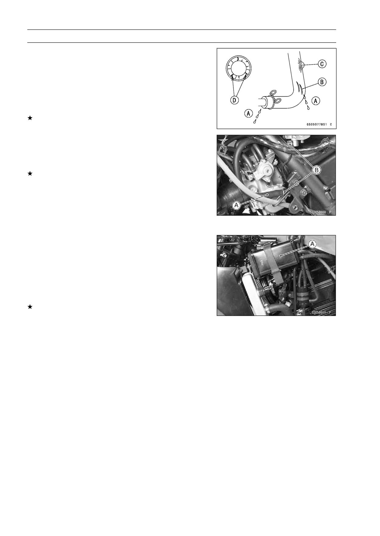
• With the engine idling, turn the handlebar to both sides
[A].
If handlebar movement changes the idle speed, the
throttle cables may be improperly adjusted or incorrectly
routed or damaged. Be sure to correct any of these
conditions before riding (see Throttle Control System
Inspection or Cable, Wire, and Hose Routing section in
the Appendix chapter).
WARNING
Operation with improperly adjusted, incorrectly
routed or damaged cables could result in an unsafe
riding Condition. Follow the service manual to be
make sure to correct any of these conditions.
• Check idle speed.
If the idle speed is out of the specified range, adjust it.
Idle Speed
Standard:
1 300 ±50 r/min (rpm)
Idle Speed Adjustment
• Start the engine and warm it up thoroughly.
• Turn the adjusting screw [A] until the idle speed is correct.
○Open and close the throttle a few times to make sure that
the idle speed is within the specified range. Readjust if
necessary.
2-20 PERIODIC MAINTENANCE
Periodic Maintenance Procedures
Fuel Hose Inspection (fuel leak, damage,
installation condition)
○The fuel hose is designed to be used throughout the mo-
torcycle’s life without any maintenance. However, if the
motorcycle is not properly handled, the high pressure in-
side the fuel line can cause fuel to leak [A] or the hose to
burst. Remove the fuel tank (see Fuel Tank Removal in
the Fuel System chapter) and check the fuel hose.
Replace the fuel hose if any fraying, cracks [B], bulges [C]
or ozone cracks [D] are noticed.
• Check that the hose [A] are securely connected and
clamps [B] are tightened correctly.
• Check that the hoses are routed according to Cable, Wire,
and Hose Routing section in the Appendix chapter.
Replace the hose if it has been sharply bent or kinked.
Evaporative Emission Control System (CAL Model)
Evaporative Emission Control System Inspection
• Inspect the canister as follows.
○Remove:
Left Lower Fairing (see Lower Fairing Removal in the
Frame chapter)
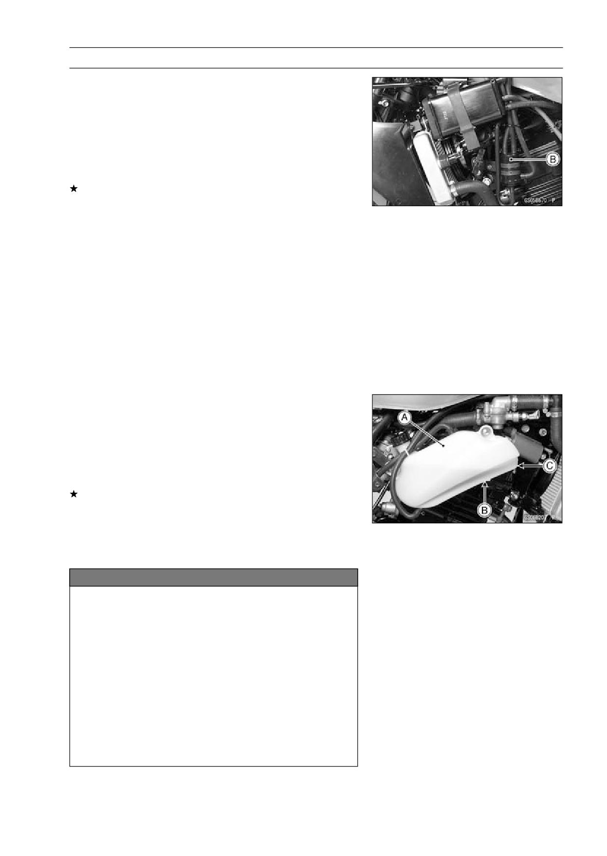
○Remove the canister [A], and disconnect the hoses from
the canister.
○Visually inspect the canister for cracks or other damage.
If the canister has any cracks or bad damage, replace it
with a new one.
NOTE
○The canister is designed to work well through the motor-
cycle’s life without any maintenance if it is used under
normal conditions.
PERIODIC MAINTENANCE 2-21
Periodic Maintenance Procedures
• Check the liquid/vapor separator as follows.
○Remove:
Left Lower Fairing (see Lower Fairing Removal in the
Frame chapter)
○Disconnect the hoses from the separator, and remove the
separator [B] from the motorcycle left side.
○Visually inspect the separator for cracks and other dam-
age.
If the separator has any cracks or damage, replace it with
a new one.
○To prevent the gasoline from flowing into or out of the
canister, hold the separator perpendicular to the ground.
• Check the hoses of the evaporative emission control sys-
tem as follows.
○Check that the hoses are securely connected and clips
are in position.
○Replace any kinked, deteriorated or damaged hoses.
○Route the hoses according to Cable, Wire, and Hose
Routing section in the Appendix chapter.
○When installing the hoses, avoid sharp bending, kinking,
flattening or twisting, and route the hoses with a minimum
of bending so that the emission flow will not be obstructed.
Cooling System
Coolant Level Inspection
NOTE
○Check the level when the engine is cold (room or ambi-
ent temperature).
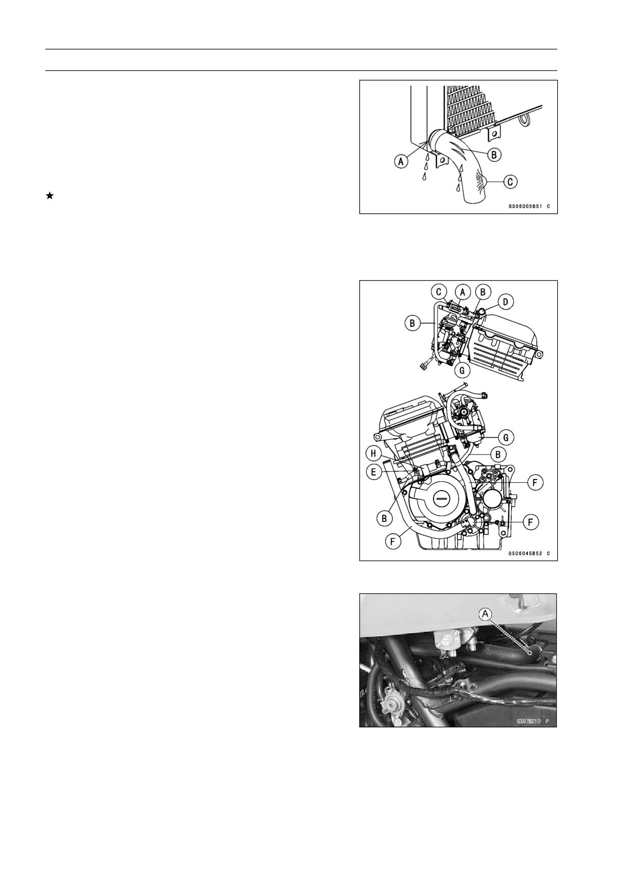
• Check the coolant level in the reserve tank [A] with the
motorcycle held perpendicular (Do not use the sidestand).
If the coolant level is lower than the “L” level line [B], re-
move the right center fairing (see Center Fairing Removal
in the Frame chapter) and unscrew the reserve tank cap,
and add coolant to the “F” level line [C].
“L”: low
“F”: full
NOTICE
For refilling, add the specified mixture of coolant
and soft water. Adding water alone dilutes the
coolant and degrades its anticorrosion properties.
The diluted coolant can attack the aluminum en-
gine parts. In an emergency, soft water alone can
be added. But the diluted coolant must be returned
to the correct mixture ratio within a few days.
If coolant must be added often or the reservoir tank
has run completely dry, there is probably leakage in
the cooling system. Check the system for leaks.
Coolant ruins painted surfaces. Immediately wash
away any coolant that spills on the frame, engine,
wheels or other painted parts.
2-22 PERIODIC MAINTENANCE
Periodic Maintenance Procedures
Radiator Hose Damage and Installation Condition
Inspection
○The high pressure inside the radiator hose and pipe can
cause coolant to leak [A] or the hose to burst if the line is
not properly maintained.
• Visually inspect the hoses for signs of deterioration.
Squeeze the hoses. A hose should not be hard and
brittle, nor should it be soft or swollen.
Replace the hose if any fraying, cracks [B] or bulges [C]
are noticed.
• Check that the hoses are securely connected and clamps
are tightened correctly.
Torque - Radiator Hose Clamp Screws: 3.0 N·m (0.31 kgf·m,
27 in·lb)
Coolant Filter Cleaning (Australia Model)
• Remove the fuel tank (see Fuel Tank Removal in the Fuel
System chapter).
• Drain the coolant (see Coolant Change).
• Remove the filter [A] from the water hoses [B] of carbure-
tor system.
• Blow off dirt and sediment on the filter with compressed
air.
Filter Body [C]
Water Pipe [D]
Coolant Valve Assy [E]
Water Pump [F]
Carburetor [G]
Damper [H]
Air Suction System
Air Suction System Damage Inspection
• Pull the vacuum switch valve hose [A] out of the air
cleaner.
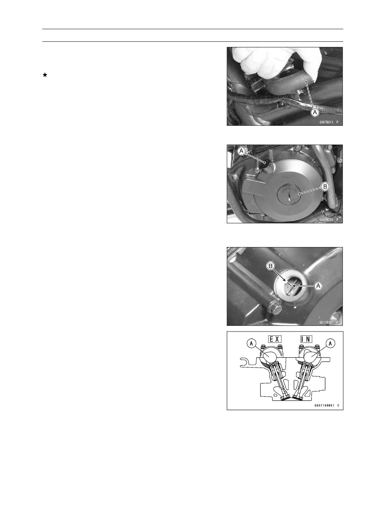
PERIODIC MAINTENANCE 2-23
Periodic Maintenance Procedures
• Start the engine and run it at idle speed.
• Plug [A] the vacuum switch valve hose end with your fin-
ger and feel vacuum pulsing in the hose.
If there is no vacuum pulsation, check the hose line for
leak. If there is no leak, check the vacuum switch valve
or air suction valve (see Engine Top End chapter).
Engine Top End
Valve Clearance Inspection
NOTE
○Valve clearance must be checked and adjusted when
the engine is cold (room temperature).
• Remove:
Cylinder Head Cover (see Cylinder Head Cover Re-
moval in the Engine Top End chapter)
Left Lower Fairing (see Lower Fairing Removal in the
Frame chapter)
• Unscrew the two plugs [A], [B] on the alternator cover.
Special Tool - Filler Cap Driver: 57001-1454
• Check the valve clearance when the pistons are at TDC.
○The pistons are numbered beginning with the engine left
side.
• Using a wrench on the crankshaft rotation bolt, turn the
crankshaft clockwise until the "2/T" [A] mark on the timing
rotor is aligned with the projection [B] in the inspection
window on the alternator cover.
○Measure the valve clearance of the valves for which the
cam [A] are turned away from each other.
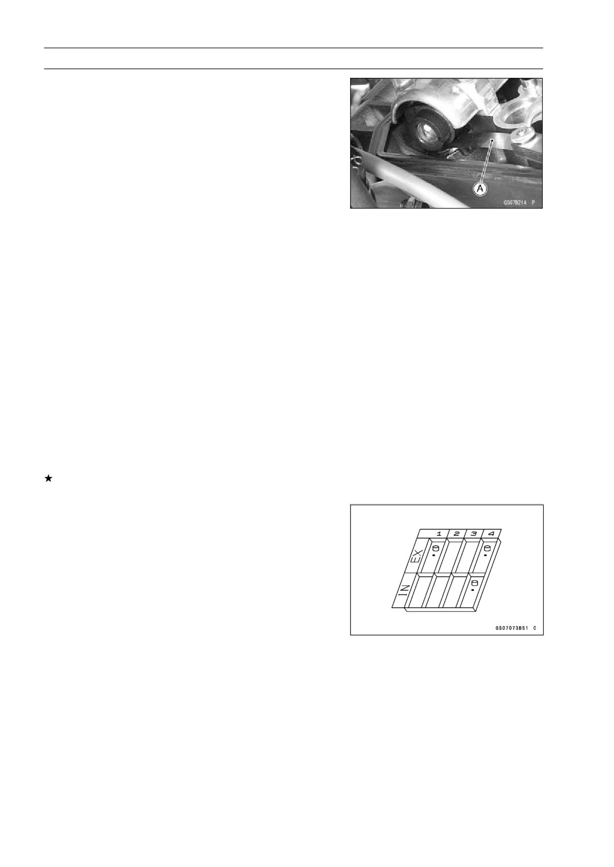
2-24 PERIODIC MAINTENANCE
Periodic Maintenance Procedures
• Using the thickness gauge [A], measure the valve clear-
ance between cam and valve lifter.
Valve Clearance
Standard:
Exhaust
0.22 ∼ 0.29 mm (0.0087 ∼ 0.0114 in.)
Inlet
0.15 ∼ 0.24 mm (0.0059 ∼ 0.0094 in.)
○Each piston has two inlet and two exhaust valves. Mea-
sure these two inlet or exhaust valves at the same crank-
shaft position.
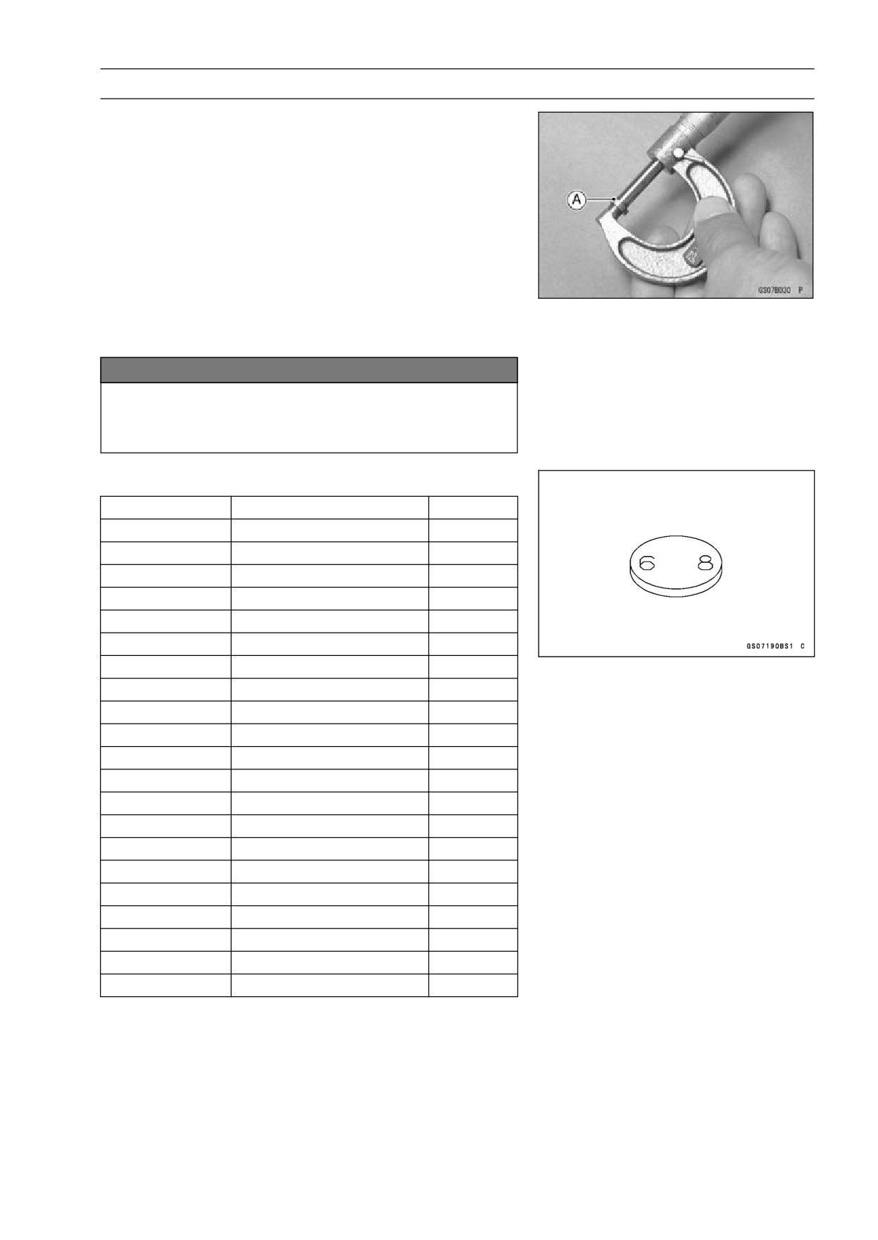
Valve Clearance Measuring Position
#1 Piston TDC at End of Compression Stroke →
Inlet valve clearances of #1 piston, and
Exhaust valve clearances of #1 piston
NOTE
○Check the valve clearance using this method only.
Checking the clearance at any other cam position may
result in improper valve clearance.
Valve Clearance Measuring Position
#2 Piston TDC at End of Compression Stroke →
Inlet valve clearances of #2 piston, and
Exhaust valve clearances of #2 piston
If the valve clearance is not with in the specified range,
first record the clearance, and adjust it.
Valve Clearance Adjustment
• To change the valve clearance, remove the camshaft
chain tensioner, camshafts and valve lifters. Replace the
shim with one of a different thickness.
NOTE
○Mark and record the locations of the valve lifters and
shims so that they can be reinstalled in their original
positions.
PERIODIC MAINTENANCE 2-25
Periodic Maintenance Procedures
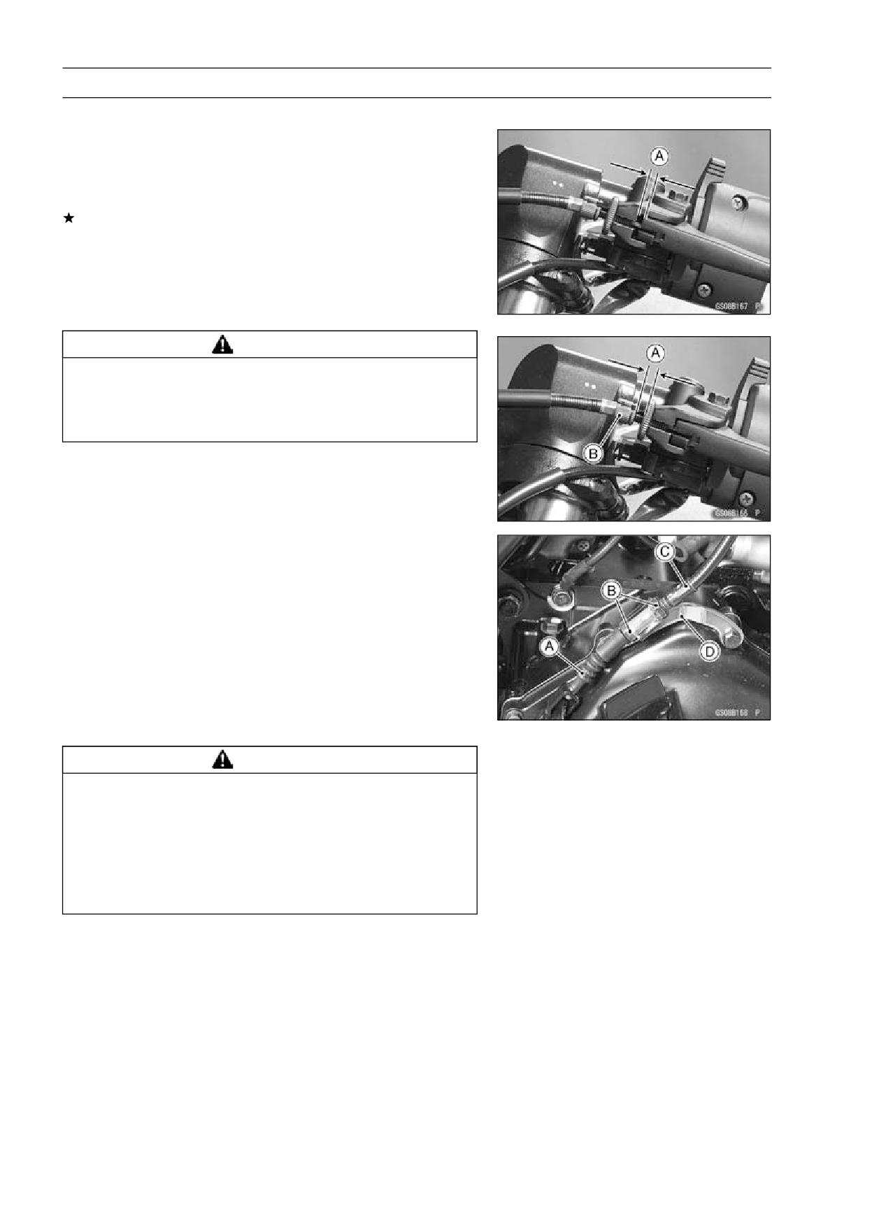
• Clean the shim to remove any dust or oil.
• Measure the thickness of the removed shim [A].
• Select a new shim thickness calculation as follows.
a +b -c = d
[a] Present Shim Thickness
[b] Measured Valve Clearance
[c] Specified Valve Clearance (Mean Value = 0.255 mm
(Exhaust), 0.195 mm (Inlet))
[d] Replace Shim Thickness
Example (Inlet):
2.90 + 0.45 - 0.195 = 3.155 mm
○Exchange the shim for the 3.175 size shim.
NOTICE
Don’t use the shims for another models. This could
cause wear of the valve stem end, and valve stem
damage.
Adjustment Shims
Thickness
Part Number
Mark
2.50
92180-1014
50
2.55
92180-1016
55
2.60
92180-1018
60
2.65
92180-1020
65
2.70
92180-1022
70
2.75
92180-1024
75
2.80
92180-1026
80
2.85
92180-1028
85
2.90
92180-1030
90
2.95
92180-1032
95
3.00
92180-1034
00
3.05
92180-1036
05
3.10
92180-1038
10
3.15
92180-1040
15
3.20
92180-1042
20
3.25
92180-1044
25
3.30
92180-1046
30
3.35
92180-1048
35
3.40
92180-1050
40
3.45
92180-1052
45
3.50
92180-1054
50
2-26 PERIODIC MAINTENANCE
Periodic Maintenance Procedures
Clutch
Clutch Operation Inspection
• Pull the clutch lever just enough to take up the free play
[A].
• Measure the gap between the lever and the lever holder.
If the gap is too wide, the clutch may not release fully. If
the gap is too narrow, the clutch may not engage fully. In
either case, adjust it.
Clutch Lever Free Play
Standard:
2 ∼ 3 mm (0.08 ∼ 0.12 in.)
WARNING
The engine and exhaust system get extremely hot
during normal operation and can cause serious
burns. Never touch the engine or exhaust pipe
during clutch adjustment.
• Turn the adjuster [B] so that 5 ∼ 6 mm (0.20 ∼ 0.24 in.) [A]
of threads are visible.
• Remove the right lower fairing (see Lower Fairing Re-
moval in the Frame chapter).
• Slide the dust cover [A] from the clutch cable lower end
out of place.
• Loosen both adjusting nuts [B] at the clutch cover as far
as they will go.
• Pull the clutch outer cable [C] tight and tighten the adjust-
ing nuts against the bracket [D].
• Slip the rubber dust cover back onto place.
• Turn the adjuster at the clutch lever until the free play is
correct.
WARNING
Too much cable play can prevent clutch disengage-
ment and cause an accident resulting in serious in-
jury or death. When adjusting the clutch or replac-
ing the cable, be sure the upper end of the clutch
outer cable is fully seated in its fitting, or it could
slip into place later, creating enough cable play to
prevent clutch disengagement.
• After the adjustment, start the engine and check that the
clutch does not slip and that it releases properly.
PERIODIC MAINTENANCE 2-27
Periodic Maintenance Procedures
Wheels/Tires
Air Pressure Inspection
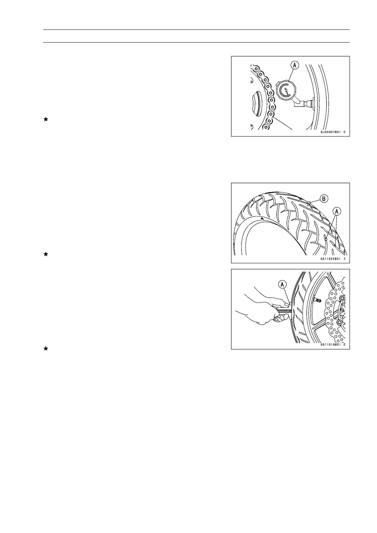
• Remove the air valve cap.
• Measure the tire air pressure with an air pressure gauge
[A] when the tires are cold (that is, when the motorcycle
has not been ridden more than a mile during the past 3
hours).
• Install the air valve cap.
Adjust the tire air pressure according to the specifications
if necessary.
Air Pressure (when Cold)
Front:
Up to 170 kg (375 lb)
200 kPa (2.00 kgf/cm², 28 psi)
Rear:
Up to 170 kg (375 lb)
225 kPa (2.25 kgf/cm², 32 psi)
Wheel/Tire Damage Inspection
• Remove any imbedded stones [A] or other foreign parti-
cles [B] from tread.
• Visually inspect the tire for cracks and cuts, and replace
the tire if necessary. Swelling or high spots indicate inter-
nal damage, requiring tire replacement.
• Visually inspect the wheel for cracks, cuts and dents dam-
age.
If any damage is found, replace the wheel if necessary.
Tire Tread Wear, Abnormal Wear Inspection
As the tire tread wears down, the tire becomes more sus-
ceptible to puncture and failure. An accepted estimate is
that 90% of all tire failures occur during the last 10% of tread
life (90% worn). So it is false economy and unsafe to use
the tires until they are bald.
• Measure the tread depth at the center of the tread with a
depth gauge [A]. Since the tire may wear unevenly, take
measurement at several places.
If any measurement is less than the service limit, replace
the tire (see Tire Removal/Installation in the Wheels/Tires
chapter).
2-28 PERIODIC MAINTENANCE
Periodic Maintenance Procedures
Tread Depth
Standard:
Front:
BRIDGESTONE
4.6 mm (0.181 in.)
DUNLOP
4.5 mm (0.177 in.)
IRC
4.2 mm (0.165 in.)
Rear:
BRIDGESTONE
7.0 mm (0.276 in.)
DUNLOP
7.4 mm (0.291 in.)
IRC
6.5 mm (0.256 in.)
Service Limit:
Front
1 mm (0.04 in.)
Rear
2 mm (0.08 in.)
(Up to 130 km/h (80 mph))
3 mm (0.12 in.)
(Over 130 km/h (80 mph))
WARNING
Some replacement tires may adversely affect han-
dling and cause an accident resulting in serious in-
jury or death. To ensure proper handling and sta-
bility, use only the recommended standard tires for
replacement, inflated to the standard pressure.
NOTE
○Most countries may have their own regulations a mini-
mum tire tread depth: be sure to follow them.
○Check and balance the wheel when a tire is replaced
with a new one.
Wheel Bearing Damage Inspection
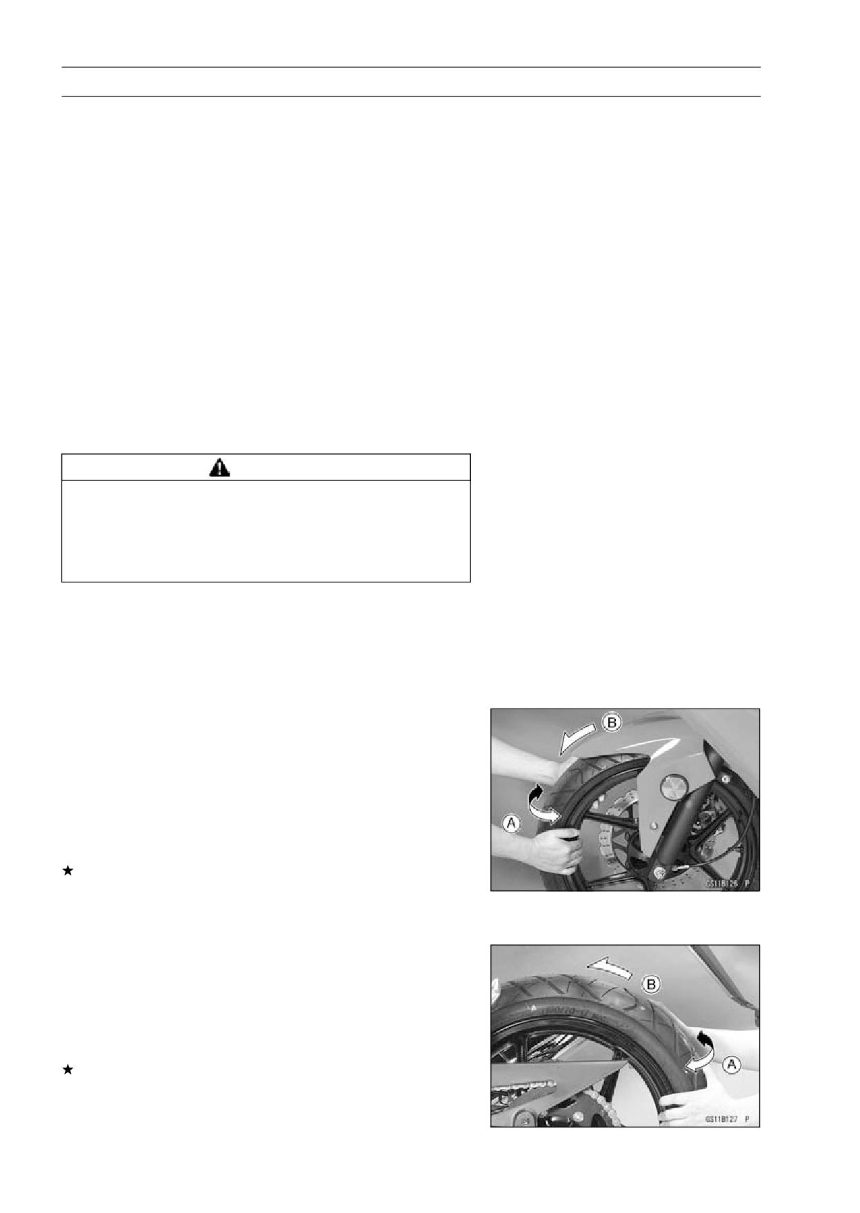
• Raise the front wheel off the ground with jack (see Front
Wheel Removal in the Wheels/Tires chapter).
• Turn the handlebar all the way to the right or left.
• Inspect the roughness of the front wheel bearing by push-
ing and pulling [A] the wheel.
• Spin [B] the front wheel lightly, and check for smoothly
turn, roughness, binding or noise.
If roughness, binding or noise is found, remove the front
wheel and inspect the wheel bearing (see Front Wheel
Removal, Hub Bearing Inspection in the Wheels/Tires
chapter).
• Raise the rear wheel off the ground with stand (see Rear
Wheel Removal in the Wheels/Tires chapter).
• Inspect the roughness of the rear wheel bearing by push-
ing and pulling [A] the wheel.
• Spin [B] the rear wheel lightly, and check for smoothly
turn, roughness, binding or noise.
If roughness, binding or noise is found, remove the rear
wheel and inspect the wheel bearing (see Rear Wheel Re-
moval, Hub Bearing Inspection in the Wheels/Tires chap-
ter) and coupling (see Coupling Bearing Inspection in the
Final Drive chapter).
PERIODIC MAINTENANCE 2-29
Periodic Maintenance Procedures
Drive Train
Drive Chain Lubrication Condition Inspection
• If a special lubricant is not available, a heavy oil such as
SAE 90 is preferred to a lighter oil because it will stay on
the chain longer and provide better lubrication.
• If the chain appears especially dirty, clean it before lubri-
cation.
NOTICE
The O-rings between the side plates seal in the lu-
bricant between the pin and the bushing. To avoid
damaging the O-rings and resultant loss of lubri-
cant, observe the following rules.
Use only kerosene or diesel oil for cleaning an O
-ring drive chain. Any other cleaning solution such
as gasoline or trichloroethylene will cause deterio-
ration and swelling of the O-ring. Immediately blow
the chain dry with compressed air after cleaning.
Complete cleaning and drying the chain within 10
minutes.
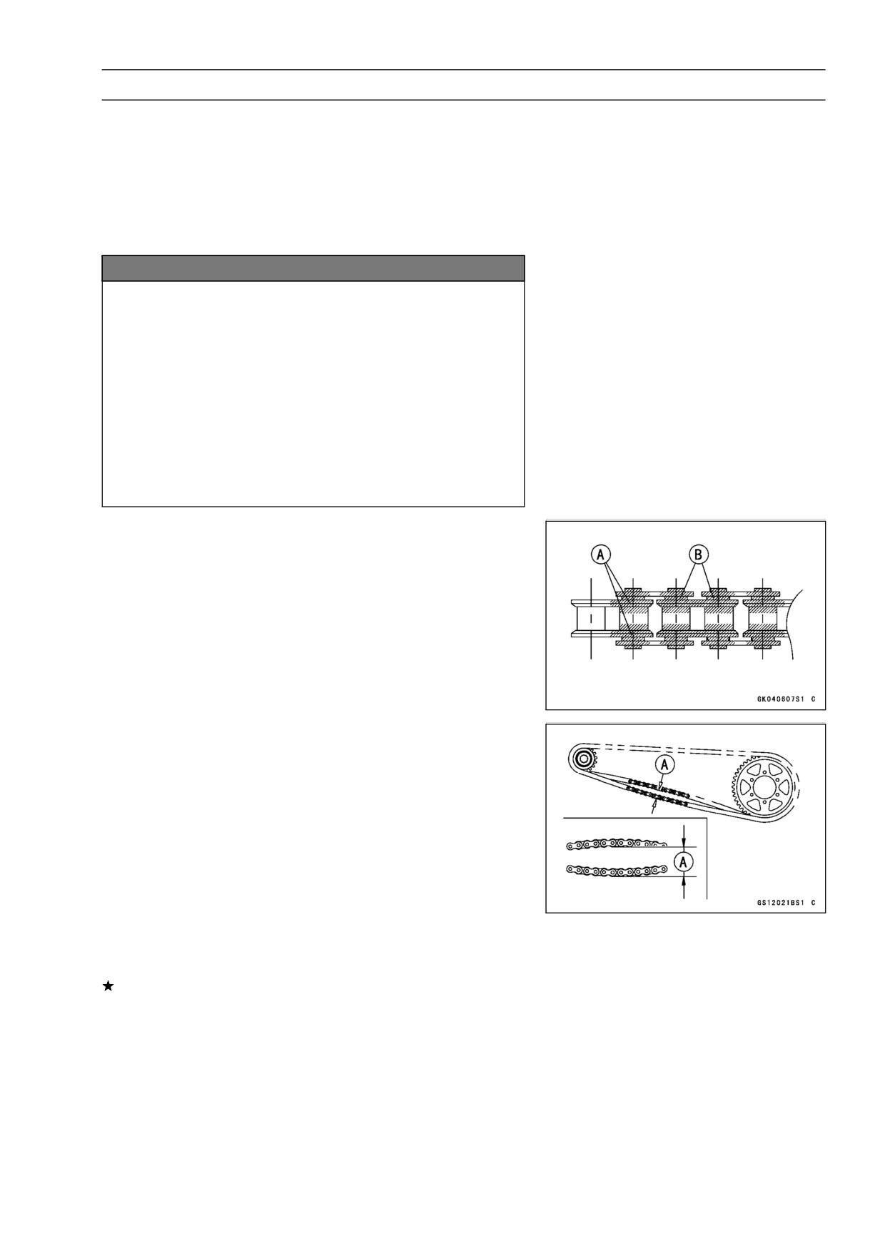
• Apply oil to the sides of the rollers so that oil will penetrate
to the rollers and bushings. Apply the oil to the O-rings so
that the O-rings will be coated with oil.
• Wipe off any excess oil.
Oil Applied Areas [A]
O-rings [B]
Drive Chain Slack Inspection
NOTE
○Check the slack with the motorcycle setting on its side-
stand.
○Clean the chain if it is dirty, and lubricate it if it appears
dry.
• Check the wheel alignment (see Wheel Alignment Inspec-
tion).
• Rotate the rear wheel to find the position where the chain
is tightest.
• Measure the vertical movement (chain slack) [A] midway
between the sprockets.
If the chain slack exceeds the standard, adjust it.
Chain Slack
Standard:
20 ∼ 30 mm (0.8 ∼ 1.2 in.)
2-30 PERIODIC MAINTENANCE
Periodic Maintenance Procedures
Drive Chain Slack Adjustment
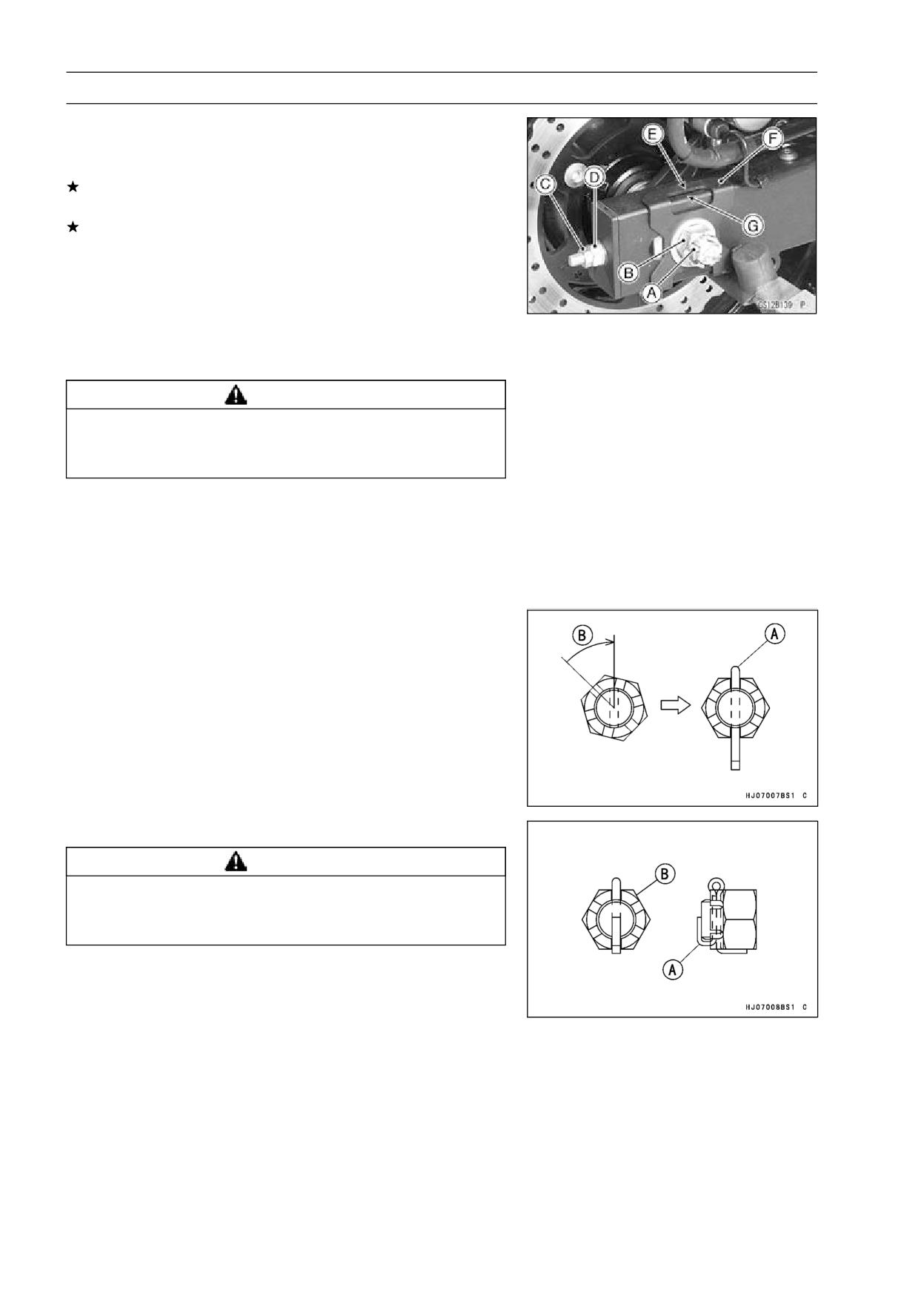
• Remove the cotter pin [A], and loosen the axle nut [B].
• Loosen the both chain adjuster locknuts [C].
If the chain is too loose, turn in the left and right chain
adjuster nuts [D] evenly.
If the chain is too tight, turn out the left and right chain
adjuster nuts evenly, and kick the wheel forward.
• Turn both chain adjuster nuts evenly until the drive chain
has the correct amount of slack. To keep the chain
and wheel properly aligned, the notch [E] on the left
wheel alignment indicator [F] should align with the same
swingarm mark or position [G] that the right indicator
notch aligns with.
WARNING
Misalignment of the wheel will result in abnormal
wear and may result in an unsafe riding condition.
Be sure the wheel is properly aligned.
• Tighten both chain adjuster locknuts securely.
• Tighten the axle nut.
Torque - Rear Axle Nut: 98 N·m (10.0 kgf·m, 72 ft·lb)
• Turn the wheel, measure the chain slack again at the tight-
est position, and readjust if necessary.
• Insert a new cotter pin [A].
NOTE
○When inserting the cotter pin, if the slots in the nut do
not align with the cotter pin hole in the axle, tighten the
nut clockwise [B] up to next alignment.
○It should be within 30°.
○Loosen once and tighten again when the slot goes past
the nearest hole.
• Bend the cotter pin [A] over the nut [B].
WARNING
A loose axle nut can lead to an accident resulting in
serious injury or death. Tighten the axle nut to the
proper torque and install a new cotter pin.
PERIODIC MAINTENANCE 2-31
Periodic Maintenance Procedures
Wheel Alignment Inspection
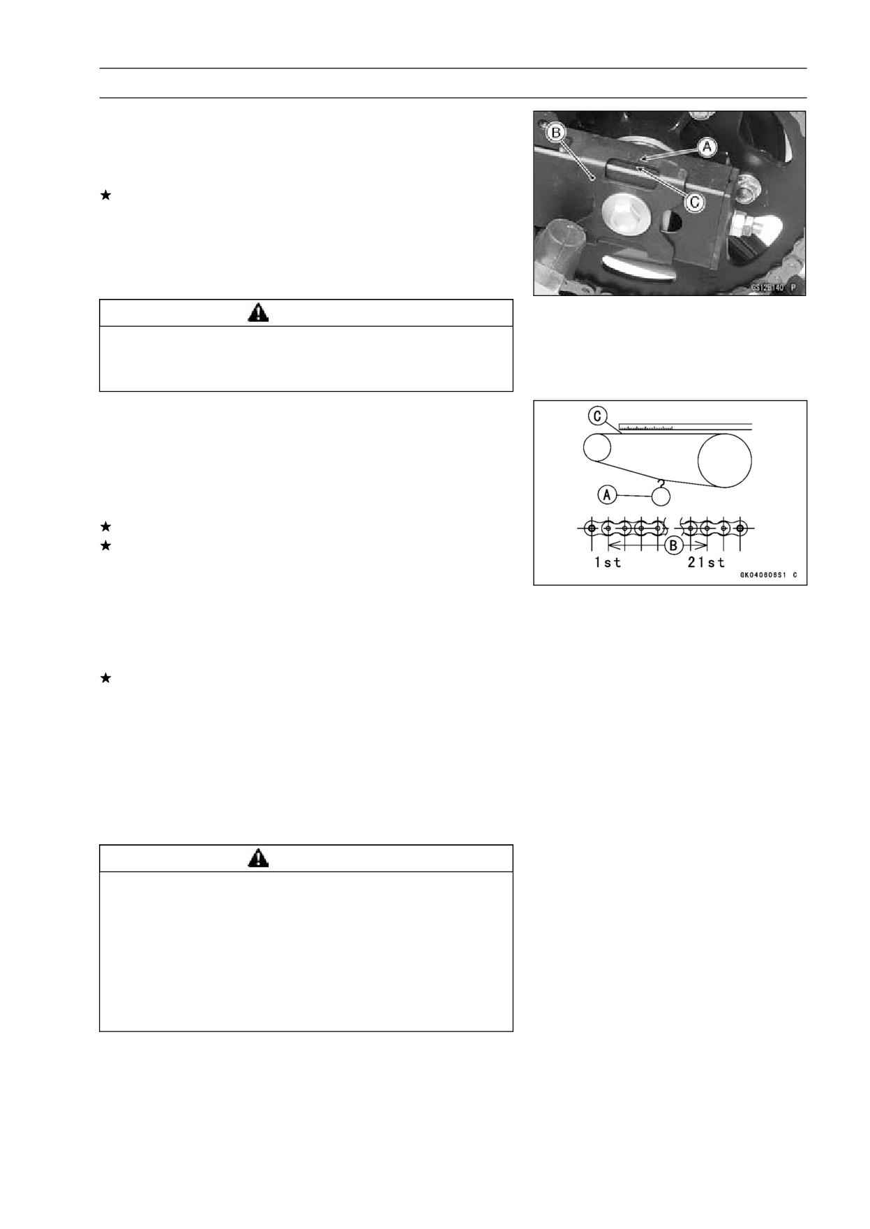
• Check that the notch [A] on the right wheel alignment indi-
cator [B] aligns with the same swingarm mark or position
[C] that the left alignment indicator notch aligns with.
If they do not, adjust the chain slack and align the wheel
alignment (see Drive Chain Slack Adjustment).
NOTE
○Wheel alignment can be also checked using the
straightedge or string method.
WARNING
Misalignment of the wheel will result in abnormal
wear and may result in an unsafe riding condition.
Be sure the wheel is properly aligned.
Drive Chain Wear Inspection
• Remove:
Chain Cover (see Swingarm Removal in the Suspension
chapter)
• Rotate the rear wheel to inspect the drive chain for dam-
aged rollers, and loose pins and links.
If there is any irregularity, replace the drive chain.
Lubricate the drive chain if it appears dry.
• Stretch the chain taut by hanging a 98 N (10 kg, 20 lb)
weight [A] on the chain.
• Measure the length of 20 links [B] on the straight part [C] of
the chain from the pin center of the 1st pin to the pin center
of the 21st pin. Since the chain may wear unevenly, take
measurements at several places.
If any measurements exceed the service limit, replace the
chain. Also, replace the front and rear sprockets when the
drive chain is replaced.
Drive Chain 20-link Length
Standard:
317.5 ∼ 318.2 mm (12.50 ∼ 12.53 in.)
Service Limit:
EX250J8 ∼ JA
323 mm (12.72 in.)
EX250JB ∼ JC
319 mm (12.56 in.)
WARNING
A chain that breaks or jumps off the sprockets
could snag on the engine sprocket or lock the
rear wheel, severely damaging the motorcycle and
causing it to go out of control. Inspect the chain for
damage and proper adjustment before each ride.
If chain wear exceeds the service limit, replace it
with the standard chain. It is an endless type and
should not be cut for installation.
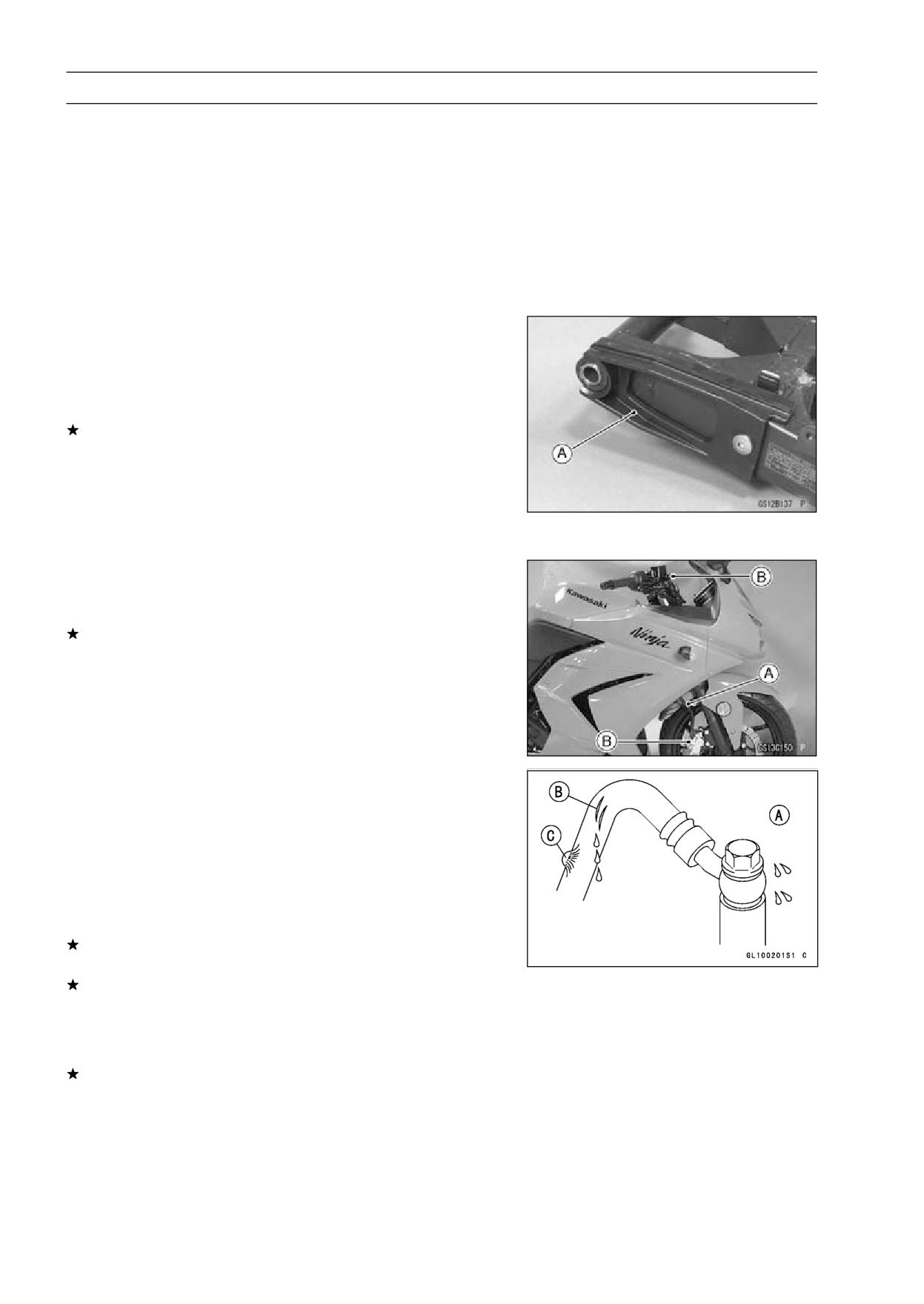
2-32 PERIODIC MAINTENANCE
Periodic Maintenance Procedures
Standard Chain
Make:
EX250J8 ∼ JA
ENUMA
EX250JB ∼ JC
DAIDO
Type:
EX250J8 ∼ JA
EK520SR-O2
EX250JB ∼ JC
DID 520VP2-T
Link:
106 links
Chain Guide Inspection
• Remove:
Swingarm (see Swingarm Removal in the Suspension
chapter)
• Visually inspect the chain guide [A].
Replace the chain guide if it shows any signs of abnormal
wear or damage.
Brake System
Brake Fluid Leak (Brake Hose and Pipe) Inspection
• Apply the brake lever or pedal and inspect the brake fluid
leak from the brake hoses [A] and fittings [B].
If the brake fluid leaked from any position, inspect or re-
place the problem part.
Brake Hose and Pipe Damage and Installation
Condition Inspection
• Inspect the brake hoses and fittings for deterioration,
cracks and signs of leakage.
○The high pressure inside the brake line can cause fluid to
leak [A] or the hose to burst if the line is not properly main-
tained. Bend and twist the rubber hose while examining
it.
Replace the hose and pipe if any crack [B], bulge [C] or
leakage is noticed.
Tighten any brake hose banjo bolts.
Torque - Brake Hose Banjo Bolts: 25 N·m (2.5 kgf·m, 18
ft·lb)
• Inspect the brake hose routing.
If any brake hose routing is incorrect, route the brake hose
according to Cable, Wire, and Hose Routing section in the
Appendix chapter.
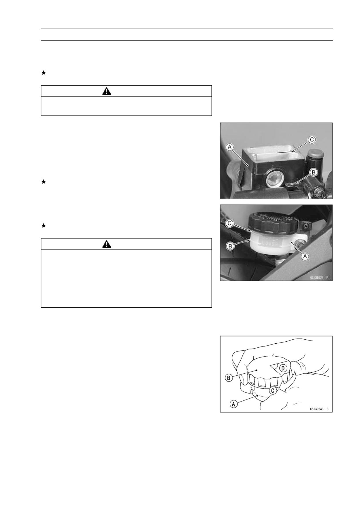
PERIODIC MAINTENANCE 2-33
Periodic Maintenance Procedures
Brake Operation Inspection
• Inspect the operation of the front and rear brake by run-
ning the vehicle on the dry road.
If the brake operation is insufficiency, inspect the brake
system.
WARNING
When test riding the vehicle, be aware of surround-
ing traffic for your safety.
Brake Fluid Level Inspection
• Check that the brake fluid level in the front brake reservoir
[A] is above the lower level line [B].
NOTE
○Hold the reservoir horizontal by turning the handlebar
when checking brake fluid level.
If the fluid level is lower than the lower level line, fill the
reservoir to the upper level line [C] in the reservoir.
• Check that the brake fluid level in the rear brake reservoir
[A] is above the lower level line [B].
If the fluid level is lower than the lower level line, fill the
reservoir to the upper level line [C].
WARNING
Mixing brands and types of brake fluid can reduce
the brake system’s effectiveness and cause an ac-
cident resulting in injury or death. Do not mix two
brands of brake fluid. Change the brake fluid in the
brake line completely if the brake fluid must be re-
filled but the type and brand of the brake fluid that
is already in the reservoir are unidentified.
Recommended Disc Brake Fluid
Grade:
DOT4
• Follow the procedure below to install the rear brake fluid
reservoir cap correctly.
○First, tighten the rear brake fluid reservoir cap [B] clock-
wise [C] by hand until slight resistance is felt indicating
that the cap is seated on the reservoir body, then tighten
the cap an additional 1/6 turn [D] while holding the brake
fluid reservoir body [A].
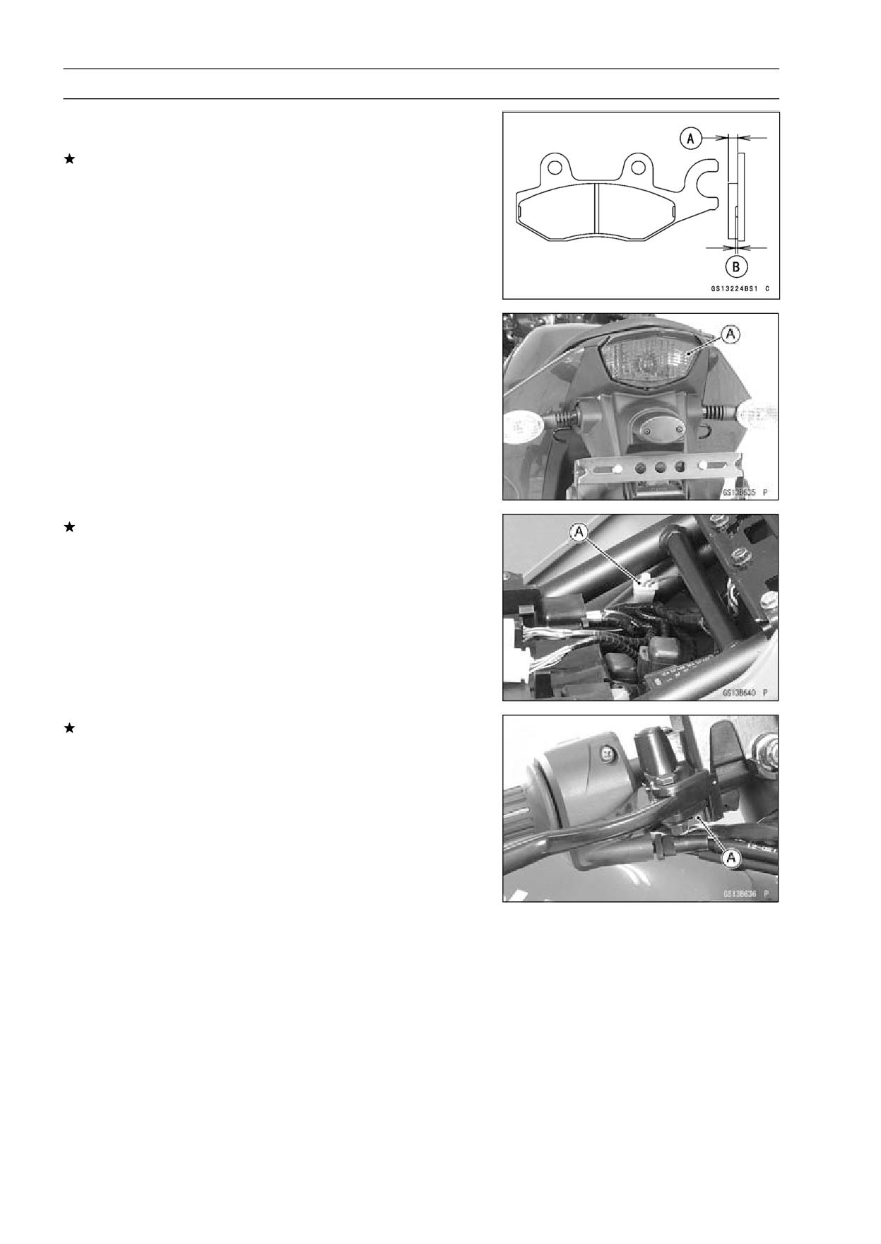
2-34 PERIODIC MAINTENANCE
Periodic Maintenance Procedures
Brake Pad Wear Inspection
• Check the lining thickness [A] of the pads in each caliper.
If the lining thickness of either pad is less than the service
limit [B], replace both pads in the caliper as a set.
Pad Lining Thickness
Standard:
4.5 mm (0.18 in.)
Service Limit:
1 mm (0.04 in.)
Brake Light Switch Operation Inspection
• Turn on the ignition switch.
• The brake light [A] should go on when the brake lever is
applied or after the brake pedal is depressed about 10
mm (0.39 in.).
If it does not, adjust the brake light switch.
• Disconnect the connector [A].
• Turn the brake light switch to adjust the switch.
• Connect the connector.
If it does not go on, inspect or replace the following items.
Battery (see Charging Condition Inspection in the Elec-
trical System chapter)
Brake Light (see Tail/Brake Light Removal in the Electri-
cal System chapter)
Main Fuse 30 A and Taillight Fuse 10 A (see Fuse In-
spection in the Electrical System chapter)
Front Brake Light Switch [A] (see Switch Inspection in
the Electrical System chapter)
Rear Brake Light Switch (see Switch Inspection in the
Electrical System chapter)
Harness (see Wiring Inspection in the Electrical System
chapter)
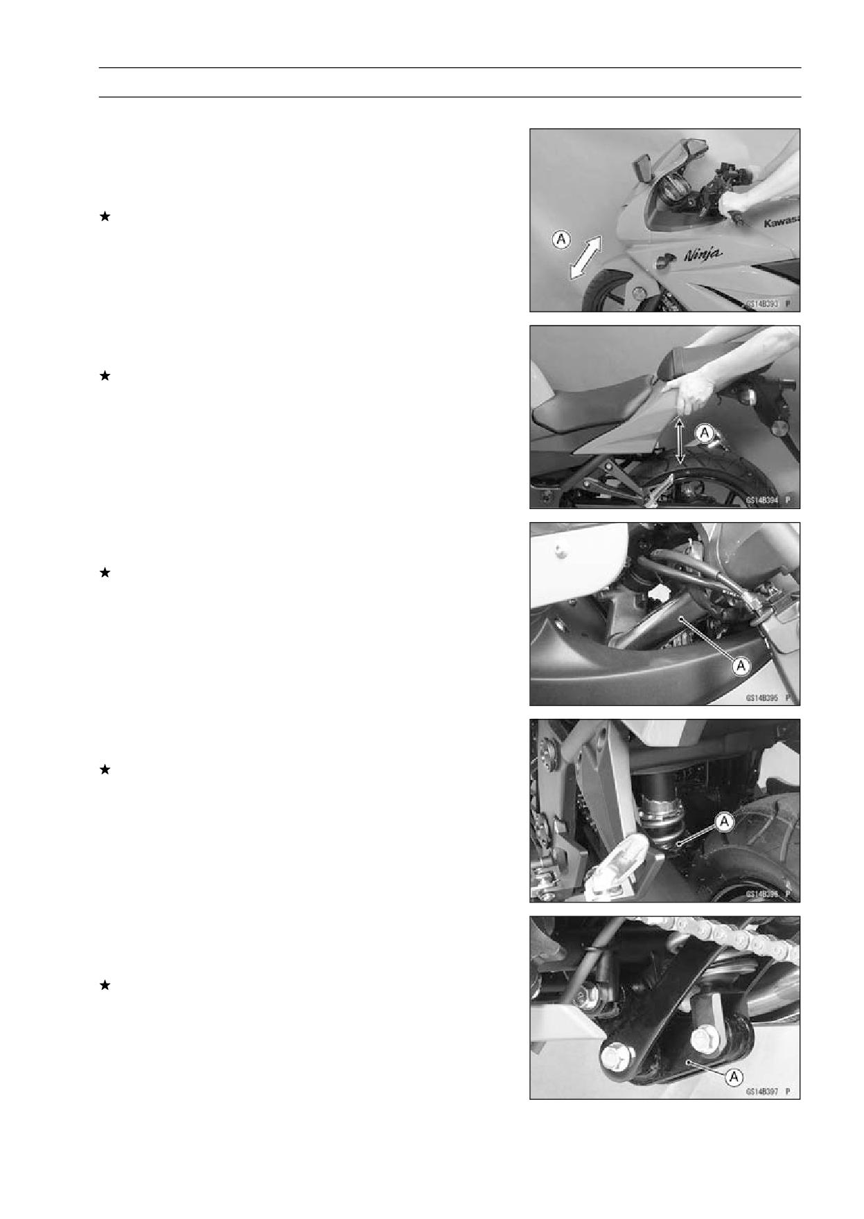
PERIODIC MAINTENANCE 2-35
Periodic Maintenance Procedures
Suspensions
Front Forks/Rear Shock Absorber Operation
Inspection
• Pump the forks down and up [A] 4 or 5 times, and inspect
the smooth stroke.
If the forks do not smoothly or noise is found, inspect the
fork oil level or fork clamps (see Front Fork Oil Change in
the Suspension chapter).
• Pump the seat down and up [A] 4 or 5 times, and inspect
the smooth stroke.
If the shock absorber does not smoothly stroke or noise
is found, inspect the oil leak (see Rear Shock Absorber
Oil Leak Inspection).
Front Fork Oil Leak Inspection
• Visually inspect the front forks [A] for oil leakage.
Replace or repair any defective parts, if necessary.
Rear Shock Absorber Oil Leak Inspection
• Visually inspect the shock absorber [A] for oil leakage.
If the oil leakage is found on it, replace the shock absorber
with a new one.
Rocker Arm Operation Inspection
• Pump the seat down and up 4 or 5 times, and inspect the
smooth stroke.
If the rocker arm [A] does not smoothly stroke or noise
is found, inspect the fasteners and bushings (see Rocker
Arm/Tie-Rod Bushing, Sleeve Inspection in the Suspen-
sion chapter).
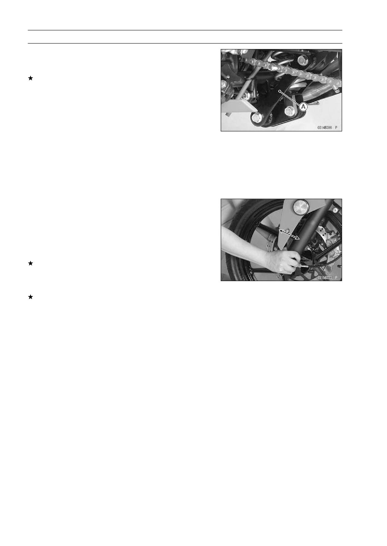
2-36 PERIODIC MAINTENANCE
Periodic Maintenance Procedures
Tie-Rod Operation Inspection
• Pump the seat down and up 4 or 5 times, and inspect the
smooth stroke.
If the tie-rod [A] do not smoothly stroke or noise is found,
inspect the fasteners and tie-rod bushings (see Rocker
Arm/Tie-Rod Bushing, Sleeve Inspection in the Suspen-
sion chapter).
Swingarm Pivot Lubrication
• Remove the swingarm bearing (see Swingarm Bearing
Removal in the Suspension chapter).
• Supply grease to the needle bearings and grease seals
in accordance with the Periodic Maintenance chart.
Steering System
Steering Play Inspection
• Raise the front wheel off the ground with jack (see Front
Wheel Removal in the Wheels/Tires chapter).
• With the front wheel pointing straight ahead, alternately
tap each end of the handlebar. The front wheel should
swing fully left and right from the force of gravity until the
fork hits the stop.
If the wheel binds or catches before the stop, the steering
is too tight.
• Feel for steering looseness by pushing and pulling the
forks.
If you feel looseness, the steering is too loose.
NOTE
○The cables and wiring will have some effect on the mo-
tion of the fork which must be taken into account.
○Be sure the wires and cables are properly routed.
○The bearings must be in good condition and properly
lubricated in order for any test to be valid.
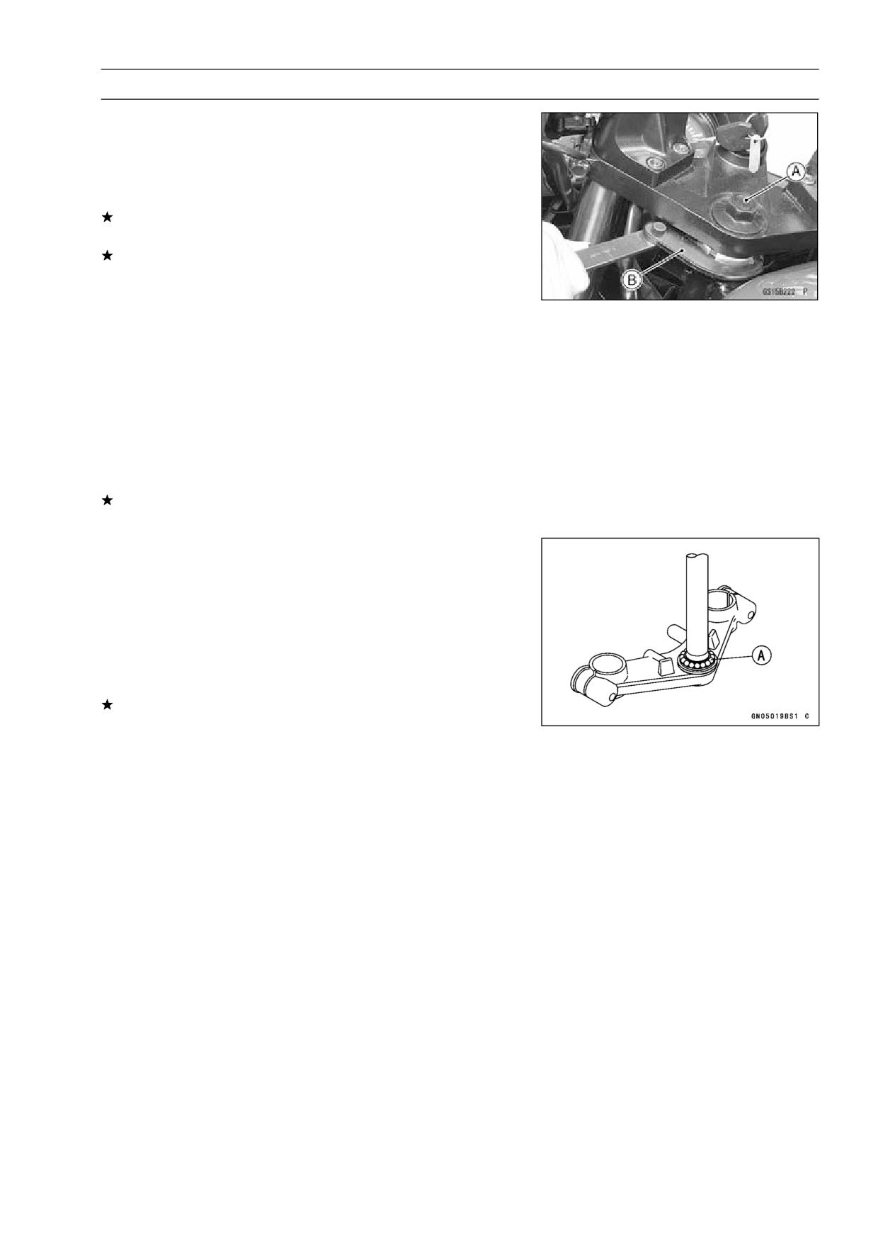
PERIODIC MAINTENANCE 2-37
Periodic Maintenance Procedures
Steering Play Adjustment
• Loosen:
Front Fork Clamp Bolts (lower) (both sides)
Stem Head Bolt [A]
• Adjust the steering.
If the steering is too loose, tighten the steering stem nut
a fraction of a turn using the special tool [B].
If the steering is too tight, loosen the stem nut a fraction
of a turn.
Special Tool - Steering Stem Nut Wrench: 57001-1100
NOTE
○Turn the stem nut 1/8 turn at a time maximum.
• Tighten:
Torque - Steering Stem Head Bolt: 44 N·m (4.5 kgf·m, 32
ft·lb)
Front Fork Clamp Bolts (lower): 30 N·m (3.1 kgf·m,
22 ft·lb)
• Check the steering again.
If the steering is still too tight or too loose, repeat the ad-
justment.
Steering Stem Bearing Lubrication
• Remove the steering stem (see Stem, Stem Bearing Re-
moval in the Steering chapter).
• Using a high-flash point solvent, wash the upper and
lower ball bearings, and wipe the upper and lower outer
races, which are press-fitted into the frame head pipe,
clean off grease and dirt.
• Visually check the outer races and the ball bearings.
Replace them if they show wear or damage.
• Apply a light coat of grease to the upper and lower [A] ball
bearings and outer races.
• Install the steering stem (see Stem, Stem Bearing Instal-
lation in the Steering chapter).
• Adjust the steering (see Steering Play Adjustment).
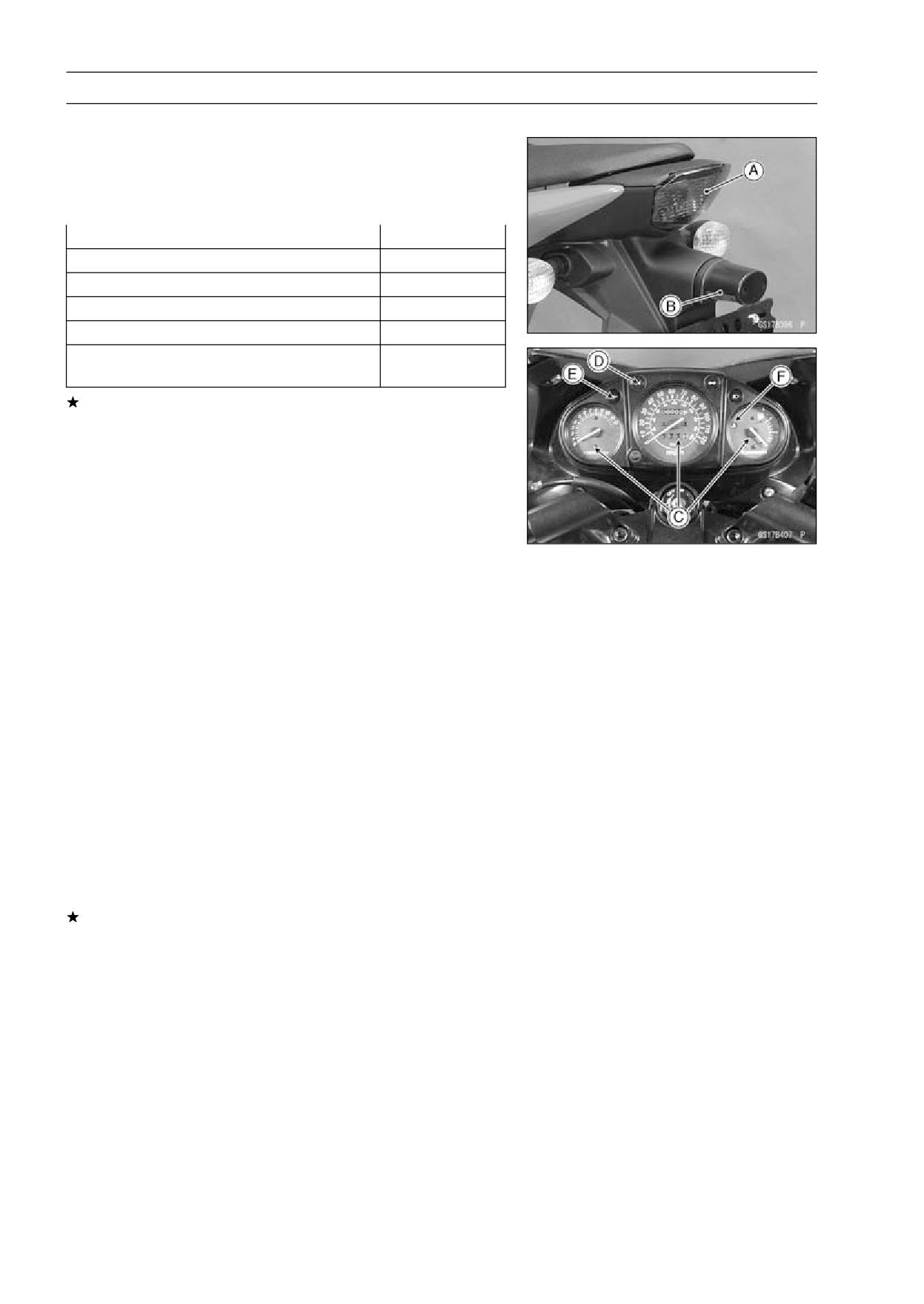
2-38 PERIODIC MAINTENANCE
Periodic Maintenance Procedures
Electrical System
Lights and Switches Operation Inspection
First Step
• Turn on the ignition switch.
• The following lights should go on according to below table.
Taillight [A]
goes on
License Plate Light [B]
goes on
Meter Panel Lights [C]
goes on
Neutral Indicator Light [D]
goes on
Oil Pressure Warning Indicator Light [E]
goes on
Water Temperature Warning Indicator Light
goes on
[F]
If the light does not go on, inspect or replace the following
item.
Battery (see Charging Condition Inspection in the Elec-
trical System chapter)
Applicable Bulb (see Wiring Diagram in the Electrical
System chapter)
Meter Unit for Meter Lights (see Meter Unit Inspection in
the Electrical System chapter)
Meter Unit for Neutral Indicator Light (see Meter Unit
Inspection in the Electrical System chapter)
Meter Unit for Oil Pressure Warning Indicator Light (see
Meter Unit Inspection in the Electrical System chapter)
Meter Unit for Water Temperature Warning Indicator
Light (see Meter Unit Inspection in the Electrical System
chapter)
Main Fuse 30 A and Taillight Fuse 10 A (see Fuse In-
spection in the Electrical System chapter)
Ignition Switch (see Switch Inspection in the Electrical
System chapter)
Neutral Switch (see Switch Inspection in the Electrical
System chapter)
Harness (see Wiring Inspection in the Electrical System
chapter)
• Turn off the ignition switch.
• The all lights should go off.
If the light does not go off, replace the ignition switch.
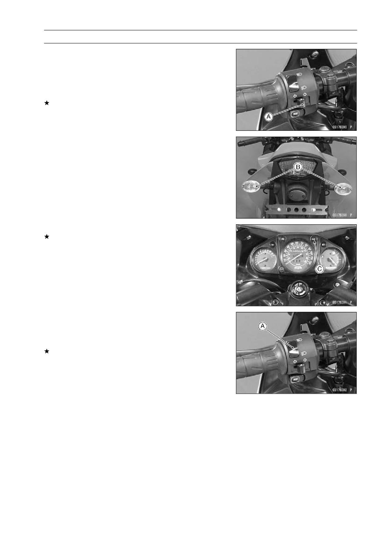
PERIODIC MAINTENANCE 2-39
Periodic Maintenance Procedures
Second Step
• Turn on the turn signal switch [A] (left or right position).
• The left or right turn signal lights [B] (front and rear) ac-
cording to the switch position should flash.
• The turn signal indicator light [C] in the meter unit should
flash.
If the each light does not flash, inspect or replace the
following item.
Turn Signal Light Bulb (see Turn Signal Light Bulb Re-
placement in the Electrical System chapter)
Meter Unit for Turn Signal Light Indicator Light (see Me-
ter Unit Inspection in the Electrical System chapter)
Turn Signal Relay Fuse 10 A (see Fuse Inspection in the
Electrical System chapter)
Turn Signal Switch (see Switch Inspection in the Electri-
cal System chapter)
Turn Signal Relay (see Turn Signal Relay Inspection in
the Electrical System chapter)
Harness (see Wiring Inspection in the Electrical System
chapter)
• Push the turn signal switch.
• The turn signal lights and indicator light should go off.
If the light does not go off, inspect or replace the following
item.
Turn Signal Switch (see Switch Inspection in the Electri-
cal System chapter)
Turn Signal Relay (see Turn Signal Relay Inspection in
the Electrical System chapter)
Third Step
• Set the dimmer switch [A] to low beam position.
• Start the engine.
• The low beam headlight should go on.
If the low beam headlight does not go on, inspect or re-
place the following item.
Headlight Low Beam Bulb (see Headlight Bulb Replace-
ment in the Electrical System chapter)
Headlight Fuse 10 A (see Fuse Inspection in the Electri-
cal System chapter)
Dimmer Switch (see Switch Inspection in the Electrical
System chapter)
Headlight Relay (see Relay Circuit Inspection in the
Electrical System chapter)
Harness (see Wiring Inspection in the Electrical System
chapter)
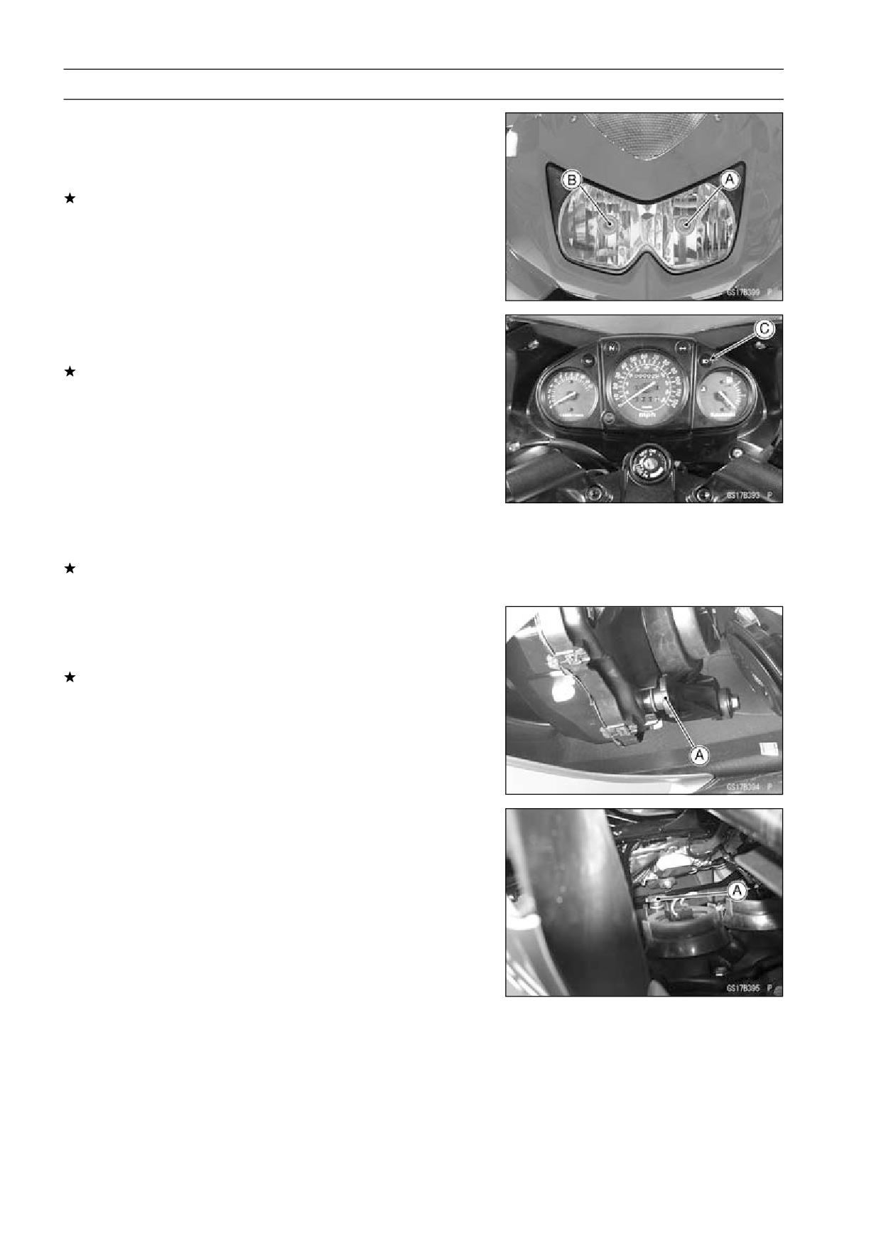
2-40 PERIODIC MAINTENANCE
Periodic Maintenance Procedures
• Set the dimmer switch to high beam position.
• The low beam [A] and high beam [B] headlights should
go on.
• The high beam indicator light [C] should go on.
If the high beam headlight and/or high beam indicator light
does not go on, inspect or replace the following item.
Headlight High Beam Bulb (see Headlight Bulb Replace-
ment in the Electrical System chapter)
Dimmer Switch (see Switch Inspection in the Electrical
System chapter)
• Turn off the engine stop switch.
• The low beam and high beam headlights should stay go-
ing on.
If the headlights and high beam indicator light does go off,
inspect or replace the following item.
Headlight Relay (see Relay Circuit Inspection in the
Electrical System chapter)
• Turn off the ignition switch.
• The headlights and high beam indicator light should go
off.
Headlight Aiming Inspection
• Inspect the headlight beam for aiming.
If the headlight beam points to one side rather than
straight ahead, adjust the horizontal beam.
Headlight Beam Horizontal Adjustment
• Turn the horizontal adjuster [A] on the headlight with the
screwdriver in or out until the beam points straight ahead.
If the headlight beam points too low or high, adjust the
vertical beam.
Headlight Beam Vertical Adjustment
• Turn the vertical adjuster [A] on the headlight with the
screwdriver in or out to adjust the headlight vertically.
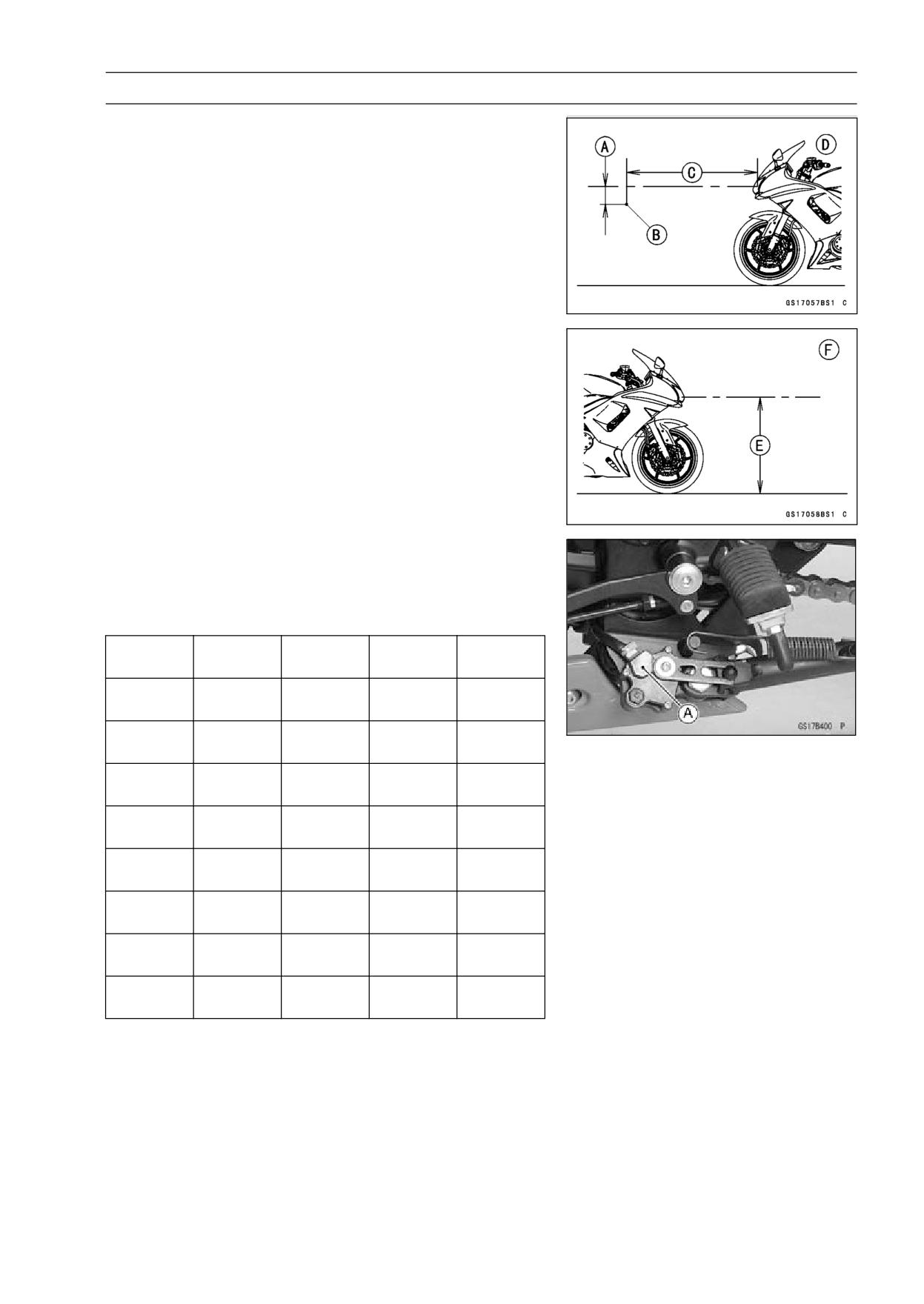
PERIODIC MAINTENANCE 2-41
Periodic Maintenance Procedures
NOTE
○ON high beam, the brightest points should be slightly
below horizontal with the motorcycle on its wheels and
the rider seated. Adjust the headlight to the proper an-
gle according to local regulations.
○For US model, the proper angle is 0.4 degrees below
horizontal. This is 50 mm (2 in.) drop at 7.6 m (25
ft) measured from the center of the headlight with the
motorcycle on its wheels and the rider seated.
50 mm (2 in.) [A]
Center of Brightest Spot [B]
7.6 m (25 ft) [C]
Low Beam [D]
Height of Headlight Center [E]
High Beam [F]
Sidestand Switch Operation Inspection
• Inspect the sidestand switch [A] operation accordance to
below table.
Sidestand Switch Operation
Gear
Clutch
Engine
Engine
Sidestand
Position
Lever
Start
Run
Continue
Up
Neutral
Released
Starts
running
Continue
Up
Neutral
Pulled in
Starts
running
Doesn’t
Up
In Gear
Released
Stops
start
Continue
Up
In Gear
Pulled in
Starts
running
Continue
Down
Neutral
Released
Starts
running
Continue
Down
Neutral
Pulled in
Starts
running
Doesn’t
Down
In Gear
Released
Stops
start
Doesn’t
Down
In Gear
Pulled in
Stops
start
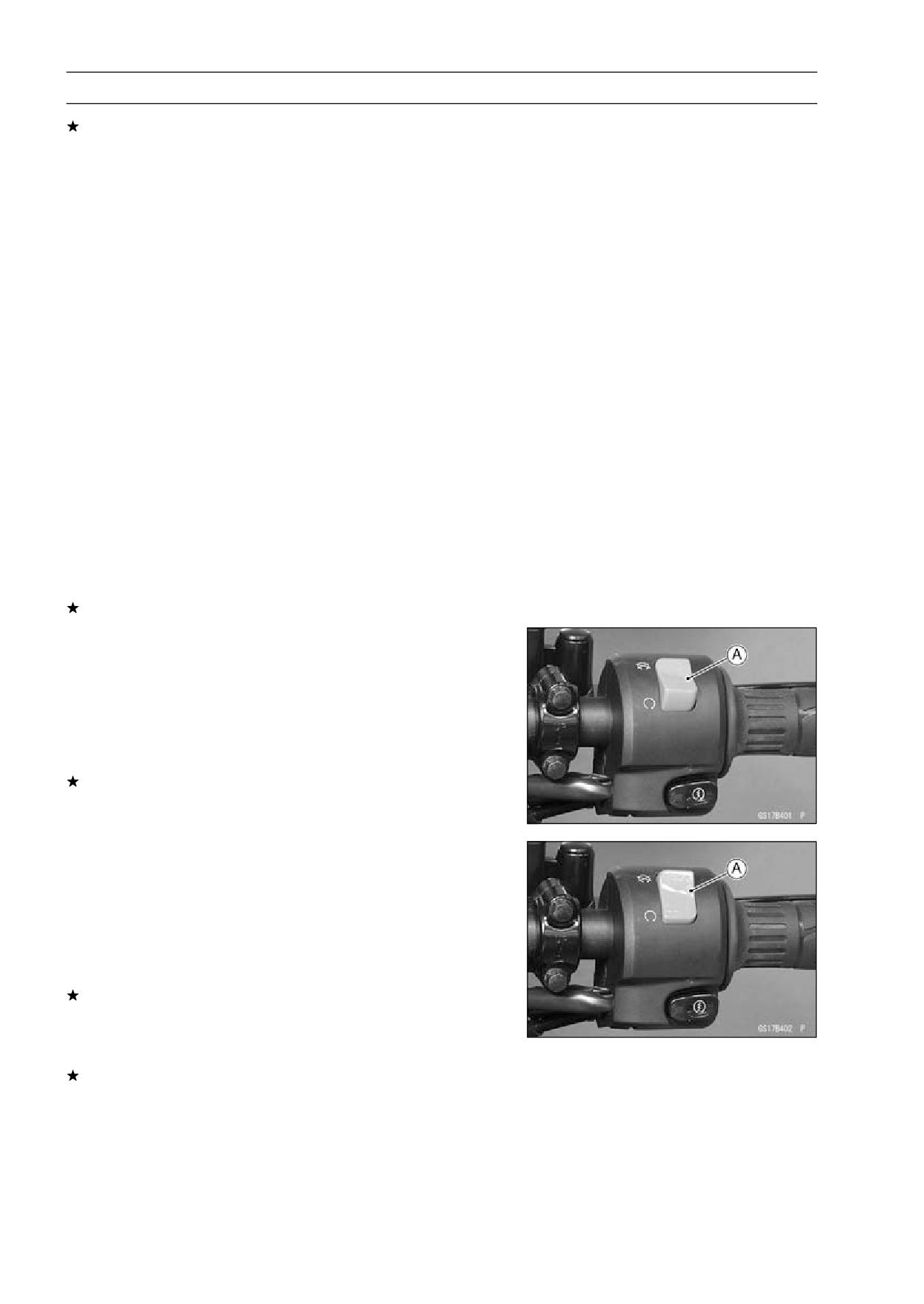
2-42 PERIODIC MAINTENANCE
Periodic Maintenance Procedures
If the sidestand switch operation does not work, inspect
or replace the following item.
Battery (see Charging Condition Inspection in the Elec-
trical System chapter)
Main Fuse 30 A (see Fuse Inspection in the Electrical
System chapter)
Ignition Fuse 10 A (see Fuse Inspection in the Electrical
System chapter)
Ignition Switch (see Switch Inspection in the Electrical
System chapter)
Sidestand Switch (see Switch Inspection in the Electrical
System chapter)
Engine Stop Switch (see Switch Inspection in the Elec-
trical System chapter)
Starter Button (see Switch Inspection in the Electrical
System chapter)
Neutral Switch (see Switch Inspection in the Electrical
System chapter)
Starter Relay (see Starter Relay Inspection in the Elec-
trical System chapter)
Starter Circuit Relay (see Relay Circuit Inspection in the
Electrical System chapter)
Harness (see Wiring Inspection in the Electrical System
chapter)
If the all parts are good condition, replace the IC Igniter.
Engine Stop Switch Operation Inspection
First Step
• Turn on the ignition switch.
• Set the neutral position.
• Turn the engine stop switch to stop position [A].
• Push the starter button.
• The engine does not start.
If the engine starts, inspect or replace the following item.
Engine Stop Switch (see Switch Inspection in the Elec-
trical System chapter)
Second Step
• Turn on the ignition switch.
• Set the neutral position.
• Turn the engine stop switch to run position [A].
• Push the starter button and run the engine.
• Turn the engine stop switch to stop position.
• Immediately the engine should be stop.
If the engine does not stop, inspect or replace the follow-
ing item.
Engine Stop Switch (see Switch Inspection in the Elec-
trical System chapter)
If the engine stop switch is good condition, replace the IC
Igniter.
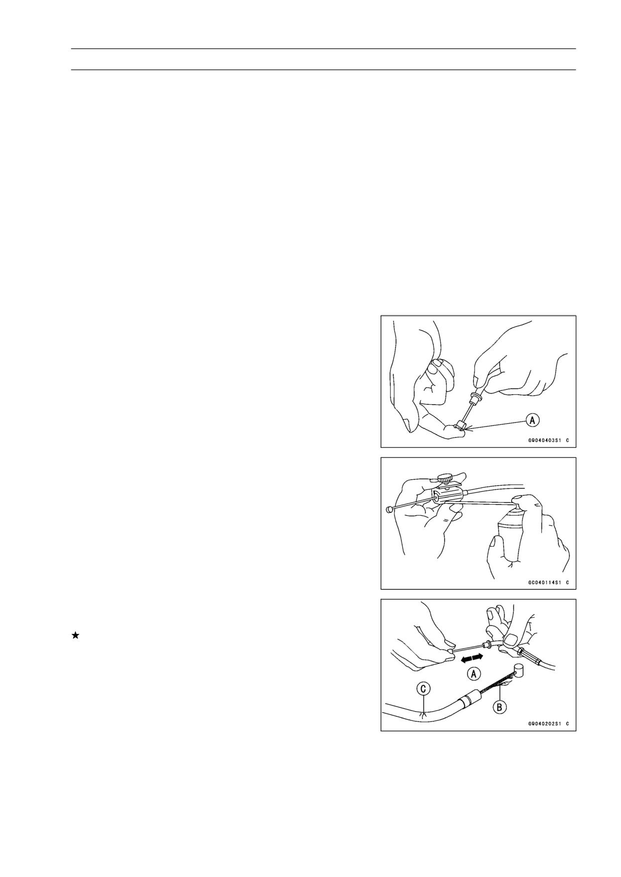
PERIODIC MAINTENANCE 2-43
Periodic Maintenance Procedures
Others
Chassis Parts Lubrication
• Before lubricating each part, clean off any rusty spots with
rust remover and wipe off any grease, oil, dirt, or grime.
• Lubricate the points listed below with indicated lubricant.
NOTE
○Whenever the vehicle has been operated under
wet or rainy conditions, or especially after using a
high-pressure water spray, perform the general lubri-
cation.
Pivots: Lubricate with Grease.
Brake Lever
Brake Pedal
Clutch Lever
Rear Brake Joint Pin
Sidestand
Points: Lubricate with Grease.
Clutch Inner Cable Upper and Lower Ends [A]
Throttle Inner Cable Upper and Lower Ends
Cables: Lubricate with Rust Inhibitor.
Clutch Cable
Throttle Cables
• Lubricate the cables by seeping the oil between the cable
and housing.
○The cable may be lubricated by using a commercially
available pressure cable lubricator with an aerosol cable
lubricant.
• With the cable disconnected at both ends, the inner cable
should move freely [A] within the cable housing.
If cable movement is not free after lubricating, if the cable
is frayed [B], or if the cable housing is kinked [C], replace
the cable.
2-44 PERIODIC MAINTENANCE
Periodic Maintenance Procedures
Bolts, Nuts and Fasteners Tightness Inspection
• Check the tightness of the bolts and nuts listed here. Also,
check to see that each cotter pin is in place and in good
condition.
NOTE
○For the engine fasteners, check the tightness of them
when the engine is cold (at room temperature).
If there are loose fasteners, retighten them to the spec-
ified torque following the specified tightening sequence.
Refer to the appropriate chapter for torque specifications.
If torque specifications are not in the appropriate chapter,
see the Standard Torque Table. For each fastener, first
loosen it by 1/2 turn, then tighten it.
If cotter pins are damaged, replace them with new ones.
Bolt, Nut and Fastener to be checked
Engine:
Clutch Lever Pivot Nut
Engine Mounting Bolts and Nuts
Exhaust Pipe Manifold Holder Nuts
Muffler Body Mounting Bolts
Wheels:
Front Axle
Rear Axle Nut
Rear Axle Nut Cotter Pin
Brakes:
Brake Lever Pivot Nut
Brake Pedal Bolt
Brake Rod Joint Cotter Pin
Caliper Mounting Bolts
Front Master Cylinder Clamp Bolts
Rear Master Cylinder Mounting Bolts
Suspension:
Front Fork Clamp Bolts
Rear Shock Absorber Bolt and Nut
Swingarm Pivot Shaft Nut
Steering:
Steering Stem Head Bolt
Handlebar Holder Bolts
Others:
Footpeg Stay Bolts
Front Fender Bolts
Sidestand Bolt
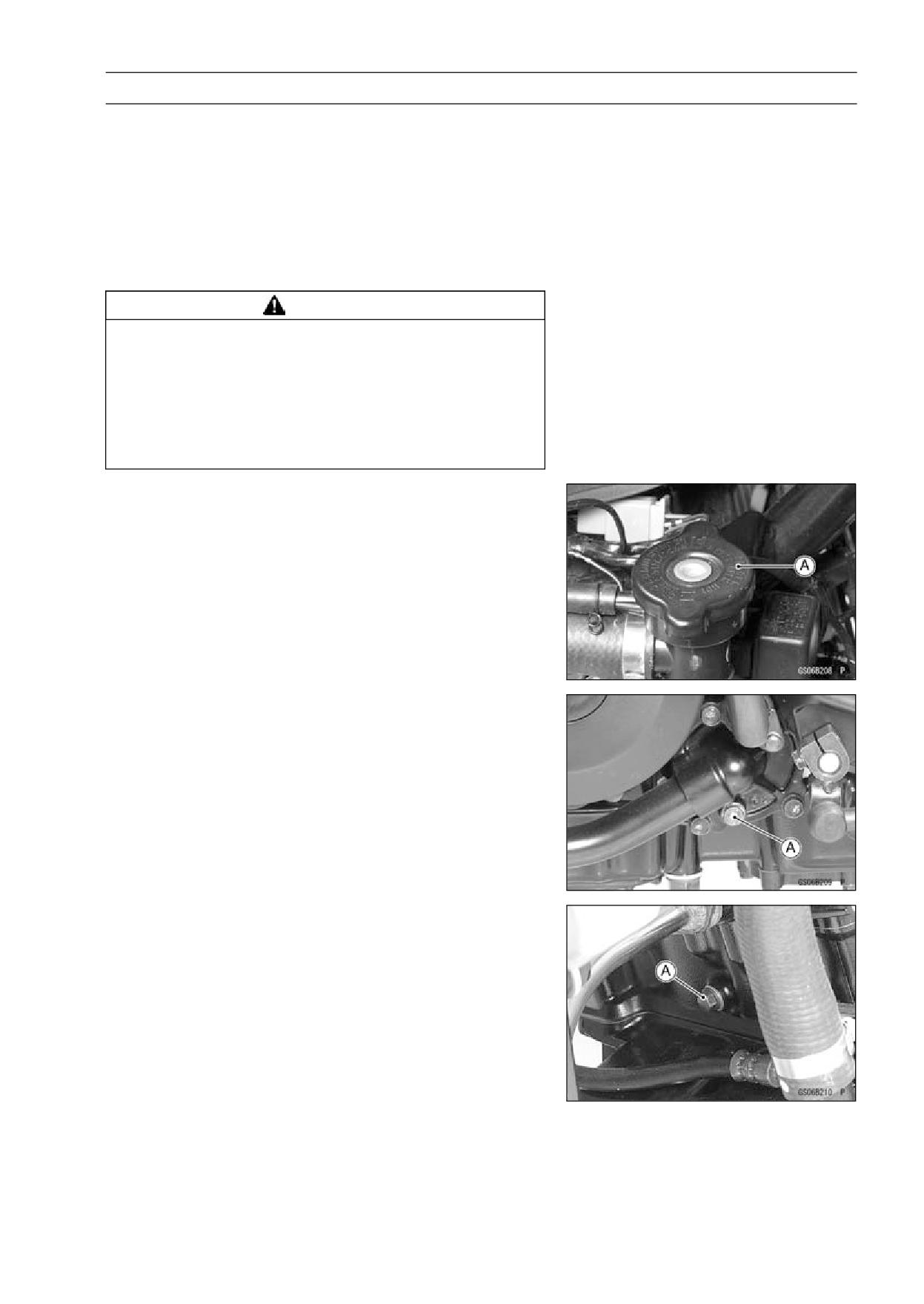
PERIODIC MAINTENANCE 2-45
Periodic Maintenance Procedures
Replacement Parts
Air Cleaner Element Replacement
• Refer to the Air Cleaner Element Cleaning (see Air
Cleaner Element Cleaning).
Fuel Hose Replacement
• Refer to Fuel Hose Inspection (see Fuel Hose Inspection).
Coolant Change
WARNING
Coolant can be extremely hot and cause severe
burns, is toxic and very slippery. Do not remove
the radiator cap or attempt to change the coolant
when the engine is hot; allow it cool completely.
Immediately wipe any spilled coolant from tires,
frame, engine or other painted parts. Do not ingest
coolant.
• Remove:
Lower Fairings (see Lower Fairing Removal in the Frame
chapter)
Radiator Cap [A]
• Place a container under the drain bolts [A] at the bottom
of the water pump cover and cylinder.
• Drain the coolant from the radiator and engine by remov-
ing the drain bolts.
Torque - Drain Bolt: 9.8 N·m (1.0 kgf·m, 87 in·lb)
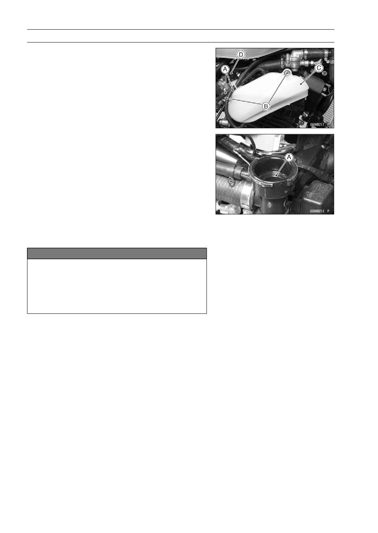
2-46 PERIODIC MAINTENANCE
Periodic Maintenance Procedures
• Remove:
Hoses [A]
Mounting Bolts [B] and Reserve Tank [C]
• Remove the cap [D] and pour the coolant of the reserve
tank into the container.
• Install:
Hoses
Reserve Tank
• Tighten the drain bolt with the specified torque.
Torque - Drain Bolt: 9.8 N·m (1.0 kgf·m, 87 in·lb)
• Fill the radiator up to the radiator filler neck [A] with
coolant, and install the radiator cap.
NOTE
○Pour in the coolant slowly so that it can expel the air
from the engine and radiator.
• Fill the reserve tank up to the full level line with coolant,
and install the cap.
NOTICE
Soft or distilled water must be used with the an-
tifreeze (see below for antifreeze) in the cooling sys-
tem.
If hard water is used in the system, it causes scales
accumulation in the water passages, and consider-
ably reduces the efficiency of the cooling system.
Water and Coolant Mixture Ratio (Recommended)
Soft Water:
50%
Coolant:
50%
Freezing Point: -35°C (-31°F)
Capacity:
1.5 L (1.59 US qt)
NOTE
○Choose a suitable mixture ratio by referring to the
coolant manufacturer’s directions.
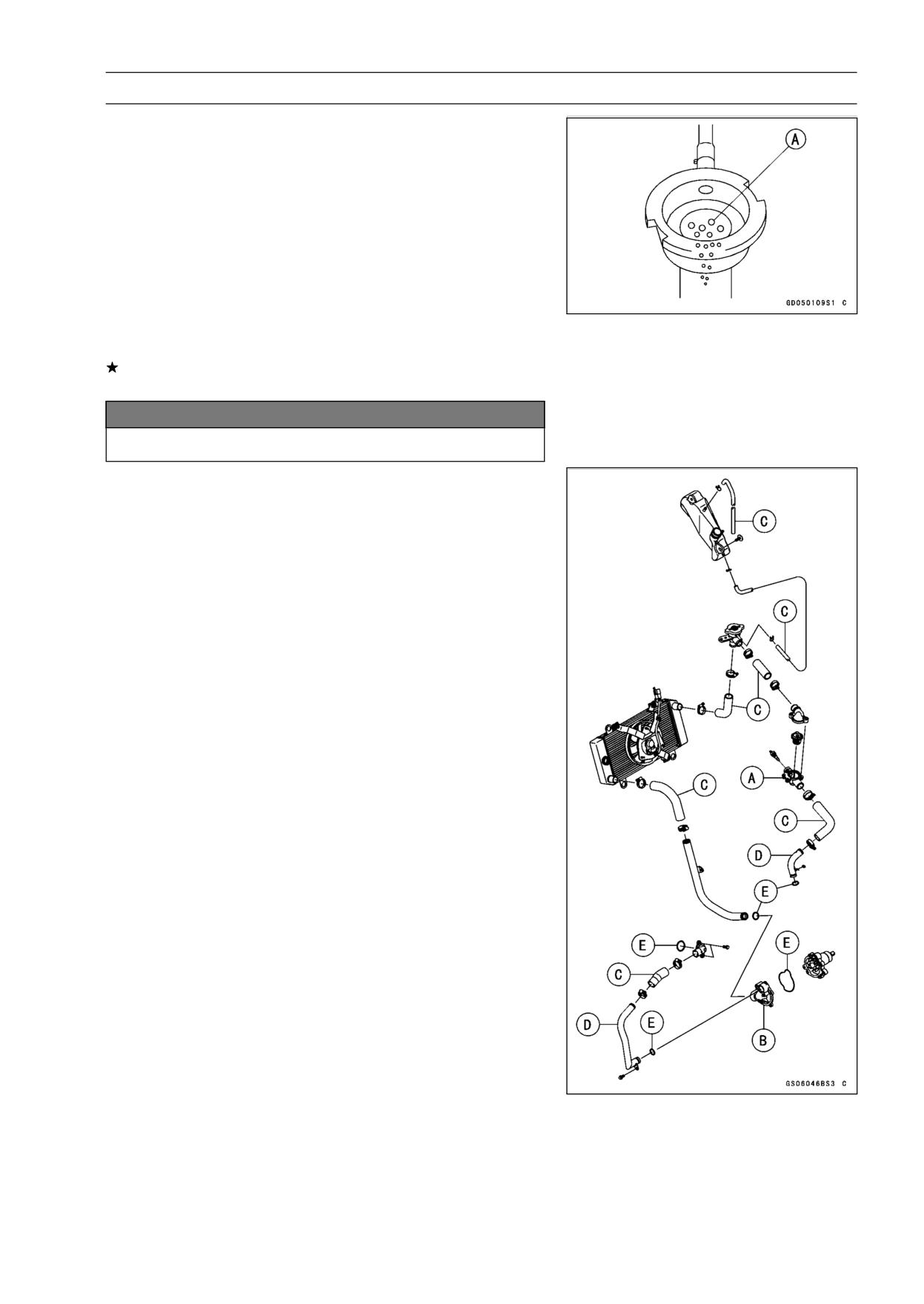
PERIODIC MAINTENANCE 2-47
Periodic Maintenance Procedures
• Bleed the air from the cooling system as follows.
○Start the engine with the radiator cap removed and run it
until no more air bubbles [A] can be seen in the coolant.
○Tap the radiator hoses to force any air bubbles caught
inside.
○Stop the engine and add coolant up to the radiator filler
neck.
• Install the radiator cap.
• Start the engine, warm it up thoroughly until the radiator
fan turns on and then stop the engine.
• Check the coolant level in the reserve tank after the en-
gine cools down.
If the coolant level is lower than the low level line, add
coolant to the full level line.
NOTICE
Do not add more coolant above the full level line.
Radiator Hose and O-ring Replacement
• Drain the coolant (see Coolant Change).
• Remove:
Thermostat Housing [A] (see Water Pump Removal in
the Cooling System chapter)
Water Pump Cover [B] (see Water Pump Removal in the
Cooling System chapter)
Hoses [C]
Pipe [D]
O-rings [E]
• Apply grease to the new O-rings and install them.
• Install the new hoses and tighten the clamps securely.
• Fill the coolant (see Coolant Change).
• Check the cooling system for leaks.
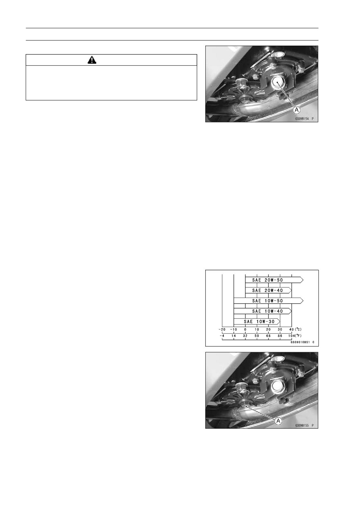
2-48 PERIODIC MAINTENANCE
Periodic Maintenance Procedures
Engine Oil Change
WARNING
The engine and exhaust system get extremely hot
during normal operation and can cause serious
burns. Never touch the engine or exhaust pipe
during oil change.
• Warm up the engine sufficiently with the motorcycle
standing on its side stand, and stop the engine.
• Place an oil pan under the engine and remove the drain
bolt [A] to drain the oil.
• Replace the drain bolt gaskets with new ones if they are
damaged.
○The oil in the oil filter can be drained by removing the filter.
• After draining the oil, tighten the drain bolts.
Torque - Oil Drain Bolts: 19.6 N·m (2.0 kgf·m, 14.5 ft·lb)
Oil Filter Mounting Bolt: 19.6 N·m (2.0 kgf·m, 14.5
ft·lb)
• Pour in the specified type and amount of oil.
Recommended Engine Oil
Type:
API SG, SH, SJ, SL or SM with JASO MA,
MA1 or MA2
Viscosity: SAE 10W - 40
Capacity:
1.3 L (1.4 US qt) (When filter is not removed)
1.6 L (1.7 US qt) (When filter is removed)
NOTE
○Do not add any chemical additive to the oil. Oils fulfilling
the above requirements are fully formulated and provide
adequate lubrication for both the engine and the clutch.
○Although 10W-40 engine oil is the recommended oil
for most conditions, the oil viscosity may need to be
changed to accommodate atmospheric conditions in
your riding area.
Oil Filter Replacement
• Drain the engine oil (see Engine Oil change).
• Remove the oil filter mounting bolt [A].
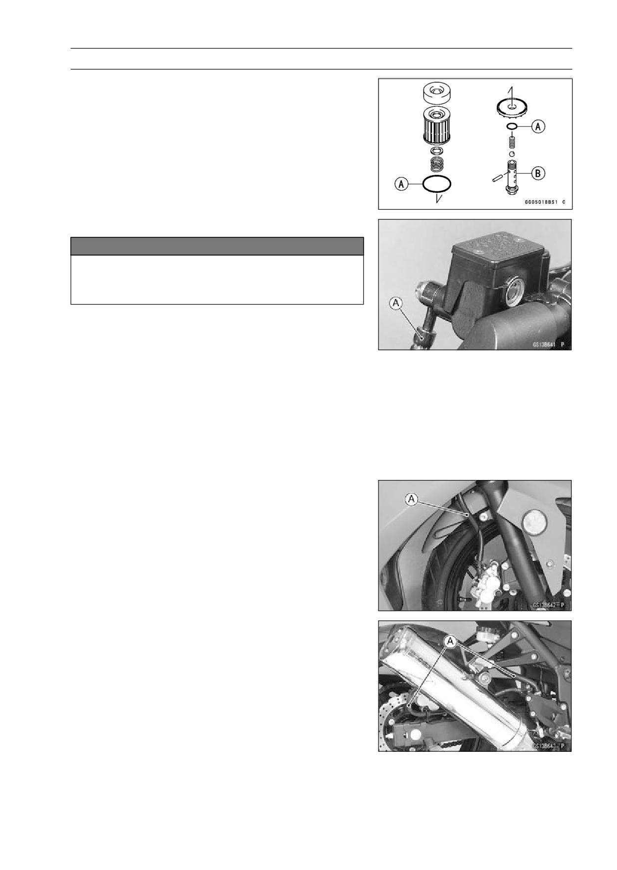
PERIODIC MAINTENANCE 2-49
Periodic Maintenance Procedures
• Replace the oil filter with a new one.
• Apply engine oil to the O-rings [A] before installation after
inspecting its damage.
• Install the oil filter mounting bolt [B] with a specified
torque.
Torque - Oil Filter Mounting Bolt: 19.6 N·m (2.0 kgf·m, 14.5
ft·lb)
• Pour in the specified type and amount of oil (see Engine
Oil Change).
Brake Hose and Pipe Replacement
NOTICE
Brake fluid quickly ruins painted plastic surfaces;
any spilled fluid should be completely washed away
immediately.
• Remove the banjo bolts.
• When removing the brake hose, take care not to spill the
brake fluid on the painted or plastic parts.
• When removing the brake hoses [A], temporarily secure
the end of the brake hose to some high place to keep fluid
loss to a minimum.
• Immediately wash away any brake fluid that spills.
• There are washers on each side of the brake hose fitting.
Replace them with new ones when installing.
• Tighten:
Torque - Brake Hose Banjo Bolts: 25 N·m (2.5 kgf·m, 18
ft·lb)
• When installing the hoses [A], avoid sharp bending, kink-
ing, flatting or twisting, and route the hoses according to
Cable, Wire, and Hose Routing section in the Appendix
chapter.
• Fill the brake line after installing the brake hose (see
Brake Fluid Change).
Brake Fluid Change
NOTE
○The procedure to change the front brake fluid is as fol-
lows. Changing the rear brake fluid is the same as for
the front brake.
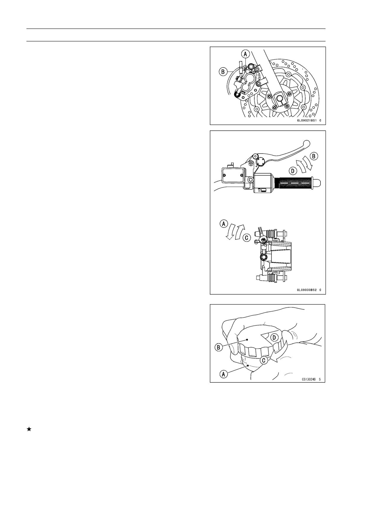
2-50 PERIODIC MAINTENANCE
Periodic Maintenance Procedures
• Level the brake fluid reservoir.
• Remove the reservoir cap and diaphragm.
• Remove the rubber cap from the bleed valve [A] on the
caliper.
• Attach a clear plastic hose [B] to the bleed valve, and run
the other end of the hose into a container.
• Fill the reservoir with fresh specified brake fluid.
• Change the brake fluid.
○Repeat this operation until fresh brake fluid comes out
from the plastic hose or the color of the fluid changes.
1. Open the bleed valve [A].
2. Apply the brake and hold it [B].
3. Close the bleed valve [C].
4. Release the brake [D].
NOTE
○The fluid level must be checked often during the chang-
ing operation and replenished with fresh brake fluid. If
the fluid in the reservoir runs out any time during the
changing operation, the brakes will need to be bled
since air will have entered the brake line.
○Front Brake: Repeat the above steps for the other
caliper.
• Remove the clear plastic hose.
• Install the diaphragm and reservoir cap.
• Tighten:
Torque - Front Brake Reservoir Cap Screws: 1.5 N·m (0.15
kgf·m, 13 in·lb)
• Follow the procedure below to install the rear brake fluid
reservoir cap correctly.
○First, tighten the rear brake fluid reservoir cap [B] clock-
wise [C] by hand until slight resistance is felt indicating
that the cap is seated on the reservoir body, then tighten
the cap an additional 1/6 turn [D] while holding the brake
fluid reservoir body [A].
• Tighten the bleed valve, and install the rubber cap.
Torque - Bleed Valve: 5.5 N·m (0.55 kgf·m, 49 in·lb)
• After changing the fluid, check the brake for good braking
power, no brake drag, and no fluid leakage.
If necessary, bleed the air from the lines.
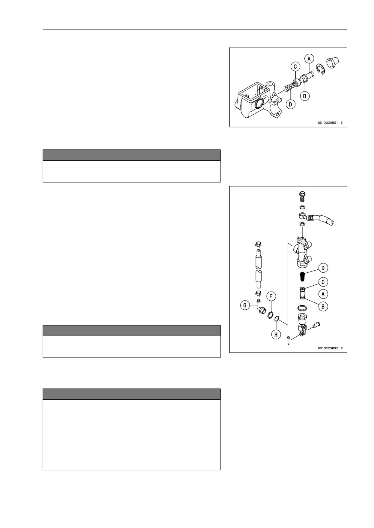
PERIODIC MAINTENANCE 2-51
Periodic Maintenance Procedures
Master Cylinder Rubber Parts Replacement
Front Master Cylinder Disassembly
• Remove the front master cylinder (see Front Master Cylin-
der Removal in the Brakes chapter).
• Remove the reservoir cap and diaphragm, and pour the
brake fluid into a container.
• Unscrew the locknut and pivot bolt, and remove the brake
lever.
• Pull the dust cover out of place, and remove the circlip.
Special Tool - Inside Circlip Pliers: 57001-143
• Pull out the piston [A], secondary cup [B], primary cup [C],
and return spring [D].
NOTICE
Do not remove the secondary cup from the piston
since removal will damage it.
Rear Master Cylinder Disassembly
NOTE
○Do not remove the push rod clevis for master cylinder
disassembly since removal requires brake position ad-
justment.
• Remove the rear master cylinder (see Rear Master Cylin-
der Removal in the Brakes chapter).
• Remove the circlip.
Special Tool - Inside Circlip Pliers: 57001-143
• Pull out the push rod with the piston stop.
• Take off the piston [A], secondary cup [B], primary cup [C]
and return spring [D].
• Remove the circlip [F] and pull out the brake hose con-
nector [G] and O-ring [H].
Special Tool - Inside Circlip Pliers: 57001-143
NOTICE
Do not remove the secondary cup from the piston
since removal will damage it.
Master Cylinder Assembly
• Before assembly, clean all parts including the master
cylinder with brake fluid or alcohol.
NOTICE
Except for the disc pads and disc, use only disc
brake fluid, isopropyl alcohol, or ethyl alcohol for
cleaning brake parts. Do not use any other fluid for
cleaning these parts. Gasoline, engine oil, or any
other petroleum distillate will cause deterioration of
the rubber parts. Oil spilled on any part will be diffi-
cult to wash off completely, and will eventually de-
teriorate the rubber used in the disc brake.
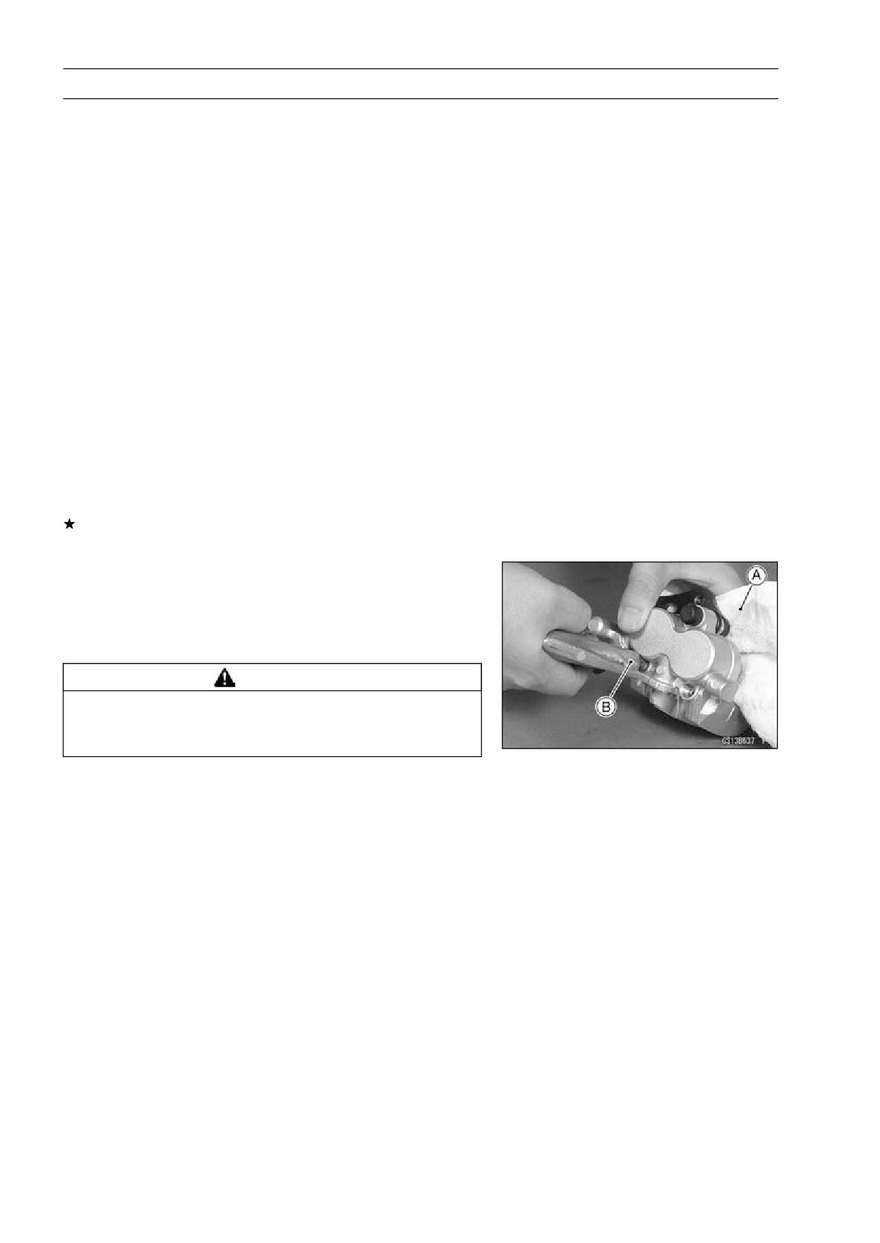
2-52 PERIODIC MAINTENANCE
Periodic Maintenance Procedures
• Apply brake fluid to the removed parts and to the inner
wall of the cylinder.
• Take care not to scratch the piston or the inner wall of the
cylinder.
• Apply silicone grease (ex. PBC grease).
Brake Lever Pivot Bolt
Brake Lever Pivot Contact
Push Rod Contact (Rear)
Dust Cover
• Tighten:
Torque - Brake Lever Pivot Bolt:
1.0 N·m (0.10 kgf·m, 9
in·lb)
Brake Lever Pivot Bolt Locknut:
5.9 N·m (0.60
kgf·m, 52 in·lb)
Caliper Rubber Parts Replacement
Caliper Disassembly
• Remove a front Caliper (see Front Caliper Removal in the
Brakes chapter).
• Remove the pads and anti-rattle spring (see Pad Removal
in the Brakes chapter).
If compressed air is available, the piston may be removed
using compressed air as follows.
• Insert the wooden board of 5 mm (0.2 in.) thick inside the
caliper opening or cover the caliper opening with a clean,
heavy cloth [A].
• Lightly apply compressed air [B] to the hose joint opening
until the pistons hit the wooden board or heavy cloth.
WARNING
The piston in the brake caliper can crush hands and
fingers. Never place your hand or fingers in front of
the piston.
• Pull out the pistons by hand.
• Immediately wipe up any brake fluid that spills. It may ruin
painted or plated surfaces.
• Remove the dust seals and fluid seals.
• Remove the bleed valve and rubber cap.
NOTE
○If compressed air is not available, do as follows for both
calipers coincidentally, with the brake hose connected
to the caliper.
○Prepare a container for brake fluid, and perform the
work above it.
○Remove the spring and pads (see Brake Pad Removal).
○Pump the brake lever or pedal until the pistons come
out of the cylinders, and then disassemble the caliper.
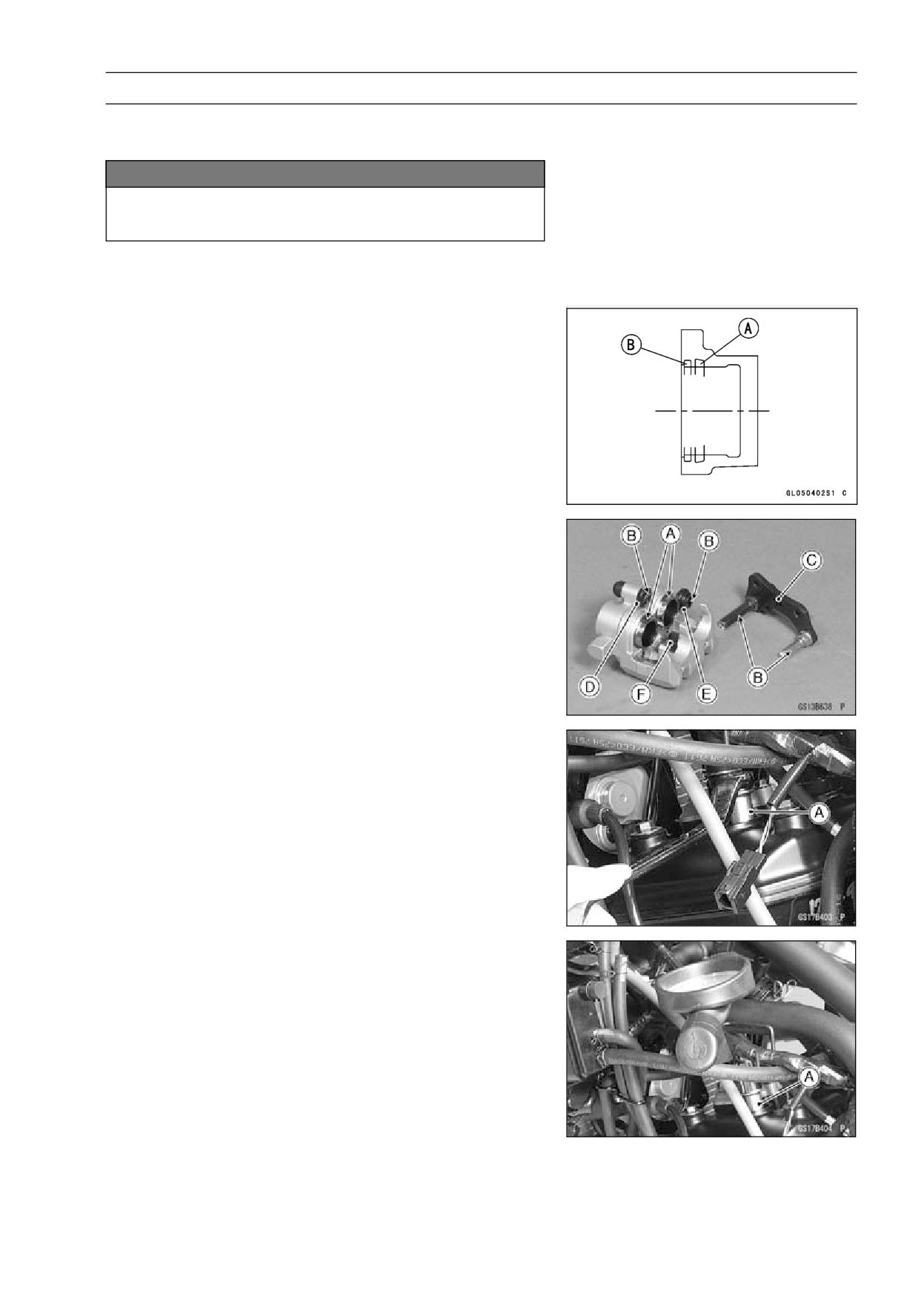
PERIODIC MAINTENANCE 2-53
Periodic Maintenance Procedures
Caliper Assembly
• Clean the caliper parts except for the pads.
NOTICE
For cleaning of the parts, use only disc brake fluid,
ispopropyl alcohol, or ethyl alcohol.
• Install the bleed valve and rubber cap.
Torque - Bleed Valve: 5.5 N·m (0.55 kgf·m, 49 in·lb)
• Replace the fluid seals [A] and dust seals [B] with new
one.
• Apply brake fluid to the fluid seals and dust seals, and
install them into the cylinder by hand.
• Apply brake fluid [A] to the outside of the pistons and push
them into each cylinder by hand without scratching the
cylinder and piston skirt.
• Apply silicone grease [B] to the caliper holder shaft and
holder holes, and install the caliper holder [C], rubber boot
[D] and dust cover [E].
• Install the anti-rattle spring [F] and pads in the caliper (see
Pad Installation in the Brakes chapter).
Spark Plug Replacement
• Remove:
Spark Plugs (see Spark Plug Removal in the Electrical
System chapter)
• Remove the spark plugs using the 16 mm plug wrench
[A].
Owner’s Tool - Spark Plug Wrench, 16 mm: 92110-0044
• Insert the spark plug vertically into the plug hole with the
spark plug installed in the plug wrench [A].
Owner’s Tool - Spark Plug Wrench, 16 mm: 92110-0044
• Tighten:
Torque - Spark Plugs: 13 N·m (1.3 kgf·m, 115 in·lb)
• Install:
Spark Plugs (see Spark Plug Installation in the Electrical
System chapter)
FUEL SYSTEM 3-1
Fuel System
Table of Contents
Exploded View
3-3
Exploded View (EX250J8)
3-8
Exploded View (EX250J9 ∼ JC)
3-10
Specifications
3-12
3
Special Tools
3-13
Throttle Grip and Cables
3-14
Free Play Inspection
3-14
Free Play Adjustment
3-14
Throttle Cable Removal
3-14
Throttle Cable Installation
3-14
Throttle Cable Lubrication
3-14
Choke Cable
3-15
Free Play Inspection
3-15
Free Play Adjustment
3-15
Choke Cable Removal
3-15
Choke Cable Installation
3-15
Choke Cable Lubrication and Inspection
3-15
Carburetors
3-16
Idle Speed Inspection
3-16
Idle Speed Adjustment
3-16
Engine Vacuum Synchronization Inspection
3-16
Engine Vacuum Synchronization Adjustment
3-16
Pilot Screw Adjustment
3-16
Service Fuel Level Inspection
3-17
Service Fuel Level Adjustment
3-18
Fuel System Cleanliness Inspection
3-19
Carburetor Removal
3-20
Carburetor Installation
3-21
Carburetor Separation
3-21
Carburetor Joining
3-21
Carburetor Disassembly
3-23
Carburetor Assembly
3-23
Carburetor Cleaning
3-24
Carburetor Inspection
3-25
Air Cleaner
3-27
Air Cleaner Element Removal
3-27
Air Cleaner Element Installation
3-27
Air Cleaner Housing Removal
3-27
Air Cleaner Housing Installation
3-28
Air Cleaner Housing Disassembly
3-28
Air Cleaner Housing Assembly
3-28
Oil Draining
3-29
Fuel Tank
3-30
Fuel Tank Removal
3-30
Fuel Tank Installation
3-30
Fuel Tap Removal
3-31
Fuel Tap Installation
3-31
Fuel Tank and Tap Cleaning
3-31
Fuel Tap Inspection
3-32
Fuel Tank and Cap Inspection
3-32
3-2 FUEL SYSTEM
Evaporative Emission Control System (CAL Model)
3-33
Separator Operation Test
3-33
Canister Inspection
3-33
Parts Removal/Installation
3-33
Hose Inspection
3-33
FUEL SYSTEM 3-3
Exploded View
This page intentionally left blank.
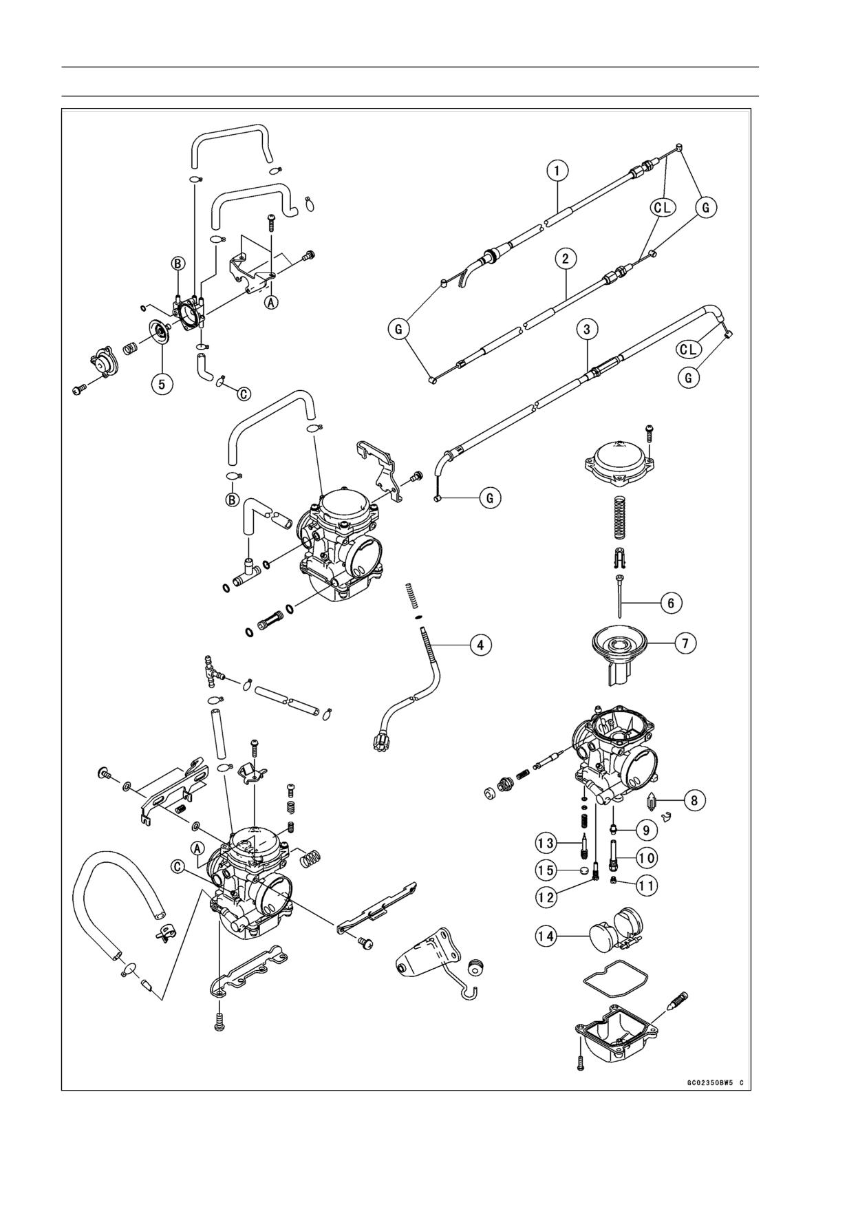
3-4 FUEL SYSTEM
Exploded View
FUEL SYSTEM 3-5
Exploded View
1. Throttle Cable (accelerator)
2. Throttle Cable (decelerator)
3. Choke Cable
4. Idle Adjusting Screw
5. Air Cut Valve
6. Jet Needle
7. Vacuum Valve
8. Float Valve
9. Needle Jet
10. Needle Jet Holder
11. Main Jet
12. Pilot Jet
13. Pilot Air Screw
14. Float
15. Plug
CL: Apply cable lubricant.
G: Apply grease.
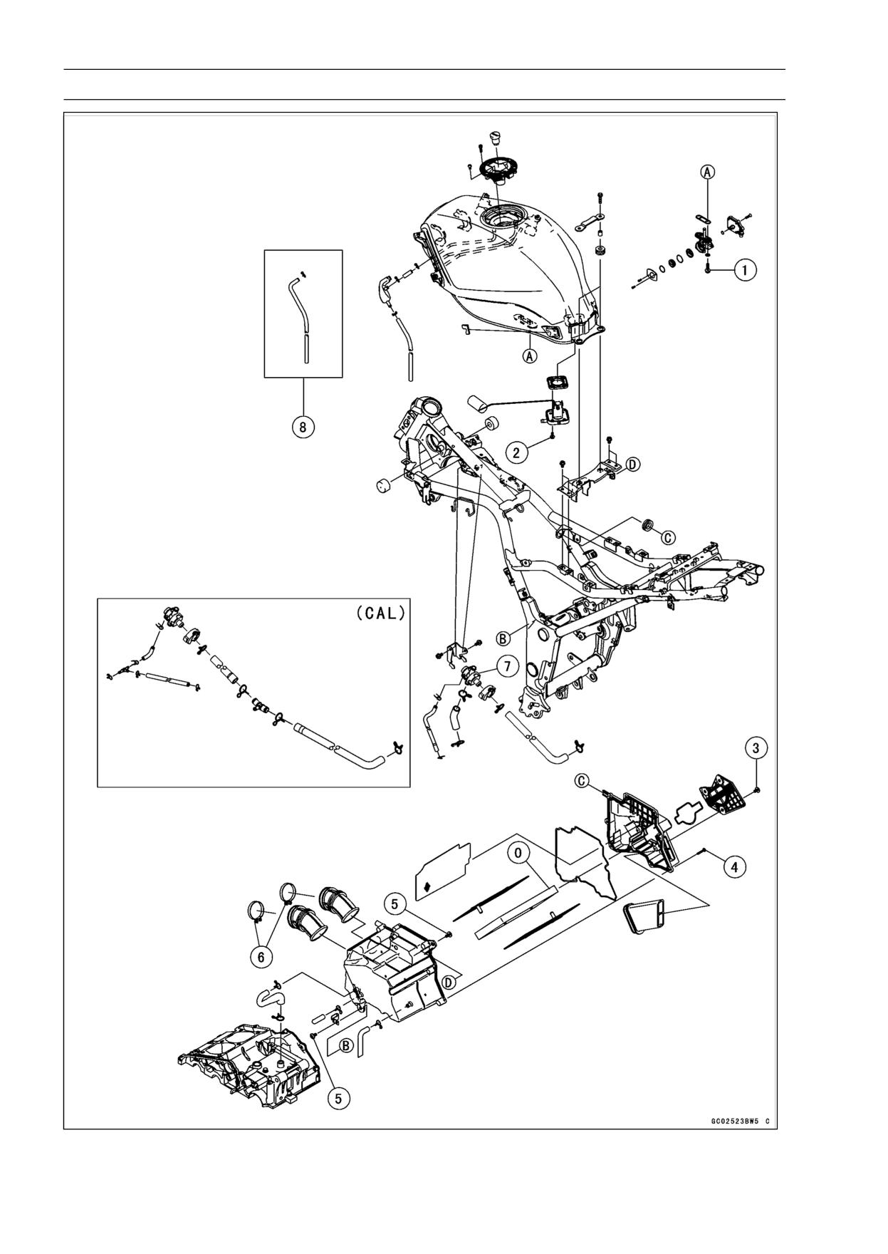
3-6 FUEL SYSTEM
Exploded View

FUEL SYSTEM 3-7
Exploded View
Torque
No.
Fastener
Remarks
N·m
kgf·m
ft·lb
1
Fuel Tap Mounting Bolts
2.5
0.25
22 in·lb
2
Fuel Gauge Mounting Bolts
6.9
0.7
61 in·lb
3
Air Cleaner Housing Cap Bolts/Screws
2.5
0.25
22 in·lb
4
Air Cleaner Housing Screws
1.15
0.12
10 in·lb
5
Air Cleaner Housing Mounting Bolts
9.8
1.0
87 in·lb
6
Air Cleaner Housing Clamp Screws
2.0
0.2
18 in·lb
7. Vacuum Switch Valve
8. EX250J8 ∼ JA, EX250JB ∼ JC (CAL Model)
O: Apply high-quality foam air filter oil.
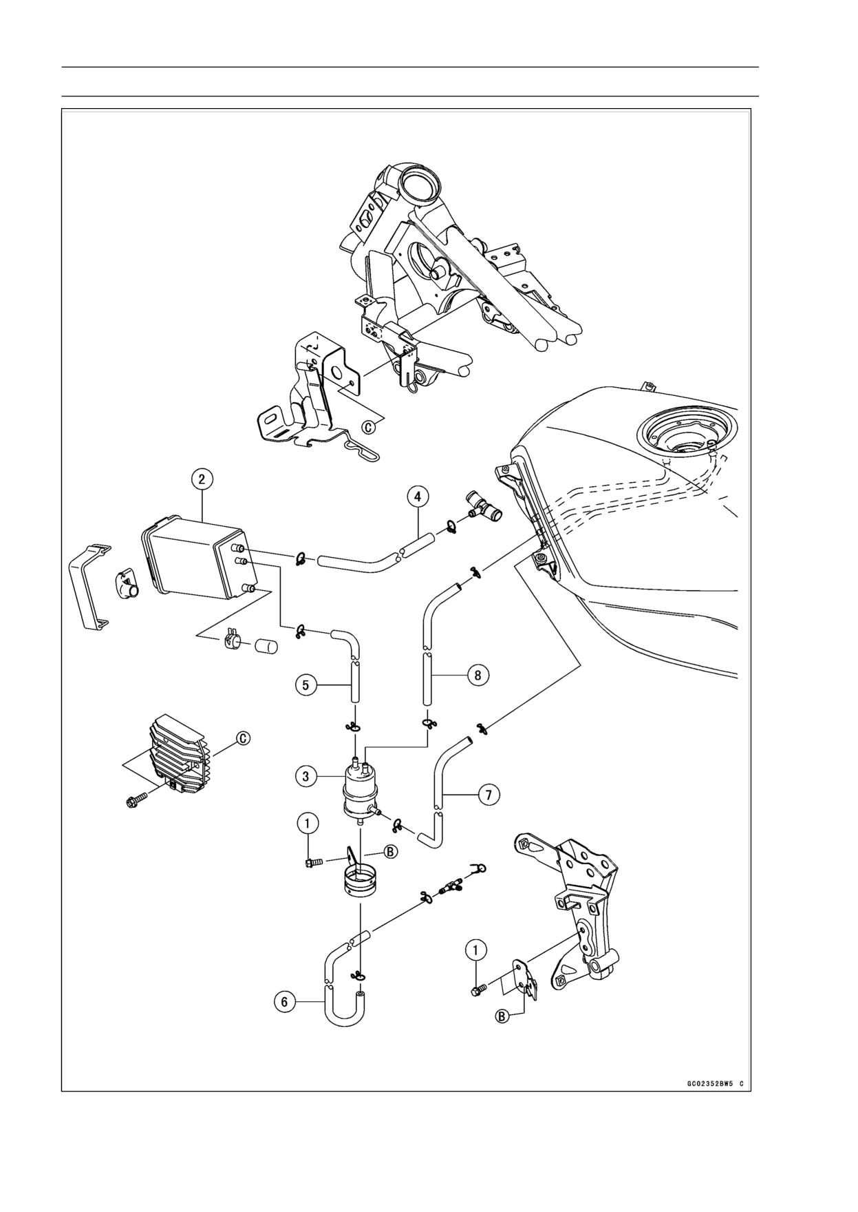
3-8 FUEL SYSTEM
Exploded View (EX250J8)
FUEL SYSTEM 3-9
Exploded View (EX250J8)
Torque
No.
Fastener
Remarks
N·m
kgf·m
ft·lb
1
Separate Bracket Bolt
9.8
1.0
87 in·lb
2. Canister
3. Separator
4. Green Hose
5. Blue Hose
6. White Hose
7. Red Hose
8. Blue Hose
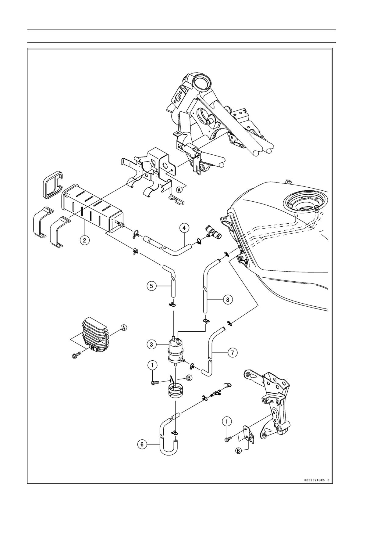
3-10 FUEL SYSTEM
Exploded View (EX250J9 ∼ JC)
FUEL SYSTEM 3-11
Exploded View (EX250J9 ∼ JC)
Torque
No.
Fastener
Remarks
N·m
kgf·m
ft·lb
1
Separate Bracket Bolt
9.8
1.0
87 in·lb
2. Canister
3. Separator
4. Green Hose
5. Blue Hose
6. White Hose
7. Red Hose
8. Blue Hose
3-12 FUEL SYSTEM
Specifications
Item
Standard
Throttle Grip and Cable
Throttle Grip Free Play
2 ∼ 3 mm (0.08 ∼ 0.12 in.)
Choke Cable Free Play
2 ∼ 3 mm (0.08 ∼ 0.12 in.)
Carburetor
Make, Type
Keihin, CVK30
Main Jet
#98
Optional Main Jet
#92, 95, 100, 102
Main Air Jet
#100
Jet Needle
#L: N9VU, #R: N9VW
Needle Jet
#6
Pilot Jet
#38
Pilot Air Jet
#100
Starter Jet
#48
Pilot Screw (turns out)
#L: 2 1/2, #R: 1 3/4
Throttle Valve
11° 00’
Idle Speed
1 300 ±50 r/min (rpm)
Carburetor Synchronization Vacuum
Less than 2.7 kPa (2 cmHg) difference between two
carburetors.
Service Fuel Level
0.5 ±1 mm (0.02 ±0.04 in.) above the mating surface of
carburetor float bowl.
Float Height
17 ±2 mm (0.67 ±0.08 in.)
Air Cleaner Element
Type
Polyurethane foam
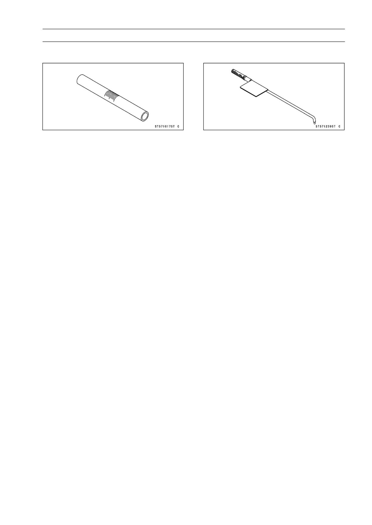
FUEL SYSTEM 3-13
Special Tools
Fuel Level Gauge:
Pilot Screw Adjuster, A:
57001-1017
57001-1239

3-14 FUEL SYSTEM
Throttle Grip and Cables
Free Play Inspection
• Refer to Throttle Control System Inspection in the Peri-
odic Maintenance chapter (see Throttle Control System
Inspection in the Periodic Maintenance chapter).
Free Play Adjustment
• Refer to Throttle Control System Inspection in the Peri-
odic Maintenance chapter (see Throttle Control System
Inspection in the Periodic Maintenance chapter).
Throttle Cable Removal
• Split the right handlebar switch housing [A] removing the
screws [B], and remove the throttle cable upper ends from
the throttle grip.
• Remove:
Front Seat (see Front Seat Removal in the Frame chap-
ter)
Side Cover (see Side Cover Removal in the Frame chap-
ter)
Right Lower Fairing (see Lower Fairing Removal in the
Frame chapter)
• Loosen the locknuts [A] and remove the lower end of the
accelerator cable [B] from the pulley.
• Loosen the locknuts [C] and remove the lower end of the
decelerator cable [D] from the pulley.
• Pull out the throttle cables upward
Throttle Cable Installation
• Install the throttle cables in accordance with the Cable,
Wire and Hose Routing in the Appendix chapter.
• Install the accelerator cable first and then decelerator ca-
ble.
• After installation, adjust each cable properly (see Throttle
Cable Inspection in the Periodic Maintenance chapter).
WARNING
Operation with incorrectly routed or improperly ad-
justed cables could result in an unsafe riding con-
dition. Be sure the cables are routed correctly and
properly adjusted.
Throttle Cable Lubrication
• Refer to Chassis Parts Lubrication Perform in the Peri-
odic Maintenance chapter (see Chassis Parts Lubrication
Perform in the Periodic Maintenance chapter).
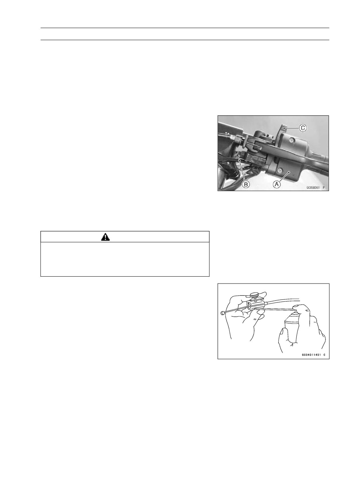
FUEL SYSTEM 3-15
Choke Cable
Free Play Inspection
• Refer to Choke Operation Inspection in the Periodic Main-
tenance chapter (see Choke Operation in the Periodic
Maintenance chapter).
Free Play Adjustment
• Refer to Choke Operation Inspection in the Periodic Main-
tenance chapter (see Choke Operation in the Periodic
Maintenance chapter).
Choke Cable Removal
• Split the left handlebar switch housing [A], and remove
the choke cable [B] upper end from the choke lever [C].
• Remove:
Front Seat (see Front Seat Removal in the Frame chap-
ter)
Fuel Tank (see Fuel Tank Removal)
• Remove the choke cable end from the cable bracket of
carburetor.
• Pull out the choke cable upward.
Choke Cable Installation
• Install the choke cable in accordance with the Cable,
Wire, and Hose Routing section in Appendix chapter.
• After installation, adjust the cable properly.
WARNING
Operation with incorrectly routed or improperly ad-
justed cable could result in an unsafe riding condi-
tion. Be sure the cable is routed correctly and prop-
erly adjusted.
Choke Cable Lubrication and Inspection
• Whenever the cable is removed, or in accordance with
the Periodic Maintenance Chart, lubricate the choke cable
(see General Lubrication in the Appendix chapter).
○Apply a thin coating of grease to the cable lower end.
○Use a commercially available pressure cable lubricator to
lubricate the cable.
○With the cable disconnected at both ends, the cable
should move freely in the cable housing.
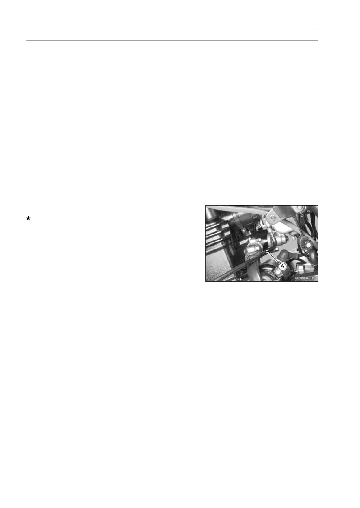
3-16 FUEL SYSTEM
Carburetors
Idle Speed Inspection
• Refer to Idle Speed Inspection in the Periodic Mainte-
nance chapter (see Idle Speed Inspection in the Periodic
Maintenance chapter).
Idle Speed Adjustment
• Refer to Idle Speed Adjustment in the Periodic Mainte-
nance chapter (see Idle Speed Adjustment in the Periodic
Maintenance chapter).
Engine Vacuum Synchronization Inspection
• Refer to Engine Vacuum Synchronization Inspection in
the Periodic Maintenance chapter (see Engine Vacuum
Synchronization Inspection in the Periodic Maintenance
chapter).
Engine Vacuum Synchronization Adjustment
• Refer to Engine Vacuum Synchronization Inspection in
the Periodic Maintenance chapter (see Engine Vacuum
Synchronization Inspection in the Periodic Maintenance
chapter).
Pilot Screw Adjustment
If the engine idle is still not stable, adjust the pilot screw to
obtain the proper idle speed using the pilot screw adjuster
[A].
Special Tool - Pilot Screw Adjuster: 57001-1239
○Turn in the pilot screw fully but not tightly, and then back
it out the specified turns. To set the screw to its original
position.
Pilot Screw Setting:
#L: 2 1/2
#R: 1 3/4
NOTE
○The standard number of turns the pilot screw must be
backed out varies by carburetor. The values given in the
specifications should be used only when the number of
the original back out turns is unavailable.
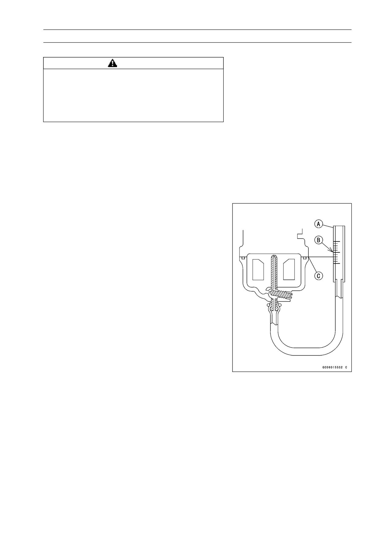
FUEL SYSTEM 3-17
Carburetors
Service Fuel Level Inspection
WARNING
Gasoline is extremely flammable and can be ex-
plosive under certain conditions. Turn the ignition
switch OFF. Do not smoke. Make sure the area is
well-ventilated and free from any source of flame
or sparks; this includes any appliance with a pilot
light.
• Situate the motorcycle so that it is perpendicular to the
ground.
• Remove:
Front Seat (see Front Seat Removal in the Frame chap-
ter)
Fuel Tank (see Fuel Tank Removal)
• Prepare an auxiliary fuel tank and connect the fuel hose
to the carburetor.
• Prepare a fuel hose.
• Connect the fuel level gauge [A] to the carburetor float
bowl with the fuel hose.
Special Tool - Fuel Level Gauge: 57001-1017
• Hold the gauge vertically against the side of the carburetor
body so that the “middle” line [B] is several millimeters
higher than the mating surface [C] of the carburetor float
bowl.
• Feed fuel to the carburetor, then turn the carburetor drain
plug out a few turns.
• Wait until the fuel level in the gauge settles.
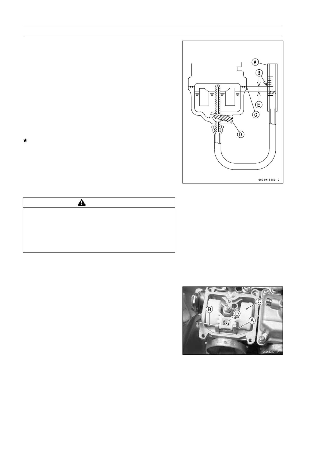
3-18 FUEL SYSTEM
Carburetors
• Keeping the gauge vertical, align the “middle” line with the
mating surface.
NOTE
○Do not lower the “middle” line below the mating surface
of the carburetor float bowl. If the gauge is lowered
and then raised again, the fuel level measured shows
somewhat higher than the actual fuel level. If the gauge
is lowered too far, dump the fuel out of it into a suitable
container and start the procedure over again.
• Read the fuel level [E] in the gauge and compare to the
specification.
• Screw in the carburetor drain plug [D].
• Stop feeding and remove the fuel level gauge.
If the fuel level is incorrect, adjust it (see Service Fuel
Level Adjustment).
Service Fuel Level (above the mating surface of carburetor
float bowl)
Standard:
0.5 mm ±1 mm (0.02 ±0.04 in.)
Service Fuel Level Adjustment
WARNING
Gasoline is extremely flammable and can be ex-
plosive under certain conditions. Turn the ignition
switch OFF. Do not smoke. Make sure the area is
well-ventilated and free from any source of flame
or sparks; this includes any appliance with a pilot
light.
• Remove the carburetor, and drain the fuel into a suitable
container.
• Remove the fittings with water hose.
• Remove the float bowl.
• Slide out the pivot pin [A] with a suitable tool [B], and
remove the float [C] and float valve needle [D].
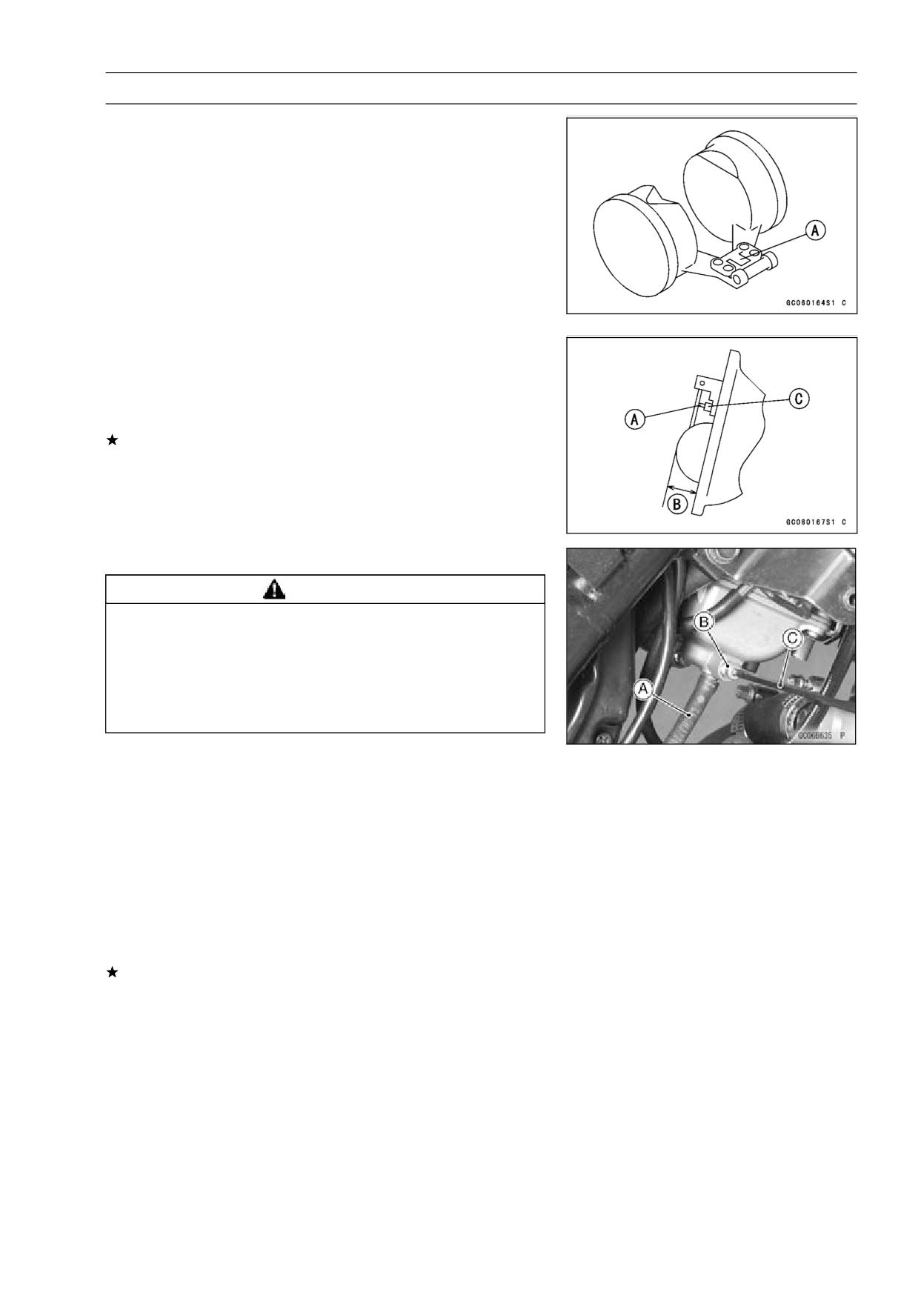
FUEL SYSTEM 3-19
Carburetors
• Bend the tang [A] on the float arm very slightly to change
the float height. Increasing the float height lowers the fuel
level and decreasing the float height raises the fuel level.
Float height
Standard:
17 ±2 mm (0.67 ±0.08 in.)
NOTE
○Do not push the needle rod [A] in during the float height
measurement [B].
• Assemble the carburetor, and recheck the fuel level.
If the fuel level cannot be adjusted by this method, the
float or the float valve [C] is damaged.
Fuel System Cleanliness Inspection
WARNING
Gasoline is extremely flammable and can be ex-
plosive under certain conditions. Turn the ignition
switch OFF. Do not smoke. Make sure the area is
well-ventilated and free from any source of flame
or sparks; this includes any appliance with a pilot
light.
• Remove:
Right Lower Fairing (see Lower Fairing Removal in the
Frame chapter)
• Connect a suitable hose [A] to the fitting at the bottom of
each carburetor float bowl.
• Run the lower end of the carburetor drain hose into a suit-
able container.
• Turn out each drain plug [B] a few turns and drain the float
bowls with a hexagon wrench [C].
• Check to see if water or dirt comes out.
• Tighten the drain plug.
If any water or dirt appears during the above inspection,
clean the fuel system (see Carburetor Cleaning and Fuel
Tank Cleaning).
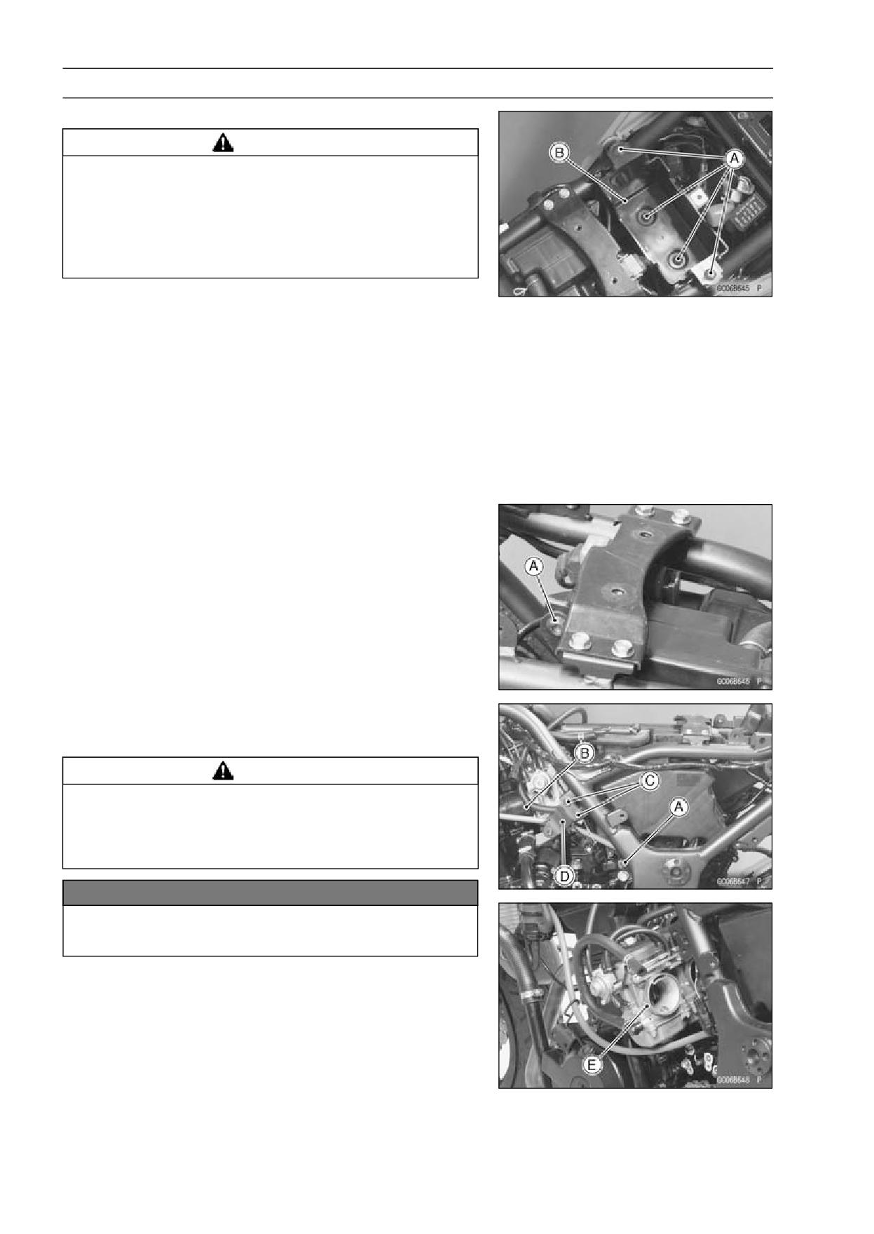
3-20 FUEL SYSTEM
Carburetors
Carburetor Removal
WARNING
Gasoline is extremely flammable and can be ex-
plosive under certain conditions. Turn the ignition
switch OFF. Do not smoke. Make sure the area is
well-ventilated and free from any source of flame
or sparks; this includes any appliance with a pilot
light.
• Remove:
Front Seat (see Front Seat Removal in the Frame chap-
ter)
Fuel Tank (see Fuel Tank Removal)
Lower Fairings (see Lower Fairing Removal in the Frame
chapter)
Battery (see Battery Removal in the Electrical System
chapter)
Battery Damper
Battery Case Screws [A]
Battery Case [B]
• Remove the air cleaner housing mounting bolts [A].
• Loosen the carburetor holder clamps [B] off the air cleaner
ducts.
• Pull the air cleaner housing rearward.
• Remove the throttle cable and choke cable (see Throttle
Cable and Choke Cable Removal)
• Remove:
Bolts [C]
Bracket [D]
Carburetor [E]
• Stuff the pieces of lint-free, clean cloths into the carbure-
tor holder and the air cleaner duct to keep dirt out of the
engine and air cleaner.
WARNING
If dirt or dust is allowed to pass through into the
carburetor, the throttle may become stuck, possibly
causing accident. Replace the air cleaner element
according to the maintenance chart.
NOTICE
If dirt gets through into the engine, excessive en-
gine wear and possibly engine damage will occur.
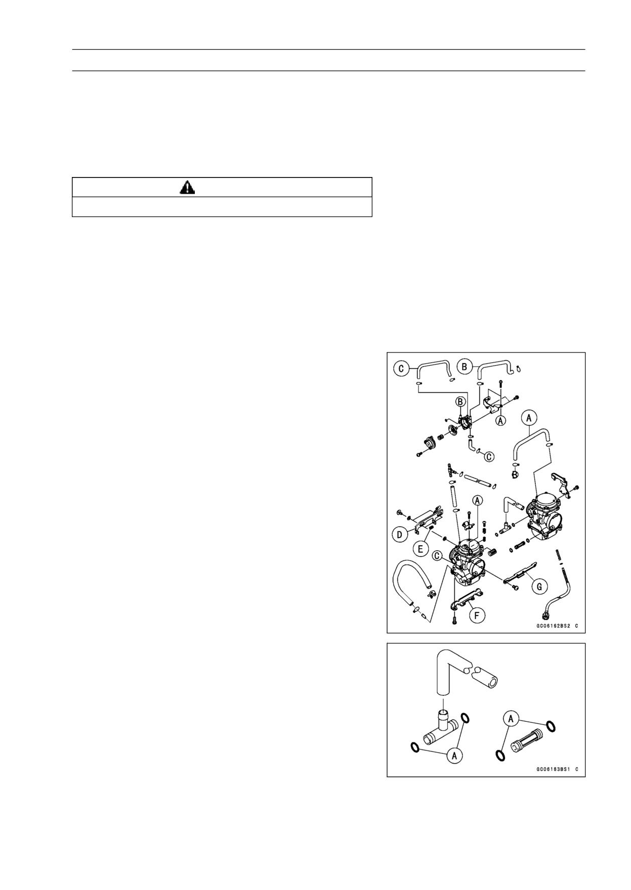
FUEL SYSTEM 3-21
Carburetors
Carburetor Installation
• Route the cables, harness, and hoses correctly (see Ca-
ble, Wire and Hose Routing section in the Appendix chap-
ter).
• Tighten the clamps for the carburetor holders and slide
back the spring bands for the air cleaner housing securely.
• Check fuel leakage from the carburetor.
WARNING
Fuel spilled from the carburetor is hazardous.
• Adjust the following items if necessary.
Idle Speed (see Idle Speed Adjustment in the Periodic
Maintenance chapter)
Carburetor Synchronization (see Carburetor Synchro-
nization Adjustment in the Periodic Maintenance chap-
ter)
Throttle Cable (see Throttle Control System Inspection
in the Periodic Maintenance chapter)
Choke Cable
Carburetor Separation
• Remove the carburetor (see Carburetor Removal).
• Pull out the air cut valve hoses [A], [B], [C] of the air cut
valve.
• Remove the choke plunger lever [D], spring [E] and car-
buretor mounting plates [F], [G].
• Gently, separately the carburetors each other.
Carburetor Joining
• When installing the carburetor, check to see that the O
-rings [A] are in place.
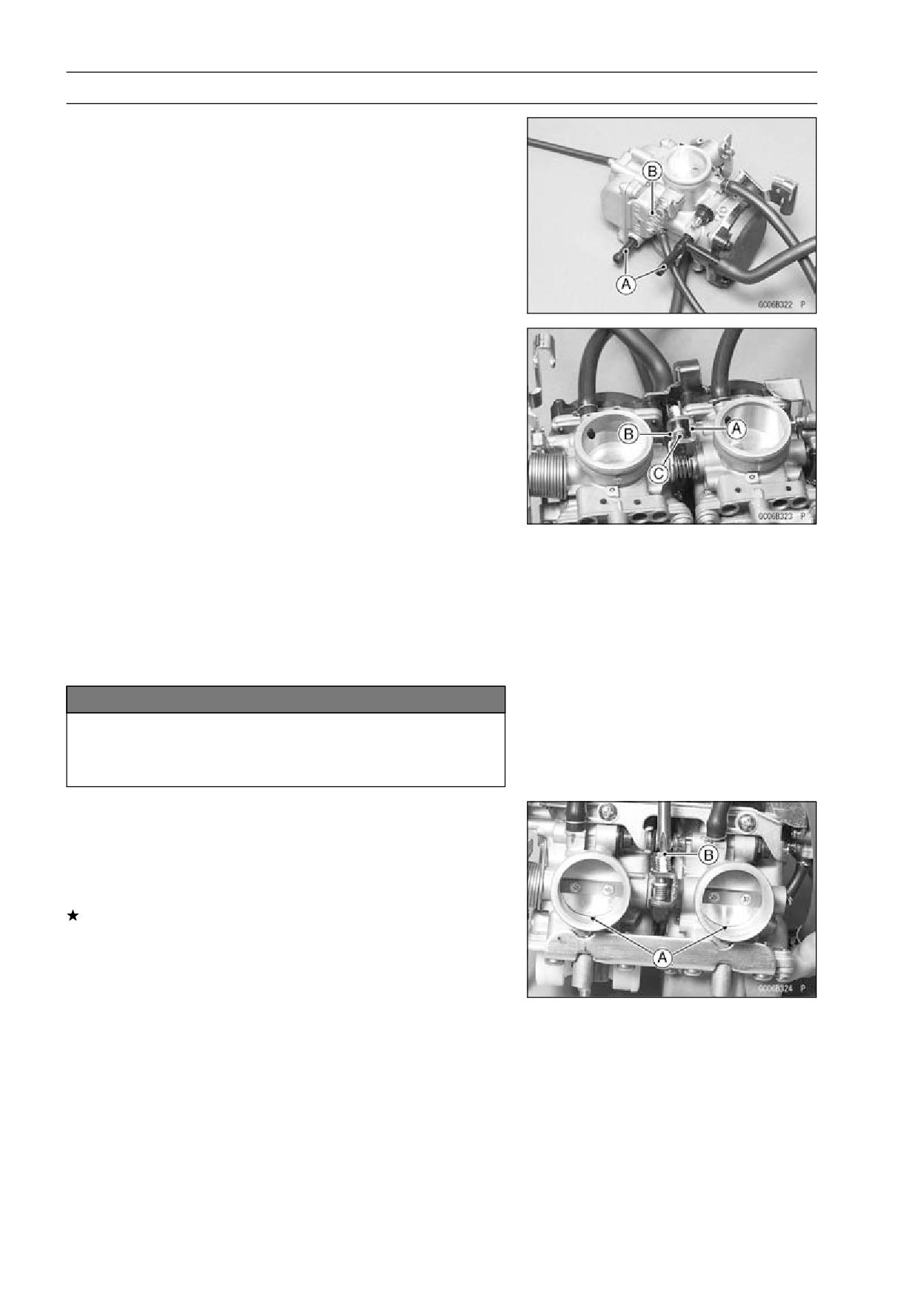
3-22 FUEL SYSTEM
Carburetors
• Install the fitting [A] and spring [B] as shown.
• Install the connecting plates [A] [B] and spring [C] as
shown.
• The center lines of the carburetor bores must be parallel
both horizontally and vertically. If they are not, loosen
the mounting screws and align the carburetors on a flat
surface. Retighten the mounting screws.
• After installing the choke mechanism, check to see that
the choke plunger lever slides right to left smoothly with-
out abnormal friction.
NOTICE
Fuel mixture trouble could result if the choke
plunger does not seat properly in its rest position
after the choke lever is returned.
• Visually synchronize the throttle (butterfly) valves.
○Check to see that all throttle valves open and close
smoothly without binding when turning the pulley.
○Visually check the clearance [A] between the throttle
valve and the carburetor bore in each carburetor.
If there is a difference between two carburetors, turn the
balance adjusting screw [B] to obtain the same clearance.
• Install the carburetors (see Carburetor Installation).
• Adjust the synchronization (see Carburetor Synchroniza-
tion Adjustment in the Periodic Maintenance Chapter).
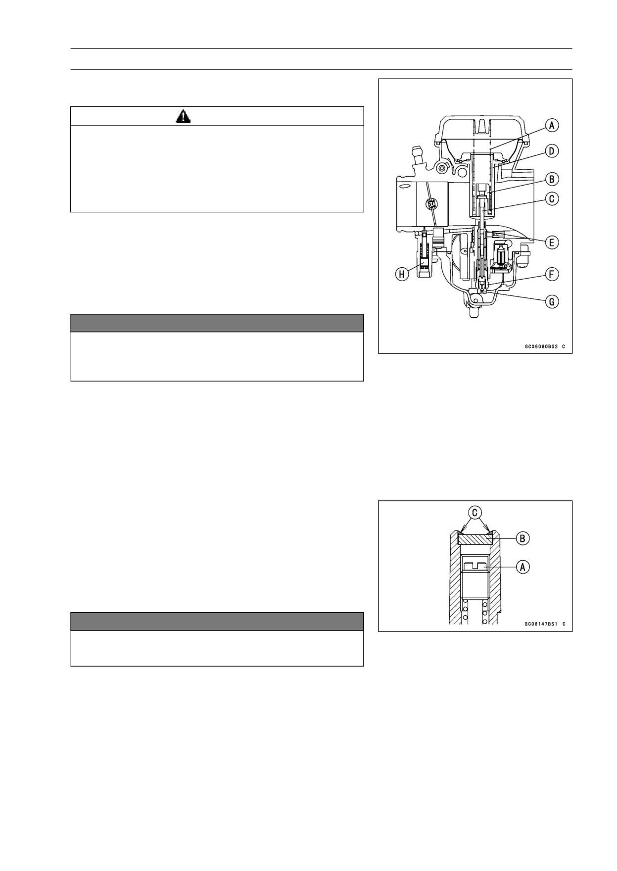
FUEL SYSTEM 3-23
Carburetors
Carburetor Disassembly
• Remove the carburetors (see Carburetor Removal).
WARNING
Gasoline is extremely flammable and can be ex-
plosive under certain conditions. Turn the ignition
switch OFF. Do not smoke. Make sure the area is
well-ventilated and free from any source of flame
or sparks; this includes any appliance with a pilot
light.
• For the Canada model, remove the pilot screw plug as
follows: punch a hole in the plug and pry there with an
awl or other suitable tool.
• Turn in the pilot screw and count the number of turns until
it seats fully but not tightly, and then remove the screw.
This is to set the screw to its original position when as-
sembling.
NOTICE
During carburetor disassembly, be careful not to
damage the diaphragm. Never use a sharp edge to
remove the diaphragm.
• Remove:
Spring [A]
Spring Seat [B]
Jet Needle [C]
Vacuum Piston [D]
Needle Jet [E]
Needle Jet Holder [F] and Main Jet [G]
Pilot Screw [H]
Carburetor Assembly
• Turn in the pilot screw [A] fully but not tightly, and then
back it out the same number of turns counted during dis-
assembly.
• Install the pilot screw plug as follows: install a new plug [B]
in the pilot screw hole of the carburetor body, and apply a
small amount of a bonding agent [C] to the circumference
of the plug to fix the plug.
NOTICE
Do not apply too much bonding agent to the plug or
the pilot screw itself may be fixed.
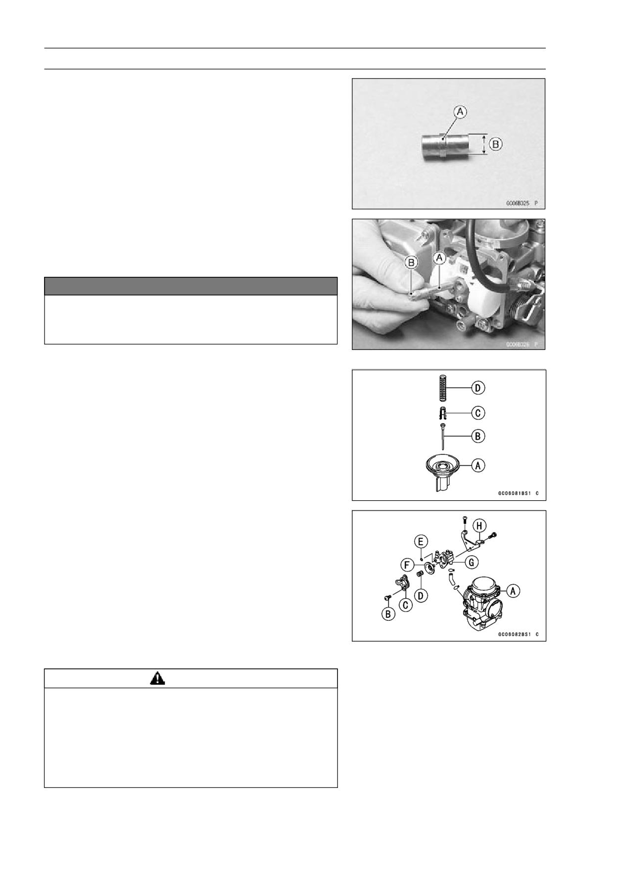
3-24 FUEL SYSTEM
Carburetors
• To install the needle jet [A], turn the carburetor body up
-side down, and drop the needle jet into place so that the
smaller diameter end [B] of the jet goes in first.
• Carefully screw in the needle jet holder [A]. It will seat
against the needle jet, pushing the end of the jet into the
carburetor bore.
Main Jet [B]
NOTICE
Do not apply force to the jet or overtighten it, as
this could damage the jet or the carburetor body,
requiring replacement.
• Install the float bowl.
• Slip the jet needle [B] through the hole in the center of
the vacuum piston, and put the spring seat [C] on the top
of the needle. Turn the seat so that it does not block the
hole at the bottom of the vacuum piston [A].
Spring [D]
• Install the carburetor top cover.
• Turn in the pilot screw fully but not tightly, and then back it
out the same number of turns counted during disassem-
bly.
• When removing the air cut valve assembly, unscrew the
mounting screws [B] and remove the cover [C], spring [D],
O-ring [E] and diaphragm [F].
• Install:
Left Carburetor [A]
Air Cut Valve Body [G]
Air Cut Valve Mounting Plate [H]
Carburetor Cleaning
WARNING
Gasoline and low-flash point solvents can be
flammable and/or explosive and cause severe
burns. Clean the carburetor in a well ventilated
area, and take care that there are no sparks or flame
anywhere near the working area; this includes any
appliance with a pilot light. Do not use gasoline or
a low-flash point solvent to clean the carburetor.
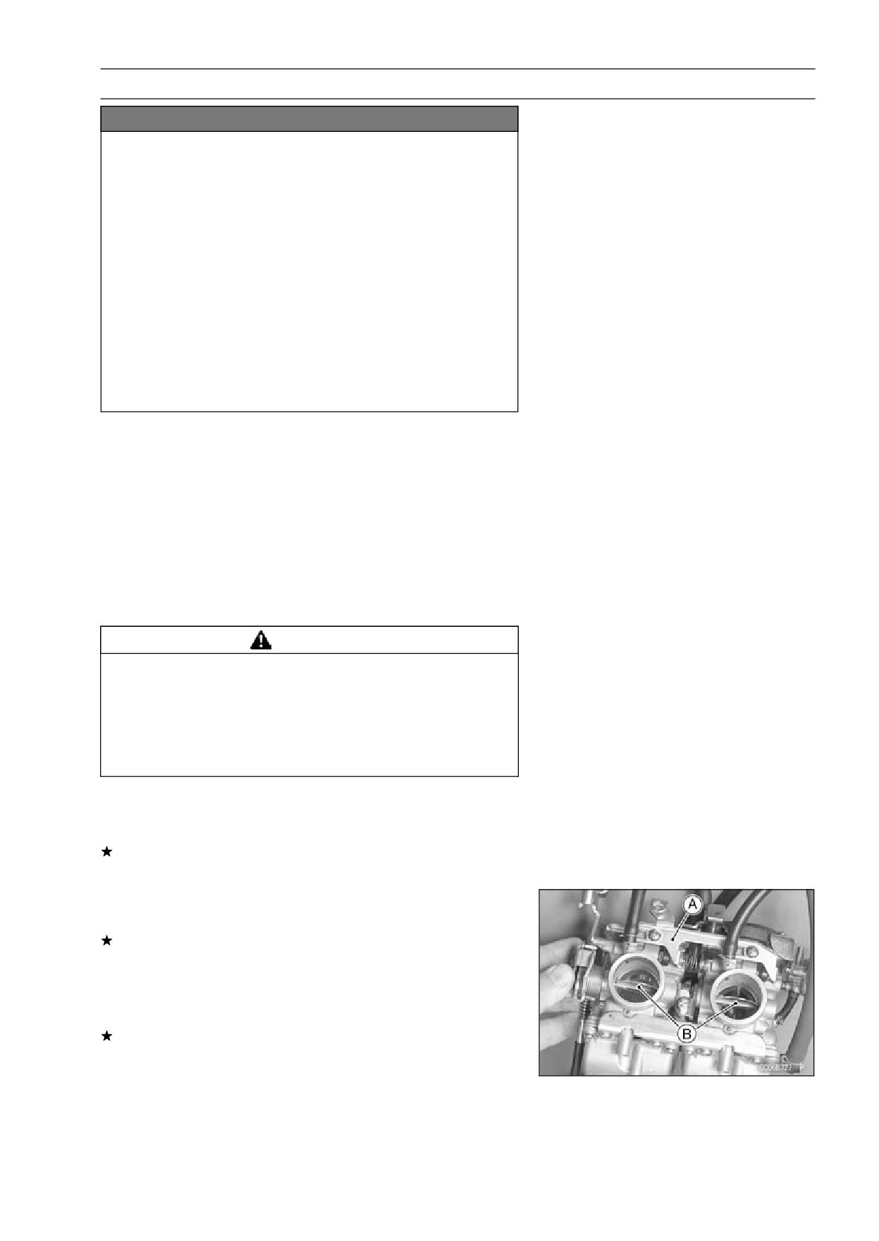
FUEL SYSTEM 3-25
Carburetors
NOTICE
Do not use compressed air on an assembled carbu-
retor, or the floats may be crushed by the pressure,
and the vacuum piston diaphragm may be dam-
aged. Remove as many rubber or plastic parts
from the carburetor as possible before cleaning the
carburetor with a cleaning solution. This will pre-
vent damage to or deterioration of the parts. The
carburetor body has plastic parts that cannot be
removed. Do not use a strong carburetor cleaning
solution which could attack these parts; instead,
use a mild high-flash point cleaning solution safe
for plastic parts. Do not use wire or any other hard
instrument to clean carburetor parts, especially
jets, as they may be damaged.
• Disassemble the carburetor (see Carburetor Disassem-
bly).
• Immerse all the metal parts in a carburetor cleaning solu-
tion.
• Rinse the parts in water.
• When the parts are clean, dry them with compressed air.
• Blow through the air and fuel passages with compressed
air.
• Assemble the carburetor (see Carburetor Assembly).
Carburetor Inspection
WARNING
Gasoline is extremely flammable and can be ex-
plosive under certain conditions. Turn the ignition
switch OFF. Do not smoke. Make sure the area is
well-ventilated and free from any source of flame
or sparks; this includes any appliance with a pilot
light.
• Remove the carburetors (see Carburetor Removal).
• Before disassembling the carburetors, check the fuel level
(see Fuel Level Inspection).
If the fuel level is incorrect, inspect the rest of the carbu-
retor before correcting it.
• Slide the choke plunger lever [A] right to the left to check
that the choke plungers move smoothly.
If the choke plungers do not work properly, replace the
carburetors.
• Turn the throttle cable pulley to check that the throttle but-
terfly valves [B] move smoothly and return by spring ten-
sion.
If the throttle valves do not move smoothly, replace the
carburetors.
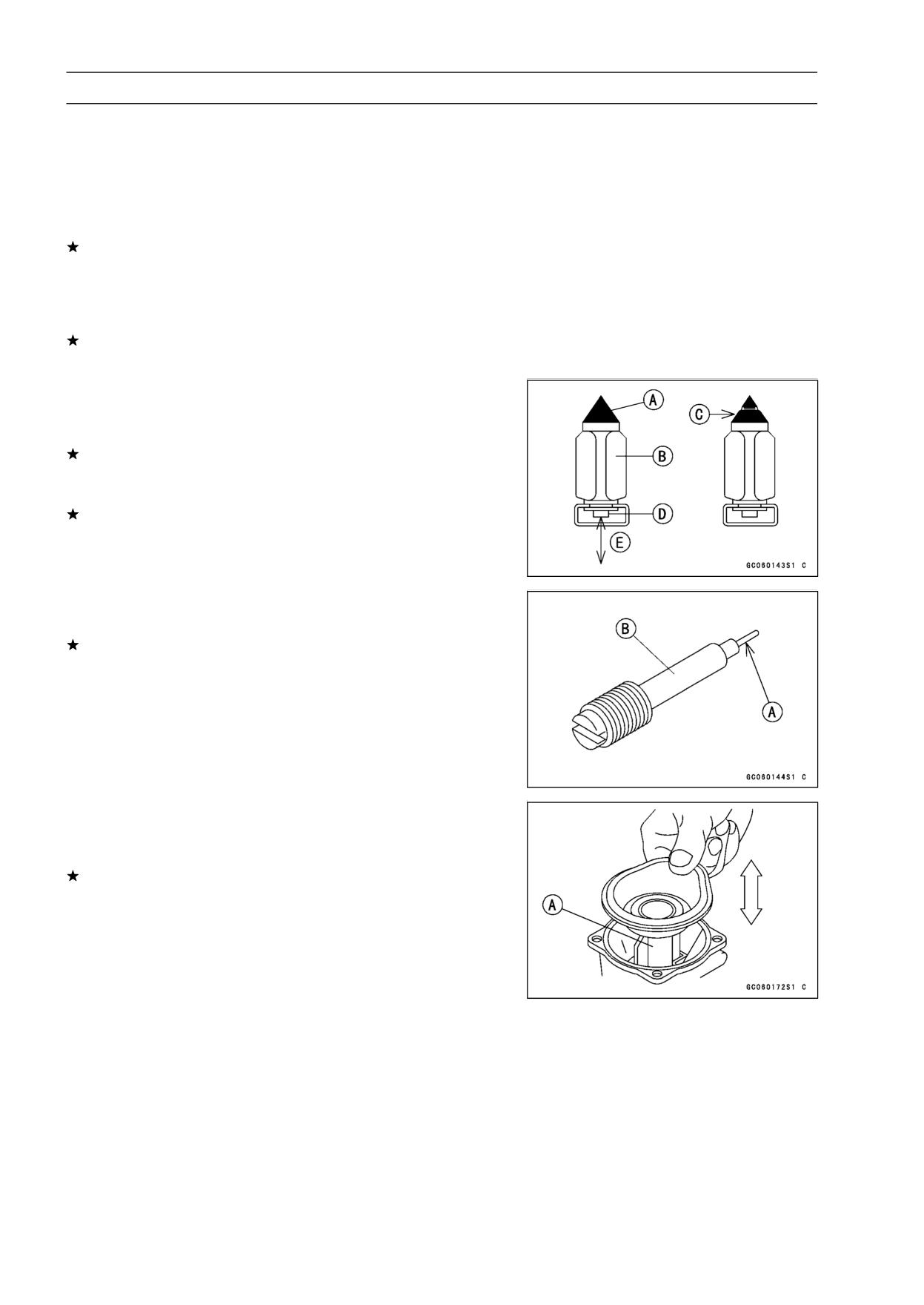
3-26 FUEL SYSTEM
Carburetors
• Disassemble the carburetors (see Carburetor Disassem-
bly).
• Clean the carburetors (see Carburetor Cleaning).
• Check that the O-rings on the float bowl and pilot screw
and the diaphragm on the vacuum piston are in good con-
dition.
If any of the O-rings or diaphragms are not in good con-
dition, replace them.
• Check the O-ring and diaphragm of coasting enricher sys-
tem.
If any of the O-ring or diaphragm are not in good condition,
replace them.
• Check the plastic tip [A] of the float valve needle [B]. It
should be smooth, without any grooves, scratches, or
tears.
If the plastic tip is damaged [C], replace the needle.
• Push the rod [D] in the other end of the float valve needle,
and then release it [E].
If the rod does not spring out, replace the needle.
• Check the tapered portion [A] of the pilot screw [B] for
wear or damage.
If the pilot screw is worn or damaged on the tapered por-
tion, it will prevent the engine from idling smoothly. Re-
place it.
• Check that the vacuum piston [A] moves smoothly in the
carburetor body. The surface of the piston must not be
excessively worn.
If the vacuum piston does not move smoothly, or if it is
very loose in carburetor body, replace the carburetor.
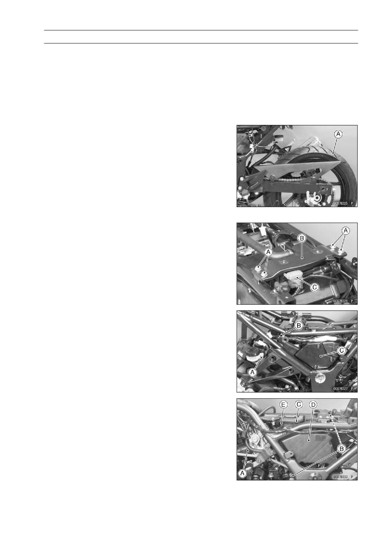
FUEL SYSTEM 3-27
Air Cleaner
Air Cleaner Element Removal
• Refer to Air Cleaner Cleaning in the Periodic Maintenance
chapter (see Air Cleaner Cleaning in the Periodic Mainte-
nance chapter).
Air Cleaner Element Installation
• Refer to Air Cleaner Cleaning in the Periodic Maintenance
chapter (see Air Cleaner Cleaning in the Periodic Mainte-
nance chapter).
Air Cleaner Housing Removal
• Remove:
Front Seat (see Front Seat Removal in the Frame chap-
ter)
Rear Seat (see Rear Seat Removal in the Frame chap-
ter)
Fuel Tank (see Fuel Tank Removal)
Rear Fender (see Rear Fender Removal in the Frame
chapter)
• Pull out the rear axle and place the rear wheel [A] on the
ground.
• Take out the bolts [A] and remove the fuel tank bracket
[B].
• Pull out the starter relay [C].
• Remove the rear brake reservoir bolt [A] and disconnect
the clamp [B], and free the rear brake reservoir and main
harness from the frame.
• Remove the air cleaner cap [C].
• Remove:
Carburetor Holder Clamps [A] (Loosen)
Air Cleaner Housing Mounting Bolts [B]
Air Suction Valve Hose [C]
• Remove the air cleaner housing [D], pulling out the duct
portion [E] from the grommet.
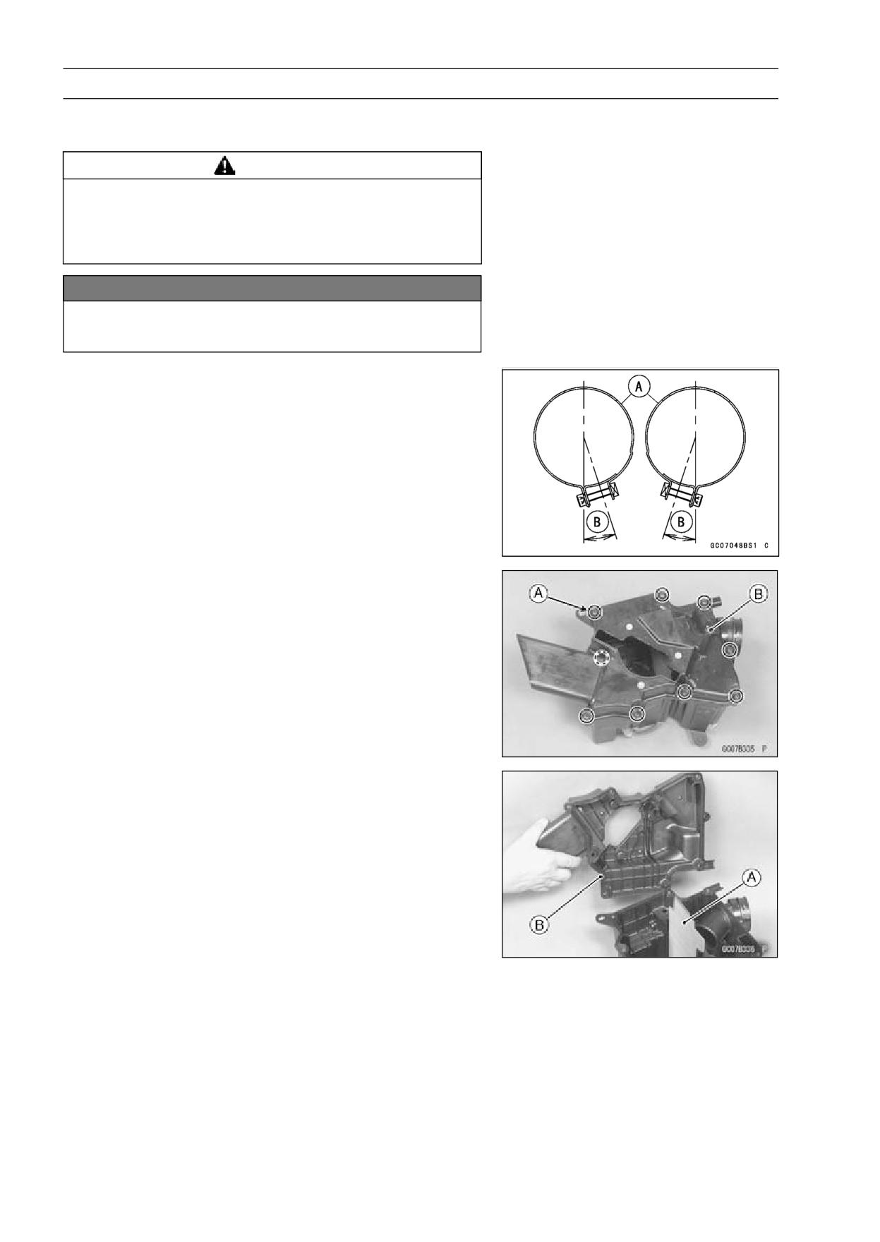
3-28 FUEL SYSTEM
Air Cleaner
• Cover the carburetors intakes with a clean, lint-free towel
to keep dirt or other foreign material from entering.
WARNING
If dirt or dust is allowed to pass through into the car-
buretors, the butterfly valves may become stuck,
possibly causing accident. Replace the air cleaner
element according to the maintenance chart.
NOTICE
If dirt gets through into the engine, excessive en-
gine wear and possibly engine damage will occur.
Air Cleaner Housing Installation
• Install the air cleaner housing clamps [A] as shown.
Approx. 18° [B]
Air Cleaner Housing Disassembly
• Remove:
Air Cleaner Housing (see Air Cleaner Housing Removal)
Air Cleaner Element (see Air Element Removal in the
Periodic Maintenance chapter)
Screw [A]
Right Cover [B]
Flame Arrester
Air Cleaner Housing Assembly
• Install the flame arrester [A].
• Be sure the O-ring [B] is in position.
//////////////////////////////////////////