Toyota Tundra. Manual - part 2059


  Index      Toyota     Toyota Tundra (2007-2010 year) - Service and Repair Manual


Search            copyright infringement  


Content   ..  2057  2058  2059  2060   ..


Toyota Tundra. Manual - part 2059


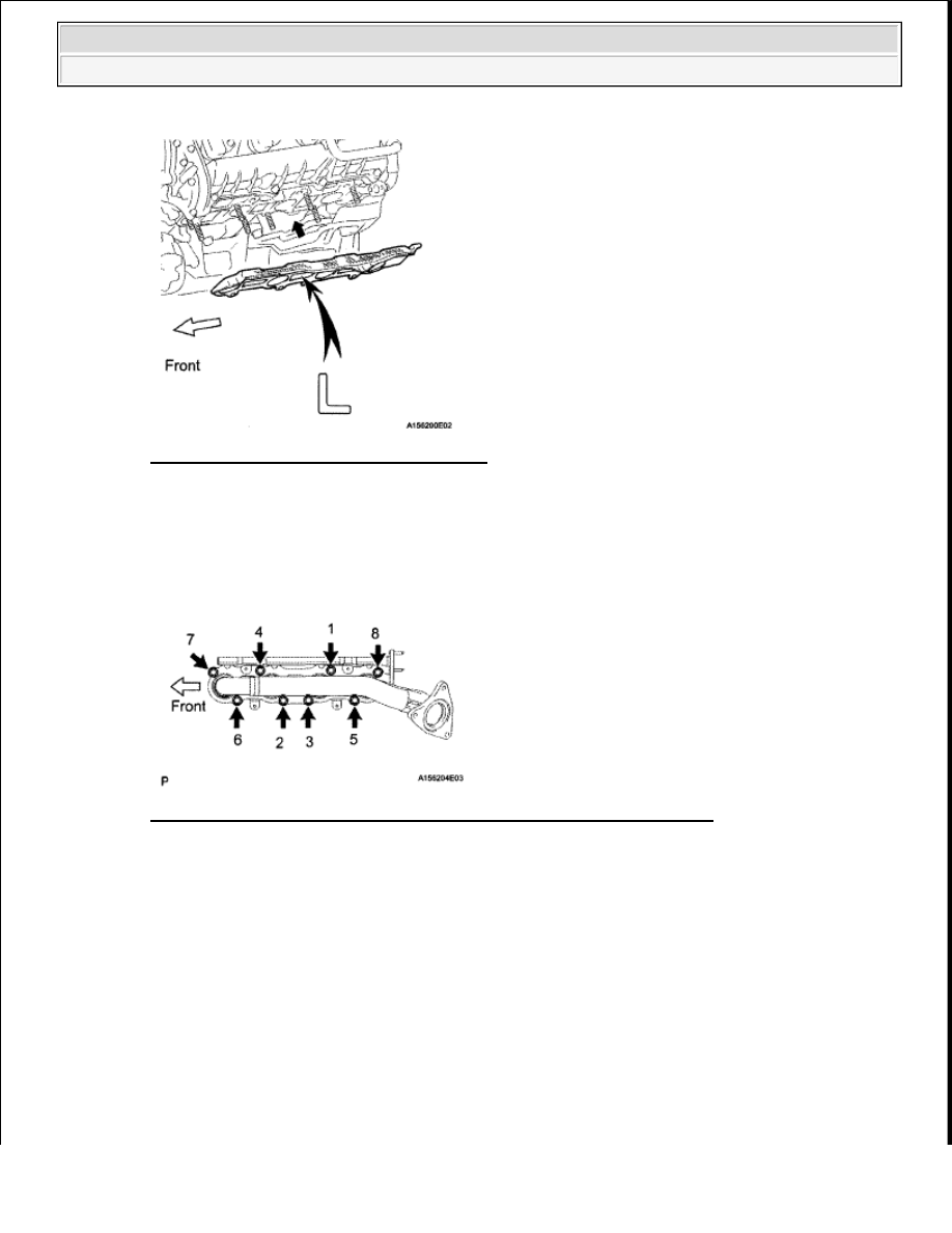
Fig. 17: Placing Gasket On Cylinder Head 
Courtesy of TOYOTA MOTOR SALES, U.S.A., INC. 

b

Temporarily install the exhaust manifold, and then uniformly tighten 8 new nuts in several steps, in 
the sequence shown in the illustration  

Torque: 44 N*m (449 kgf*cm, 32 ft.*lbf)  

Fig. 18: Tightening Exhaust Manifold Sub-Assembly Nuts In Sequence 
Courtesy of TOYOTA MOTOR SALES, U.S.A., INC. 

2

INSTALL NO. 2 EXHAUST MANIFOLD HEAT INSULATOR 

a

Temporarily install the heat insulator with the 4 bolts   

b

Uniformly tighten the 4 bolts in several steps, in the sequence shown in the illustration  

Torque: 7.5 N*m (76 kgf*cm, 66 in.*lbf)  


2009 Toyota Tundra 

2009 ENGINE Exhaust (2UZ-FE) - Tundra


Fig. 19: Identifying Heat Insulator With Bolts 
Courtesy of TOYOTA MOTOR SALES, U.S.A., INC. 

3

INSTALL NO. 2 STEERING INTERMEDIATE SHAFT SUB-ASSEMBLY (See 
INSTALLATION )  

4

INSTALL EXHAUST MANIFOLD SUB-ASSEMBLY RH 

a

Place a new gasket on the cylinder head with the "R" mark facing the manifold side  

Fig. 20: Placing Gasket On Cylinder Head 
Courtesy of TOYOTA MOTOR SALES, U.S.A., INC. 

b

Temporarily install the exhaust manifold, and then uniformly tighten 8 new nuts in several steps, in 
the sequence shown in the illustration  

Torque: 44 N*m (428 kgf*cm, 31 ft.*lbf)  

NOTE:

Be careful of the installation direction.


2009 Toyota Tundra 

2009 ENGINE Exhaust (2UZ-FE) - Tundra


Fig. 21: Tightening Exhaust Manifold Sub-Assembly Nuts In Sequence 
Courtesy of TOYOTA MOTOR SALES, U.S.A., INC. 

5

INSTALL NO. 1 EXHAUST MANIFOLD HEAT INSULATOR 

a

Temporarily install the heat insulator with the 4 bolts   

b

Uniformly tighten the 4 bolts in several steps, in the sequence shown in the illustration  

Torque: 7.5 N*m (76 kgf*cm, 66 in.*lbf)  

Fig. 22: Identifying Exhaust Manifold Heat Insulator With Bolts 
Courtesy of TOYOTA MOTOR SALES, U.S.A., INC. 

6

INSTALL FRONT NO. 2 EXHAUST PIPE ASSEMBLY (for Regular Cab Standard Deck) 

a

Install a new gasket and the front No  2 exhaust pipe to the exhaust manifold LH with 3 new nuts  

Torque: 54 N*m (554 kgf*cm, 40 ft.*lbf)  

b

Install a new gasket and the front No  2 exhaust pipe to the front No  3 exhaust pipe with the 2 bolts 
and 2 nuts  

Torque: 48 N*m (489 kgf*cm, 35 ft.*lbf)  

c

Connect the air fuel ratio sensor connector   

d

Connect the heated oxygen sensor connector   

7

INSTALL FRONT NO. 2 EXHAUST PIPE ASSEMBLY (except Regular Cab Standard Deck) 

a

Connect the front No  2 exhaust pipe to the exhaust support   

b

Install a new gasket and the front No  2 exhaust pipe to the exhaust manifold LH with 3 new nuts  


2009 Toyota Tundra 

2009 ENGINE Exhaust (2UZ-FE) - Tundra


Torque: 54 N*m (554 kgf*cm, 40 ft.*lbf)  

c

Install a new gasket and the front No  2 exhaust pipe to the center exhaust pipe with the 2 bolts  

Torque: 48 N*m (489 kgf*cm, 35 ft.*lbf)  

d

Connect the air fuel ratio sensor connector   

e

Connect the heated oxygen sensor connector   

8

INSTALL FRONT PROPELLER SHAFT ASSEMBLY (for 4WD) (See )  

9

INSTALL PROPELLER SHAFT HEAT INSULATOR (for 4WD) 

a

Install the heat insulator with the 2 bolts  

Torque: 16 N*m (160 kgf*cm, 12 ft.*lbf)  

Fig. 23: Locating Propeller Shaft Heat Insulator Bolts (4WD) 
Courtesy of TOYOTA MOTOR SALES, U.S.A., INC. 

10

INSTALL FRONT EXHAUST PIPE ASSEMBLY 

a

Install a new gasket and the front exhaust pipe to the exhaust manifold RH with 3 new nuts  

Torque: 54 N*m (554 kgf*cm, 40 ft.*lbf)  

b

Install a new gasket and the front exhaust pipe to the center exhaust pipe with the 2 bolts  

Torque: 48 N*m (489 kgf*cm, 35 ft.*lbf)  

c

Connect the air fuel ratio sensor connector   

d

Connect the heated oxygen sensor connector and 2 clamps   

11

INSTALL AIR SWITCHING VALVE ASSEMBLY (See INSTALLATION )  

12

INSTALL NO. 2 AIR TUBE (for Bank 2) (See INSTALLATION )  

13

CONNECT NO. 2 AIR INJECTION SYSTEM HOSE (See INSTALLATION )  

14

INSTALL WATER BY-PASS PIPE ASSEMBLY 

a

Connect the 2 water hoses to the transmission oil cooler  


2009 Toyota Tundra 

2009 ENGINE Exhaust (2UZ-FE) - Tundra


Content   ..  2057  2058  2059  2060   ..