Toyota Tundra. Manual - part 1831


  Index      Toyota     Toyota Tundra (2007-2010 year) - Service and Repair Manual


Search            copyright infringement  


Content   ..  1829  1830  1831  1832   ..


Toyota Tundra. Manual - part 1831


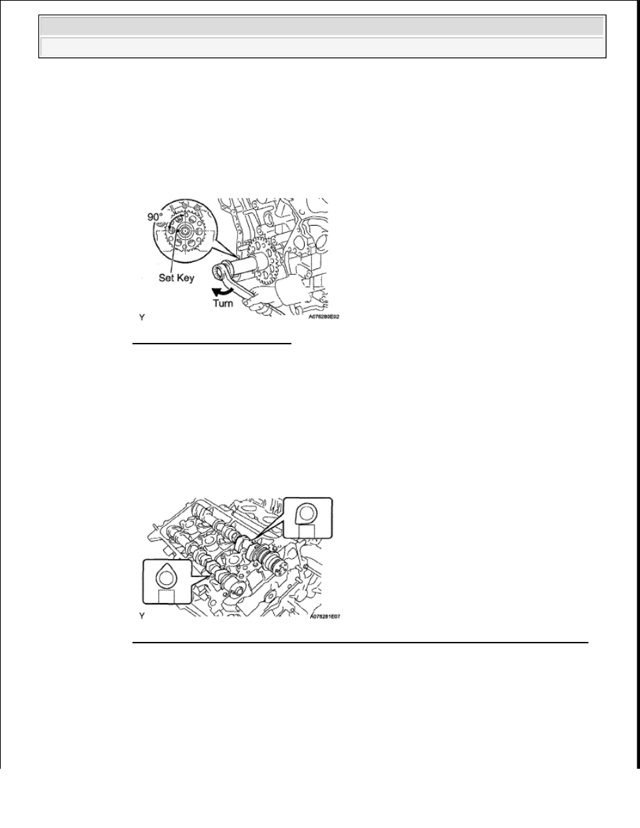
the left horizontal position  

Fig. 378: Turning Crankshaft 
Courtesy of TOYOTA MOTOR SALES, U.S.A., INC. 

b

for Bank 1: 

Apply new engine oil to the thrust portion and journal of the camshafts  

c

Install the camshaft  

1

Place the 2 camshafts onto the cylinder head with the cam lobes of the No  1 cylinder facing 
each direction as shown below  

Fig. 379: Placing Camshafts Onto Cylinder Head With Cam Lobes Of No. 1 Cylinder 
Courtesy of TOYOTA MOTOR SALES, U.S.A., INC. 

2

Install the 8 bearing caps in their proper locations   

3

Apply a light coat of engine oil to the threads and under the heads of the bearing cap bolts  

NOTE:

Having the crankshaft at the wrong angle can cause the piston 
head and valve head to come into contact with each other when 
the camshaft is installed, causing damage. Always set the 
crankshaft at the correct angle.


2009 Toyota Tundra 

2009 ENGINE Engine Mechanical (1GR-FE) - Tundra


Fig. 380: Identifying Bearing Caps Location 
Courtesy of TOYOTA MOTOR SALES, U.S.A., INC. 

4

Uniformly install the 16 bolts in several steps in the order shown below  

Torque: for 10 mm head  

9.0 N*m (92 kgf*cm, 80 in.*lbf)  

for 12 mm head  

24 N*m (245 kgf*cm, 18 ft.*lbf)  

Fig. 381: Identifying Bolt Torque Sequence 
Courtesy of TOYOTA MOTOR SALES, U.S.A., INC. 

5

Using a wrench, turn the camshafts clockwise until the camshaft knock pin is at a position 
90° to the cylinder head  


2009 Toyota Tundra 

2009 ENGINE Engine Mechanical (1GR-FE) - Tundra


Fig. 382: Turning Camshafts Clockwise Using Wrench 
Courtesy of TOYOTA MOTOR SALES, U.S.A., INC. 

d

for Bank 2: 

Install the camshafts  

1

Place the 2 camshafts onto the cylinder head with the cam lobes of the No  2 cylinder facing 
as shown below  

Fig. 383: Placing Camshafts Onto Cylinder Head With Cam Lobes Of No. 2 Cylinder 
Courtesy of TOYOTA MOTOR SALES, U.S.A., INC. 

2

Install the 8 bearing caps in their proper locations   

3

Apply a light coat of engine oil to the threads and under the heads of the bearing cap bolts  

Fig. 384: Identifying Bearing Caps Installing Locations 


2009 Toyota Tundra 

2009 ENGINE Engine Mechanical (1GR-FE) - Tundra


Courtesy of TOYOTA MOTOR SALES, U.S.A., INC. 

4

Uniformly install the 16 bolts in several steps in the order shown below  

Torque: for 10 mm head  

9.0 N*m (92 kgf*cm, 80 in.*lbf)  

for 12 mm head  

24 N*m (245 kgf*cm, 18 ft.*lbf)  

Fig. 385: Identifying Bolt Torque Sequence 
Courtesy of TOYOTA MOTOR SALES, U.S.A., INC. 

12

INSTALL NO. 2 CHAIN TENSIONER ASSEMBLY (for Bank 1) 

a

While pushing in the tensioner, insert a pin of 1 0 mm (0 0394 in ) into the hole to fix it  

Fig. 386: Pushing No. 2 Chain Tensioner 
Courtesy of TOYOTA MOTOR SALES, U.S.A., INC. 

b

Install the No  2 chain tensioner with the bolt  

Torque: 21 N*m (214 kgf*cm, 15 ft.*lbf)  


2009 Toyota Tundra 

2009 ENGINE Engine Mechanical (1GR-FE) - Tundra


Content   ..  1829  1830  1831  1832   ..