Suzuki Grand Vitara JB416 / JB420 / JB419. Manual - part 332


  Index      Suzuki     Suzuki Grand Vitara JB416 / JB420 / JB419 - service repair manual 2007 year


Search            


Content   ..  330  331  332  333   ..


Suzuki Grand Vitara JB416 / JB420 / JB419. Manual - part 332


5A-119 Automatic Transmission/Transaxle: 

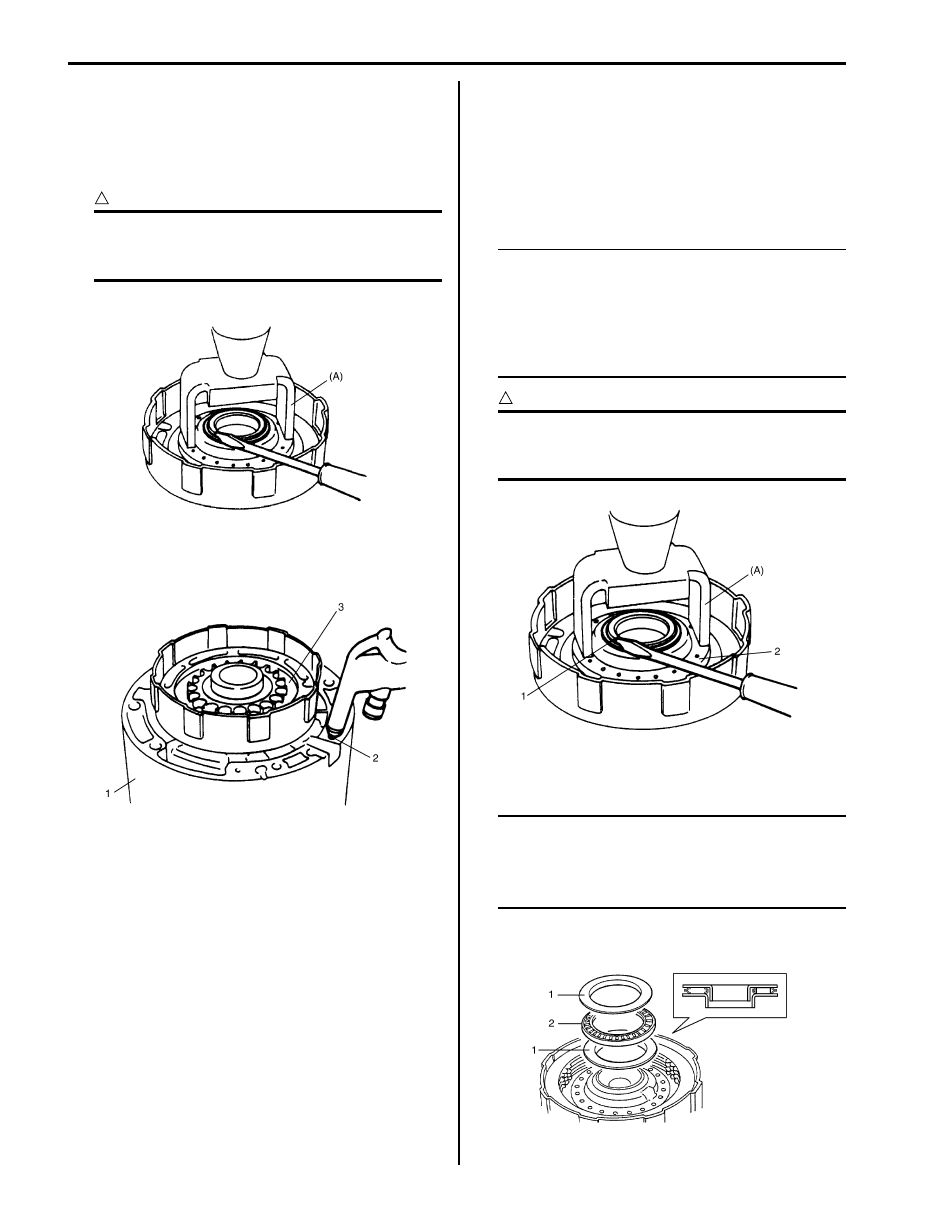
4) Using special tool and hydraulic press, compress 

forward clutch piston return spring and remove 
retaining return spring.

Special tool
(A):  09926–98310 

CAUTION

!


Be careful when applying pressure, for 
overpressure will cause plate section of 
piston return spring to deform.


5) Remove forward clutch piston return spring.

6) Install forward clutch to O/D case (1). Blow low 

pressure air into fluid hole (2) at the right of cut in O/
D case to remove forward clutch piston (3).

Assembly

1) Apply A/T fluid to forward input shaft O-rings, install 

forward clutch piston and piston return spring (2) to 
forward input shaft and then install return spring ring 
with special tool and hydraulic press.

Special tool
(A):  09926–98310 

NOTE

• When installing return spring (2), be 

careful so that return spring will not fall or 
tilt.

• Do not align opening in retaining ring (1) 

with lug of forward clutch piston return 
spring at its retainer section.


CAUTION

!


Be careful when applying pressure, for 
overpressure will cause plate section of 
piston return spring to deform.


2) Install clutch discs and plates and then install 

retaining clutch ring.

NOTE

• Refer to “Forward Clutch Components” 

when installing each component.

• Do not match opening in retaining clutch 

ring and dent in forward clutch input shaft.


3) Install bearing races (1) and thrust bearing (2).

IYSQ01510148-01

I5JB0A510110-01

IYSQ01510150-01

I5JB0A510111-01

Automatic Transmission/Transaxle:  5A-120

4) Install forward clutch hub (3), direct clutch hub (2) 

and retaining ring (1) in that order.

5) Install forward clutch (2) to O/D case (1). Apply 

compressed air (400 – 800 kPa, 4 – 8 kg/cm

2

, 57 – 

113 psi) to oil hole at the right of cut in O/D case and 
measure movement of forward clutch piston.
If measured value is not within standard range, 
select another plate with suitable thickness from the 
list below and replace it.

Standard forward clutch piston movement
1.40 – 1.70 mm (0.055 – 0.067 in.)

Forward Clutch Inspection

S6JB0A5106041

Forward Clutch Piston
• Shake piston to check that ball is not stuck.
• Blow low pressure air to check ball section for 

leakage.

Forward Clutch Piston Return Spring
• Measure free length.

Standard free length of forward clutch piston 
return spring
24.81 mm (0.977 in.)

Clutch Plate and Disc
• Check that sliding surface of discs and plate are not 

worn or burnt. If necessary, replace them.

NOTE

• If disc lining is exfoliated, discolored or 

worn hardly, replace all discs.

• If only a part of printed numbers is 

corroded, replace all discs.

• Before assembling new discs, soak them 

in A/T fluid for at least 15 minutes.


4. Input shaft

Thickness

1.75 – 1.85 mm (0.069 – 0.073 in.)
1.95 – 2.05 mm (0.077 – 0.081 in.)

IYSQ01510151-01

2

1

I5JB0A510150-01

IYSQ01510152-01

I5JB0A510171-01

I4JA01512210-01

5A-121 Automatic Transmission/Transaxle: 

Direct Clutch Components

S6JB0A5106042

Direct Clutch Disassembly and Assembly

S6JB0A5106043

Disassembly

1) Remove direct clutch assembly from center support 

and then remove retaining ring.

2) Remove clutch backing plate (1) and then remove 

clutch disc (3) and clutch plate (2).

10

11

3

8

6

5

4

2

1

3

9

7

FLD

FLD

FLD

8

FLD

I5JB0A510112-01

1. Bearing race

5. Clutch disc

9. Direct clutch piston

: Apply A/T fluid.

2. Bearing

6. Clutch plate

10. Direct clutch inner piston

3. Retaining ring

7. Return spring

11. Direct clutch cylinder

4. Clutch backing plate

8. O-ring

: Do not reuse.

IYSQ01510156-01

2

1

3

I5JB0A510114-01

Automatic Transmission/Transaxle:  5A-122

3) Using special tool and hydraulic press (1), compress 

direct clutch piston return spring (3) and remove 
retaining return spring ring (2).

Special tool
(A):  09926–98310 

CAUTION

!


Be careful when applying pressure, for 
overpressure will cause plate section of 
piston return spring to deform.


4) Remove direct clutch piston return spring.
5) Install direct clutch cylinder to center support.

Remove direct clutch piston by blowing air into the 
second hole from the left as shown in the figure. 
Also, remove direct clutch inner piston by blowing air 
into hole at the extreme right. And then remove O-
rings from pistons.

Assembly
Assemble each component by reversing disassembly 
procedure and noting the following points.
• Always use new O-ring and apply A/T fluid before 

installation.

• Do not align opening in retaining ring (2) with lug of 

direct clutch piston return spring at retainer.

Special tool
(A):  09926–98310 

• Use care so that direct clutch piston return spring will 

not fall or tilt.

CAUTION

!


Be careful when applying pressure, for 
overpressure will cause plate section of 
piston return spring to deform.


• Do not match opening (1) in retaining back plate ring 

with cutout (2) in direct clutch cylinder.

• Install clutch backing plate with its grooved side (1) 

facing the front.

IYSQ01510158-01

IYSQ01510159-01

1. Hydraulic press

[A]: Front

IYSQ01510160-01

IYSQ01510161-01

I5JB0A510115-01


Content   ..  330  331  332  333   ..