Suzuki Grand Vitara JB416 / JB420 / JB419. Manual - part 333


  Index      Suzuki     Suzuki Grand Vitara JB416 / JB420 / JB419 - service repair manual 2007 year


Search            


Content   ..  331  332  333  334   ..


Suzuki Grand Vitara JB416 / JB420 / JB419. Manual - part 333


5A-123 Automatic Transmission/Transaxle: 

• Install direct clutch assembly (1) to center support (2) 

and with compressed air (400 – 800 kPa, 4 – 8 kg/
cm

2

, 57 – 113 psi) applied to oil hole (3), measure 

stroke of direct clutch piston as shown in the figure.
If it is not within standard range, select another plate 
with suitable thickness from the list below and replace 
it.

Direct clutch piston standard stroke
0.90 – 1.30 mm (0.035 – 0.051 in.)

Direct Clutch Inspection

S6JB0A5106044

• Measure inside diameter of direct clutch cylinder 

bushing. If inside diameter exceeds limit, replace 
direct clutch cylinder.

Direct clutch cylinder bushing inside diameter 
standard
23.062 – 23.088 mm (0.9080 – 0.9090 in.)

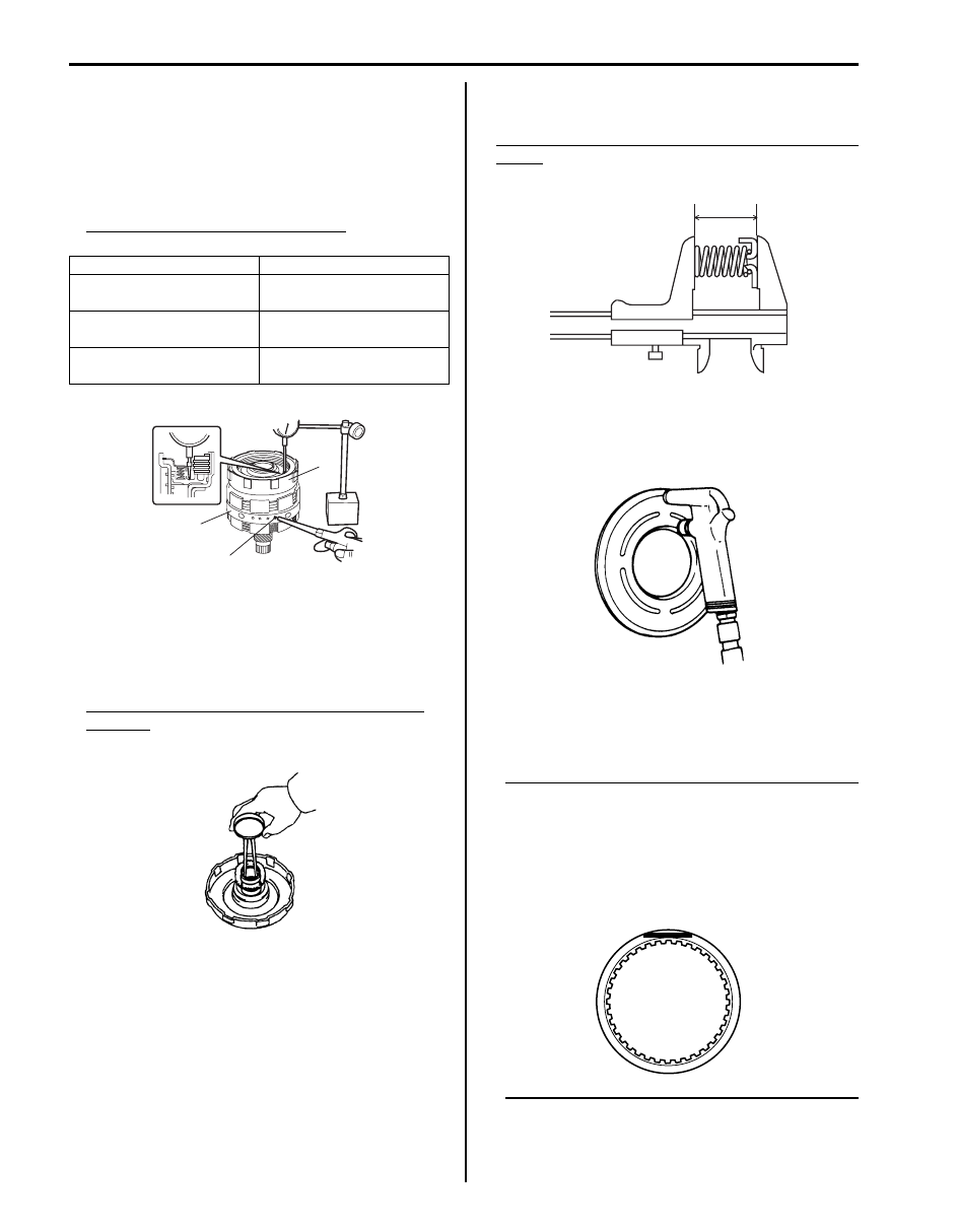
Direct Clutch Piston Return Spring
• Measure free length.

Standard free length of direct clutch piston return 
spring
24.25 mm (0.955 in.)

Direct Clutch Piston
• Shake piston to check that ball is not stuck.
• Apply air pressure and check that there is no leakage.

Clutch Disc and Plate
Check that sliding surface of discs and plate are not 
worn or burnt. if necessary, replace them.

NOTE

• If disc lining is exfoliated, discolored or 

worn hardly, replace all discs.

• If only a part of printed numbers is 

corroded, replace all discs.

• Before assembling new discs, soak them 

in A/T fluid for at least 15 minutes.


Identification No.

Thickness

No identification

3.925 – 4.050 mm

(0.155 – 0.159 in.)

“B”

3.675 – 3.800 mm

(0.145 – 0.150 in.)

“A”

3.475 – 3.600 mm

(0.137 – 0.142 in.)

2

3

1

I5JB0A510113-01

I5JB0A510156-01

I5JB0A510171-01

IYSQ01510163-01

I4JA01512210-01

Automatic Transmission/Transaxle:  5A-124

Center Support Components

S6JB0A5106045

1

3

4

5

8

11

4

5

9

15

14

9

9

2

FLD

2

FLD

10

FLD

10

FLD

6

FLD

7

FLD

13

FLD

12

FLD

I5JB0A510116-02

1. Center support

6. Second coast brake plate

11. Second brake piston

: Do not reuse.

2. O-ring

7. Second coast brake disc

12. Second brake plate

: Apply A/T fluid.

3. Second coast brake piston

8. Clutch backing plate

13. Second brake disc

4. Piston return spring

9. Retaining ring

14. Planetary sun gear

5. Snap ring

10. Seal ring

15. Second brake hub assembly

5A-125 Automatic Transmission/Transaxle: 

Center Support Disassembly and Assembly

S6JB0A5106046

Disassembly

1) Remove retaining ring.

Special tool
(A):  09920–76010 

2) Pull out center support assembly (2) from planetary 

sun gear (1).

3) Apply compressed air (400 – 800 kPa, 4 – 8 kg/cm

2

57 – 113 psi) to oil hole (1) at the extreme left and 
measure movement of second coast brake (Second 
coast brake) piston.
If measured value is not within standard range, 
replace second coast brake plate or second coast 
brake disc.

Standard second coast brake piston movement
0.75 – 1.35 mm (0.030 – 0.053 in.)

4) Remove retaining ring.

5) After removing clutch backing plate (1), remove 

second coast brake plate (3) and second coast 
brake disc (2).

6) Using special tool and hydraulic press, compress 

piston return spring and remove snap ring.

CAUTION

!


Be careful when applying pressure, for 
overpressure will cause plate section of 
piston return spring to deform.


Special tool
(A):  09926–98310 

7) Remove brake piston return spring (1).

IYSQ01510165-01

1

2

I5JB0A510117-01

1

I5JB0A510118-01

IYSQ01510168-01

2

3

1

I5JB0A510119-02

IYSQ01510170-01

IYSQ01510171-01

Automatic Transmission/Transaxle:  5A-126

8) Apply compressed air (400 – 800 kPa, 4 – 8 kg/cm

2

57 – 113 psi) to oil hole at the extreme left and 
remove second coast brake piston as shown in the 
figure. Then remove piston inner O-ring and piston 
outer O-ring from second coast brake piston.

9) Remove 3 seal rear rings (1).

NOTE
Use care not to open ring more than 
necessary.


10) Apply compressed air (400 – 800 kPa, 4 – 8 kg/cm

2

57 – 113 psi) to second hole (1) from the left and 
measure stroke of second brake (Second brake) 
piston as shown in the figure.
If measured value is not within standard range, 
replace second brake plate or second brake disc.

Standard second brake piston stroke
0.97 – 1.70 mm (0.038 – 0.067 in.)

11) After removing retaining back plate ring, remove 

clutch backing plate, second brake plates and 
second brake discs.

12) Using special tool and hydraulic press, compress 

brake piston return spring and remove snap second 
coast brake ring.

CAUTION

!


Be careful when applying pressure, for 
overpressure will cause plate section of 
piston return spring to deform.


Special tool
(A):  09926–98310 

13) Remove brake piston return spring.

IYSQ01510172-01

IYSQ01510173-01

1

I5JB0A510120-01

IYSQ01510175-01

IYSQ01510176-01

IYSQ01510177-01


Content   ..  331  332  333  334   ..