Suzuki Grand Vitara JB416 / JB420. Manual - part 195
3D-6 Propeller Shaft:
Specifications
Tightening Torque Specifications
S5JB0A3407001
NOTE
The specified tightening torque is also described in the following.
“Propeller Shaft Construction”
Reference:
For the tightening torque of fastener not specified in this section, refer to “Fastener Information in Section 0A”.
Special Tools and Equipment
Recommended Service Material
S5JB0A3408001
NOTE
Required service material is also described in the following.
“Propeller Shaft Construction”
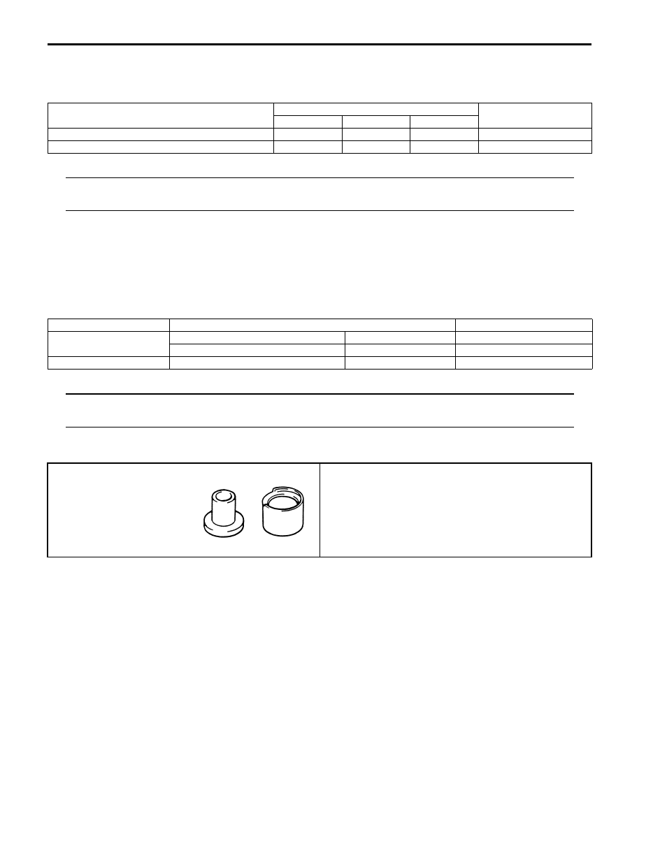
Special Tool
S5JB0A3408002
Fastening part
Tightening torque
Note
N
⋅m
kgf-m
lb-ft
Front propeller shaft flange bolt
30
3.0
22.0
Rear propeller shaft flange nut
85
8.5
61.5
Material
SUZUKI recommended product or Specification
Note
Grease
SUZUKI Super Grease A
P/No.: 99000–25010
SUZUKI Super Grease C
P/No.: 99000–25030
Thread lock cement
Thread Lock Cement Super 1322
P/No.: 99000–32110
09926–48010
Universal joint assembling
tool
)