Opel Frontera UE. Manual - part 101


  Index      Opel     Opel Frontera UE - service repair manual 1999-2001 year


Search            


Content   ..  99  100  101  102   ..


Opel Frontera UE. Manual - part 101


4C–38

DRIVE SHAFT SYSTEM

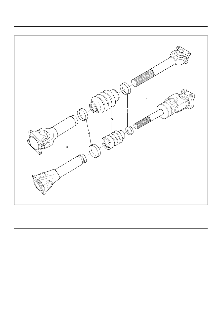
Slip Joint Reassembly

401RW075

Legend

EndOFCallout

1. Apply grease evenly to both the female and male 

splines.

2. Apply a small amount of grease by finger to the 

outer lips of the boot.

3. Slide the boot (smaller diameter side) onto the 

spline yoke shaft being careful not to damage the 
spline coating or boot.

4. Insert the spline yoke shaft into the tube assembly 

being careful to maintain proper phasing.  The 
spider holes should be in line and as per originally 
marked prior to disassembly.

5. Position boot onto tube and yoke shaft in final 

position over boot grooves.

6. Attach boot clamps and secure using pliers.

7. Be sure clamp is properly seated and secure.

CAUTION:  Use new clamp which is the same parts 
as original. Do not use other clamp to avoid bad 
balancing of shaft or the grease leakage.

(1) Spline Yoke shaft
(2) Clamp
(3) Boot

(4) Clamp
(5) Tube Assembly

DRIVE SHAFT SYSTEM

4C–39

Main Data and Specifications

General Specifications

Torque Specifications

401RX027

Length (between two spiders 
center)

M/T

A/T

6VD1

376 mm (14.80 in)

542 mm (21.34 in)

X22SE

294 mm (11.57 in)

4C–40

DRIVE SHAFT SYSTEM

Rear Propeller Shaft

Rear Propeller Shaft and Associated Parts

401RX028

Legend

EndOFCallout

Removal

1. Raise the vehicle on a hoist.

NOTE:  Apply alignment marks on the flange at the rear 
propeller shaft both front and rear side.

2. Remove transfer side bolt, nut and washer.

3. Remove rear axle side bolt, nut and washer.

4. Remove rear propeller shaft.

Installation

NOTE:  Never install the shaft assembly backwards.
Never insert bar between yoke lugs when tightening or 
removing bolts.
Completely remove the dust or foreign matter from the 
connecting surface of flange coupling on each end of 
the propeller shaft.

1. Align the mark which is applied at removal.

2. Install rear propeller shaft and tighten the bolts to 

the specified torque.

Torque:63 N·m(6.4kg·m/46lbft)

(1) Bolt, Nut and Washer (Transfer Side)
(2) Rear Propeller Shaft

(3) Bolt, Nut and Washer (Rear Axle Side)

DRIVE SHAFT SYSTEM

4C–41

Slip Joint Disassembly

401RX004

Legend

EndOFCallout

1. Lay the shaft horizontally on a bench and secure.

2. Indicate the original assembled position by marking 

the phasing of the shaft prior to disassembly.

3. Using the flat blade of a screwdriver, pry the loose 

end of the boot clamp upwards and away from the 
propeller shaft boot. Be careful not to damage the 
boot.

4. When boot clamps becomes loose, remove by 

hand.

5. Repeat for the other boot clamp.

6. Remove the slip yoke assembly from the driveshaft, 

by securing the boot with one hand and pulling on 
the slip yoke.

7. Remove the boot from the shaft assembly.

(1) Spline Yoke and Universal Joint Assembly
(2) Clamp
(3) Boot

(4) Clamp
(5) Tube and Universal Joint Assembly


Content   ..  99  100  101  102   ..