Opel Frontera UE. Manual - part 100


  Index      Opel     Opel Frontera UE - service repair manual 1999-2001 year


Search            


Content   ..  98  99  100  101   ..


Opel Frontera UE. Manual - part 100


4C–34

DRIVE SHAFT SYSTEM

Spider pin for wear

Spider pin should be smooth and free from fretting or 
galling.  Visible signs of needle presence is normal, but 
wear should not be felt.

401RW038

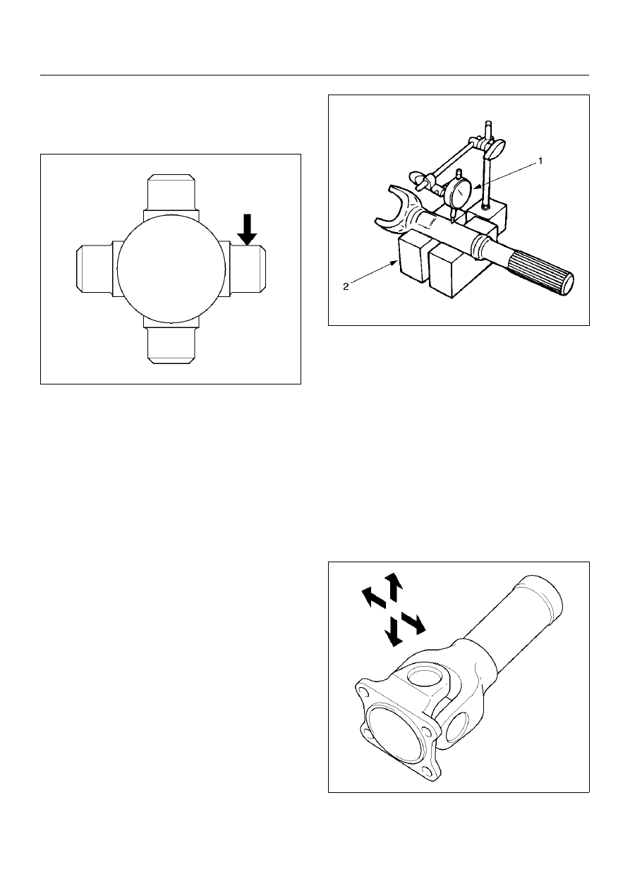
Propeller shaft runout

Support the propeller shaft on V-blocks (2) and check 
for runout by holding the probe of a dial indicator (1) in 
contact with the shaft.

Static runout limit:

0.13mm (0.005in)

TIR on the neck of the slip tube shaft (with a 
boot).

0.25mm (0.010in)

TIR on the ends of the tubing 3 inch from the 
welds.

0.38mm (0.015in)

TIR at the linear center of the tube.

0.38mm (0.015in)

TIR for the full length of tube with 30" or less of 
tubing.

(TIR : Total Indicator Reading)

401RS027

Spline

The nylon-coated spline should be free from nicks and 
dings and the underlying steel spline should not be 
visible.
After cleaning the nylon coating spline, the coating 
should exhibit only a slight indication of wear.
Grease volume is approximately 10 grams of grease in 
total.  Grease should be evenly applied to both the 
female and  the male slip splines using a small brush.  
After assembly of the slip joint, the sliding joint should 
be fully worked from the full collapsed to the full 
extended position.

Play in the universal joint

Limit:Less than0.15mm (0.006 in)

401RW023

DRIVE SHAFT SYSTEM

4C–35

Preload of the universal joint

Preload should be 0 to 24.9 kg(0 to11.3 lb).  Joints 
should rotate smoothly and freely and should exhibit no 
rough or ratchety movement.

401RW085

Boot

Check the boot for crack or damage. If necessary, 
replace the boot.
If abnormal condition are found on the boot, inspect the 
grease for mixing of foreign material.
If the grease is good condition, and slip joint works well, 
replace the boot, replenish grease, and reassemble the 
slip joint.
If the foreign material is found in the grease, check the 
spline for wear and damage.

Universal Joint Reassembly (Single 
Cardan Type)

1. Install spider to flange yoke. Be sure to install the 

spider by aligning the setting marks made during 
disassembly.

2. Pack the four grease cavities of the spider with a 

high quality, extreme pressure N.L.G.I. Grade 2 
grease.  Do not add additional grease to the bearing 
cup assembly.

3. Move one end of the spider to cause a trunnion to 

project through the spider hole beyond the outer 
machined face of the yoke lug.  Place a bearing over 
the trunnion diameter and align it to the spider hole.  
Using an arbor press, hold the trunnion in alignment 
with the spider hole and place a solid plug on the 
upper bearing.  Press the bearing into the spider 
hole enough to install a snap ring.

401RW020

4. Install a snap ring.

Be sure the snap rings are properly seated in the 
grooves.

5. Repeat steps 3 and 4 to install the opposite bearing.  

If the joint is stiff, strike the yoke ears with a soft 
hammer to seat needle bearings.

6. Align setting marks (1) and join the yokes.

401RW018

7. Install snap ring.

4C–36

DRIVE SHAFT SYSTEM

Universal Joint Reassembly (Double 
Cardan Type)

1. Pack the four grease cavities of the cross with a high 

quality, extreme pressure N.L.G.I. Grade 2 grease. 
Do not add additional grease to bearing cup 
assembly.

2. Fit a cross into the tube yoke.

401RW069

3. Move an end of the cross to cause a trunnion to 

project through the cross hole beyond the outer 
machined face of the yoke lug. Place a bearing cup 
assembly over the trunnion diameter and align it to 
the cross hole. Using an arbor press, hold the 
trunnion in alignment with the cross hole and place 
a solid plug on the upper bearing cup assembly.
Press the bearing cup assembly into the cross hole 
enough to install a snap ring.

401RW070

4. Install a snap ring.

5. Repeat steps 3 and 4 to install the opposite bearing 

cup assembly. If the joint is stiff, strike the yoke ears 
with a soft hammer to seat the needle bearing.

NOTE:  Be sure the snap rings are properly seated in 
the grooves.

401RW071

6. Fit the center yoke (“H” Yoke) on the remaining two 

trunnions and press bearing assemblies in place, 
both sides as in steps 3 and 4 above. Install snap 
rings.

401RW086

DRIVE SHAFT SYSTEM

4C–37

7. Install the journal onto the flange as per steps 3 and 

4 above.

8. Install the centering kit assembly inside the center 

yoke making sure the spring in the tube yoke is in 
place.

401RW072

9. Fit the open trunnions of the flange assembly in to 

the center yoke holes and the bearing assemblies 
into the centering kit assembly.

10. Install bearings as per steps 3 and 4.

11. Check for proper assembly. Flex the double cardan 

joint beyond center. The joint should snap over 
cener in both directions when all needle rollers and 
components are correctly assembled.


Content   ..  98  99  100  101   ..