Nissan Versa Sedan. Manual - part 784


  Index      Nissan     Nissan Versa Sedan (2014 year) - Service and Repair Manual


Search            


Content   ..  782  783  784  785   ..


Nissan Versa Sedan. Manual - part 784


TM-42

< UNIT DISASSEMBLY AND ASSEMBLY >

[5MT: RS5F91R]

TRANSAXLE ASSEMBLY

CAUTION:

• Do not reuse differential side oil seal.

• Do not tilt differential side oil seal.

• Do not damage clutch housing and transaxle case.

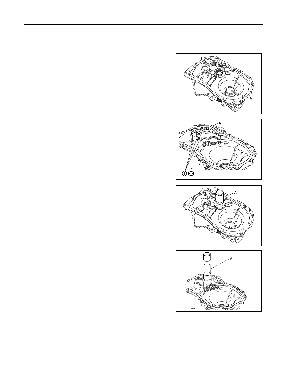
13. Install differential side bearing outer races until they reach clutch

housing and transaxle case, using Tool (A).

CAUTION:

Replace differential side bearing outer race and differential

side bearing as a set.

14. Install bushings (1) until they reach clutch housing, using suit-

able tool (A).

CAUTION:

Do not reuse bushings.

15. Install oil channel to clutch housing.

CAUTION:

Do not reuse oil channel.

16. Install mainshaft front bearing so that it becomes even with

clutch housing surface, using Tool (A).

17. Install input shaft front bearing so that it becomes even with

clutch housing surface, using Tool (A).

18. Install pinion gear, pinion shaft, and plug to clutch housing.

Tool number

: KV32300QAE ( — )

PCIB1549E

JPDIC0637ZZ

Tool number : ST33400001 ( — )

PCIB1544E

Tool number

: KV40100900 ( — )

PCIB1545E

TRANSAXLE ASSEMBLY

TM-43

< UNIT DISASSEMBLY AND ASSEMBLY >

[5MT: RS5F91R]

C

E

F

G

H

I

J

K

L

M

A

B

TM

N

O

P

19. Install final drive (1) to clutch housing.
20. Install dowel pins (2) and magnet to clutch housing.

CAUTION:

Do not reuse dowel pins.

21. Install reverse gear to clutch housing, and then install retaining

pin to clutch housing, using suitable tool.

CAUTION:

Do not reuse retaining pin.

22. Install 1st-2nd shift fork to 1st-2nd fork rod, and then install

retaining pin to 1st-2nd shift fork.

CAUTION:

• Do not reuse retaining pin.

• Replace 1st-2nd fork rod and 1st-2nd shift fork as a set.

23. Set 1st-2nd fork rod assembly (1) onto mainshaft assembly (2),

and then install them to clutch housing.

24. Install lock pins (

) to clutch housing.

25. Install 3rd-4th shift fork to 3rd-4th fork rod, and then install

retaining pin to 3rd-4th shift fork.

CAUTION:

• Do not reuse retaining pin.

• Replace 3rd-4th fork rod and 3rd-4th shift fork as a set.

26. Install 3rd-4th fork rod assembly (1), 3rd-4th coupling sleeve (2),

and input shaft assembly (3) to clutch housing.

a. Pull 1st-2nd fork rod (4) up, and then maintain the neutral posi-

tion.

b. Set 3rd-4th fork rod assembly onto 3rd-4th coupling sleeve, and

then install them together with input shaft assembly to clutch

housing.

CAUTION:

• Set lock pin (3rd-4th fork rod side) onto 1st-2nd fork rod

groove and then install 3rd-4th fork rod assembly.

PCIB1533E

MCIB0033E

PCIB1532E

JPDIC0534ZZ

PCIB1628E

TM-44

< UNIT DISASSEMBLY AND ASSEMBLY >

[5MT: RS5F91R]

TRANSAXLE ASSEMBLY

• Be careful with the orientation of 3rd-4th coupling sleeve.

• Install 3rd input gear of input shaft assembly so that it is

set under reverse main gear of 3rd-4th coupling sleeve.

• Replace 3rd-4th coupling sleeve and 3rd-4th synchronizer

hub as a set.

c.

Install springs and insert keys to 3rd-4th synchronizer hub.

d. Apply gear oil to 4th baulk ring.
e. Install 4th baulk ring.

27. Install 5th-reverse fork rod (1) to clutch housing.

CAUTION:

Replace 5th-reverse fork rod and 5th-reverse shift fork as a

set.

a. Pull gear of reverse gear (2) up.
b. Temporarily install 5th-reverse fork rod to clutch housing.

c.

Press gear of reverse gear (1) down and then install 5th-reverse

fork rod (2) to clutch housing.

CAUTION:

Set levers of 5th-reverse fork rod so as to align with reverse
gear groove ( ).

28. Install 4th main gear (2) and spacer (1) to mainshaft.

CAUTION:

Install spacer so that spacer protrusion faces rear side of

transaxle.

29. Press 3rd-4th shift fork down and then shift 3rd-4th coupling

sleeve to 3rd gear side.

(A)

: 4th main gear side

(B)

: 3rd main gear side 

PCIB1551E

MCIB0061E

PCIB1629E

PCIB1552E

PCIB1529E

TRANSAXLE ASSEMBLY

TM-45

< UNIT DISASSEMBLY AND ASSEMBLY >

[5MT: RS5F91R]

C

E

F

G

H

I

J

K

L

M

A

B

TM

N

O

P

30. Move the shifter lever A (1) to the 3rd gear position.

NOTE:

• If it is not moved to the 3rd gear position, transaxle case can-

not be installed to clutch housing.

• The 3rd gear position means that shifter lever A is fully rotated

clockwise and it is returned approximately 10 degrees.

31. Apply recommended sealant to transaxle case mating surface of

clutch housing.

CAUTION:

• Use Genuine Silicone RTV or equivalent. Refer to 

GI-21,

"Recommended Chemical Products and Sealants"

.

• Do not allow old Silicone RTV, moisture, oil, or foreign

matter to remain on mating surface.

• Check that mating surface is not damaged.

• Apply a continuous bead of Silicone RTV to the mating surface.

32. Install transaxle case to clutch housing. If it is difficult to install,

slightly rotate shifter lever A counterclockwise, and then install.

CAUTION:

• Do not damage Silicone RTV bead with transaxle case or

other objects during installation.

• Be careful to align the lever of 5th-reverse fork rod with

reverse gear groove.

33. Rotate input shaft so that bearing and shaft fit each other, and

then tighten transaxle bolts (

) to the specified torque.

34. Apply recommended sealant to position switch thread and check

ball plug thread. Install to transaxle case and tighten to specified

torque.

CAUTION:

• Use Genuine Silicone RTV or equivalent. Refer to 

GI-21,

"Recommended Chemical Products and Sealants"

.

• Do not allow old Silicone RTV, moisture, oil, or foreign

matter to remain on thread.

35. Apply gear oil to mainshaft spline.
36. Install 5th main gear (1) to mainshaft, using a suitable bolt (A)

[M10 x 1.0] and a suitable nut (B).

PCIB1524E

(1)

: Selector

(2)

: Shift fork

PCIB1553E

JPDIC0610ZZ

PCIB1554E


Content   ..  782  783  784  785   ..