Nissan Teana J32. Manual - part 207


  Index      Nissan     Nissan Teana J32 (2008 year) - Service and Repair Manual


Search            


Content   ..  205  206  207  208   ..


Nissan Teana J32. Manual - part 207


BCS-10

< FUNCTION DIAGNOSIS >

COMBINATION SWITCH READING SYSTEM

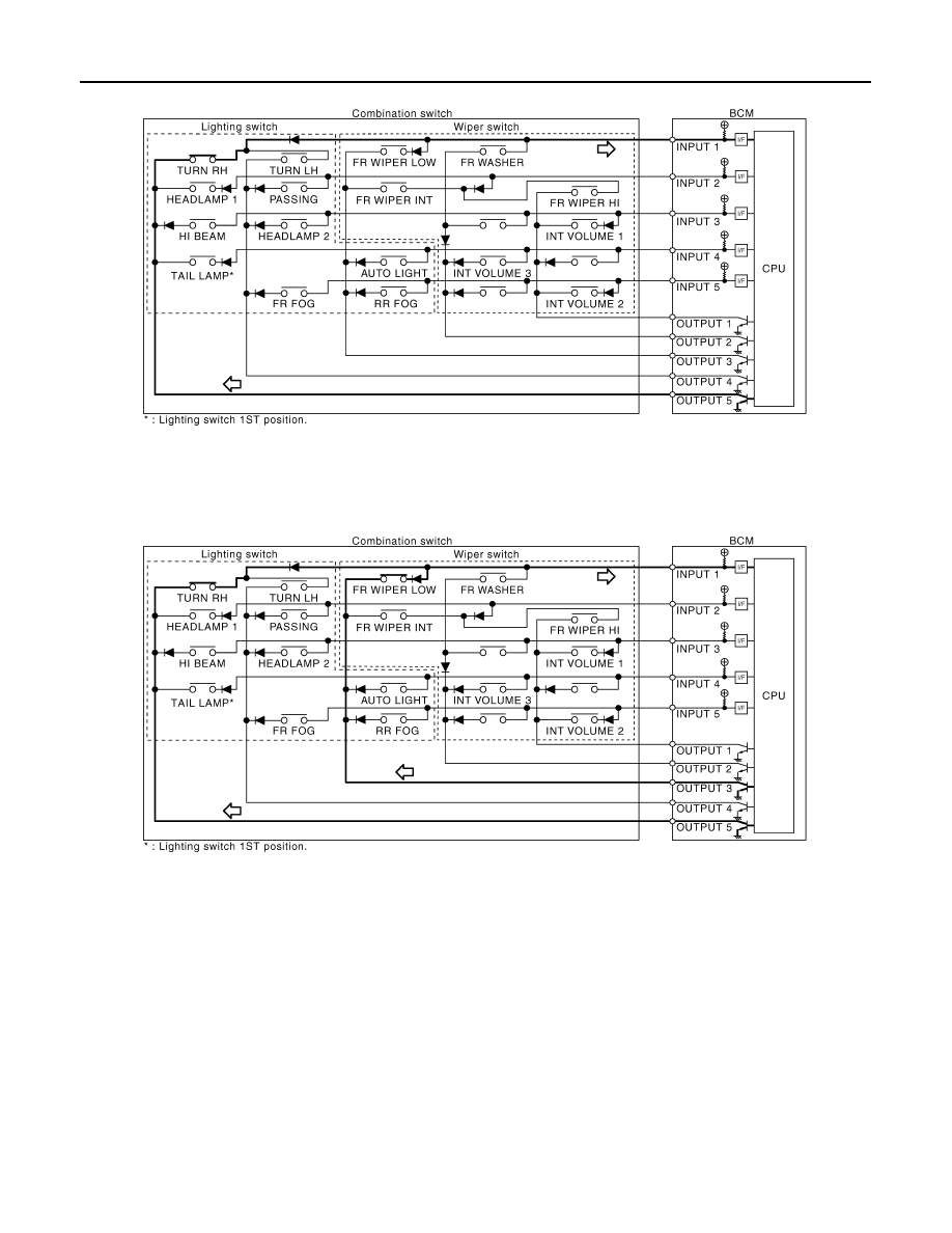
• The circuit between INPUT 1 and OUTPUT 5 is formed when the TURN RH switch is turned ON.

• BCM detects the combination switch status signal “1E” when the signal of OUTPUT 5 is input to INPUT 1.
• BCM judges that the TURN RH switch is ON when the signal “1E” is detected.

Example 2: When some switches (turn RH switch, front wiper LO switch) are turned ON

• The circuits between INPUT 1 and OUTPUT 5 and between INPUT 1 and OUTPUT 3 are formed when the

TURN RH switch and FR WIPER LOW switch are turned ON.

• BCM detects the combination switch status signal “1CE” when the signals of OUTPUT 3 and OUTPUT 5 are

input to INPUT 1.

• BCM judges that the TURN RH switch and FR WIPER LOW switch are ON when the signal “1CE” is

detected.

WIPER INTERMITTENT DIAL POSITION SETTING (FRONT WIPER INTERMITTENT OPERATION)

BCM judges the wiper intermittent dial 1 - 7 by the status of INT VOLUME 1, 2 and 3 switches.

JPMIA0736GB

JPMIA0737GB

BCS

COMBINATION SWITCH READING SYSTEM

BCS-11

< FUNCTION DIAGNOSIS >

C

D

E

F

G

H

I

J

K

L

B

A

O

P

N

Component Parts Location

INFOID:0000000003809588

Wiper intermittent

dial position

Intermittent

operation delay

interval

INT VOLUME switch ON/OFF status  

INT VOLUME 1 switch

INT VOLUME 2 switch

INT VOLUME 3 switch

1

Short

Long

ON

ON

ON

2

ON

ON

OFF

3

ON

OFF

OFF

4

OFF

OFF

OFF

5

OFF

OFF

ON

6

OFF

ON

ON

7

OFF

ON

OFF

1.

Combination switch

2.

BCM

A.

Behind of combination meter

JPMIA1041ZZ

BCS-12

< FUNCTION DIAGNOSIS >

SIGNAL BUFFER SYSTEM

SIGNAL BUFFER SYSTEM

System Diagram

INFOID:0000000003809589

System Description

INFOID:0000000003809590

OUTLINE

BCM has the signal transmission function that outputs/transmits each input/received signal to each unit.

Signal transmission function list

JPMIA1045GB

Signal name

Input

Output

Description

• Ignition switch ON signal
• Ignition switch signal

Push-button ignition switch 
(push switch)

• IPDM E/R (CAN)
• Driver seat control unit (CAN)

Inputs the push-button ignition 
switch (push switch) signal and 
transmits the ignition switch sta-
tus judged with BCM via CAN 
communication.

Door switch signal

Any door switch

• Combination meter (CAN)
• IPDM E/R (CAN)
• Driver seat control unit (CAN)
• AV control unit (CAN)

Inputs the door switch signal 
and transmits it via CAN com-
munication.

Trunk switch signal

Trunk room lamp switch

• Combination meter (CAN)
• AV control unit (CAN)

Inputs the trunk room lamp 
switch signal and transmits the 
trunk switch signal via CAN 
communication.

Oil pressure switch signal

IPDM E/R (CAN)

Combination meter (CAN)

Transmits the received oil pres-
sure switch signal via CAN 
communication.

Stop lamp switch signal

Stop lamp switch

TCM (CAN)

Inputs the stop lamp switch sig-
nal and transmits it via CAN 
communication.

BCS

POWER CONSUMPTION CONTROL SYSTEM

BCS-13

< FUNCTION DIAGNOSIS >

C

D

E

F

G

H

I

J

K

L

B

A

O

P

N

POWER CONSUMPTION CONTROL SYSTEM

System Diagram

INFOID:0000000003809591

System Description

INFOID:0000000003809592

OUTLINE

• BCM incorporates a power saving control function that reduces the power consumption according to the

vehicle status. 

• BCM switches the status (control mode) by itself with the power saving control function. It performs the sleep

request to each unit (IPDM E/R, combination meter, driver seat control unit and automatic back door control
unit) that operates with the ignition switch OFF.

Normal mode (wake-up)

- CAN communication is normally performed with other units
- Each control with BCM is operating properly

CAN communication sleep mode (CAN sleep)

- CAN transmission is stopped
- Control with BCM only is operating

Low power consumption mode (BCM sleep)

- Low power consumption control is active
- CAN transmission is stopped

LOW POWER CONSUMPTION CONTROL WITH BCM

BCM reduces the power consumption with the following operation in the low power consumption mode.
• The reading interval of the each switches changes from 10 ms interval to 60 ms interval.

Sleep mode activation

• BCM receives the sleep-ready signal (ready) from IPDM E/R and combination meter via CAN communica-

tion.

• BCM transmits the sleep wake up signal (sleep) to each unit when all of the CAN sleep conditions are ful-

filled.

• Each unit stops the transmission of CAN communication with the sleep wake up signal. BCM is in CAN com-

munication sleep mode.

• BCM is in the low power consumption mode and perform the low power consumption control when all of the

BCM sleep conditions are fulfilled with CAN sleep condition.

JPMIA1046GB


Content   ..  205  206  207  208   ..