Mitsubishi Galant. Manual - part 191


  Index      Mitsubishi     Mitsubishi Galant - service repair manual 2001 year


Search            


Content   ..  189  190  191  192   ..


Mitsubishi Galant. Manual - part 191


ON-VEHICLE SERVICE

TSB Revision

MULTIPORT FUEL INJECTION (MFI) <2.4L>

13A-445

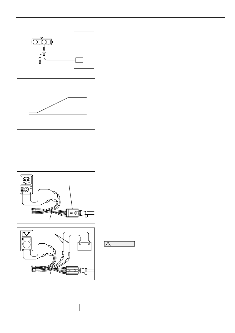
Check using oscilloscope
1. Disconnect the throttle position sensor connector and 

connect the test harness special tool (MB991348) in 
between.(All terminals should be connected.)

2. Connect the oscilloscope probe to the throttle position 

sensor side connector terminal 3.

3. Turn the ignition switch "ON" position.

4. Slowly move the throttle lever from the idle position to the 

full-throttle position and check then if the waveform is free 
from any noise.

5. If any noise is recognized, replace the throttle position 

sensor.

NOTE: After replacement, the throttle position sensor should 
be adjusted. (Refer to 

P.13A-437

.)

HEATED OXYGEN SENSOR CHECK

M1131005000099

Required Special Tools:
MB991658: Test Harness Set
MD998464: Test Harness
<Heated oxygen sensor (rear)>
1. Using scan tool MB991502, observe HO

2

S reading. If 

values are unsatisfactory, or if Scan tool is not available, use 
the following procedure:

(1) Disconnect the heated oxygen sensor connector and 

connect special tool MB991658 to the connector on the 
heated oxygen sensor side.

(2) Make sure that there is continuity [11-18 

 at 20

°

C

 (68°


F)] between terminal 3 and terminal 4 on the heated 
oxygen sensor connector

(3) If there is no continuity, replace the heated oxygen 

sensor.

(4) Warm up the engine until engine coolant is 80

°

 C (176

°

F

or higher

.

CAUTION

Be very careful when connecting the jumper wires; 
incorrect connection can damage the heated oxygen 
sensor.

(5) Use the jumper wires to connect terminal 3 of the heated 

oxygen sensor connector to the positive battery terminal 
and terminal 4 to the negative battery terminal.

(6) Connect a digital voltage meter between terminal 1  and 

terminal 2.

2. While repeatedly revving the engine, measure the heated 

oxygen sensor output voltage.

AKX01461AB

THROTTLE POSITION
SENSOR CONNECTOR

OSCILLOSCOPE

1 2 3 4

AKX01462AB

NORMAL WAVEFORM

THROTTLE LEVER
FULL-THROTTLE
POSITION

THROTTLE
LEVER
IDLE
POSITION

AK000121AB

HEATED OXYGEN SENSOR
EQUIPMENT SIDE CONNECTOR

MB991658

AK000122

JUMPER
WIRES

MB991658

AB

ON-VEHICLE SERVICE

TSB Revision

MULTIPORT FUEL INJECTION (MFI) <2.4L>

13A-446

Standard value:

3. If the sensor is defective, replace the heated oxygen sensor.

NOTE: For removal and installation of the heated oxygen 
sensor, refer to GROUP 15, Exhaust Pipe and Main Muffler 
(

P.15-18

).

<Heated oxygen sensor (front)>
1. Using the scan tool MB991502, observe HO

2

S reading. If 

values are unsatisfactory, or if Scan tool is not available, use 
the following procedure:

(1) Disconnect the heated oxygen sensor connector and 

connect special tool MD998464 to the connector on the 
heated oxygen sensor side.

(2) Make sure that there is continuity [4.5 

 8.0 

 at 20

°

(68°

F)] between terminal 1 (red clip of special tool ) and 

terminal 3 (blue clip of special tool ) on the heated oxygen 
sensor connector

(3) If there is no continuity, replace the heated oxygen 

sensor.

(4) Warm up the engine until engine coolant is 80

°

C (176

°

F) 

or higher.

CAUTION

Be very careful when connecting the jumper wires; 
incorrect connection can damage the heated oxygen 
sensor.

(5) Use the jumper wires to connect terminal 1 (red clip) of 

the heated oxygen sensor connector to the positive 
battery terminal and terminal 3 (blue clip) to the negative 
battery terminal.

(6) Connect a digital voltage meter between terminal 2 (black 

clip) and terminal 4 (white clip).

2. While repeatedly revving the engine, measure the heated 

oxygen sensor output voltage.

Standard value:

ENGINE

HEATED OXYGEN 
SENSOR OUTPUT 
VOLTAGE

REMARKS

When revving 
engine

0.6 

 1.0V

If you make the air/
fuel ratio rich by 
revving the engine 
repeatedly, a 
normal heated 
oxygen sensor will 
output a voltage of 
0.6 

 1.0V.

AKX01624

HEATED
OXYGEN
SENSOR
EQUIPMENT
SIDE
CONNECTOR

MD998464

BLUE

RED

AC

AKX01625AC

BLUE

RED

BLACK

JUMPER
WIRES

WHITE

MD998464

ON-VEHICLE SERVICE

TSB Revision

MULTIPORT FUEL INJECTION (MFI) <2.4L>

13A-447

3. If the sensor is defective, replace the heated oxygen sensor.

NOTE: For removal and installation of the heated oxygen 
sensor, refer to GROUP 15, Exhaust Pipe and Main Muffler 
(

P.15-18

).

INJECTOR CHECK

M1131005200082

Measurement of Resistance between Terminals

1. Disconnect the injector intermediate connector.

2. Measure resistance between terminals.

Standard value: 13 

−−−−

 16 

 [at 20

°°°°

C (68

°°°°

F)]

3. If not within specification, replace the injector.

4. Install the injector connector

Checking operation sound

Using a stethoscope or long blade screwdriver, check the 
operation sound ("tick-tick-tick") of injectors during idling or 
during cranking. Check that as the engine speed increases, the 
frequency of the operating sound also increases.
1. If the injector you are checking is not operating, you may 

hear the operating sound of the other injectors.

2. If no operating sound is heard from the injector that is being 

checked, check the injector drive circuit. If there is nothing 
wrong with the circuit, a defective injector or powertrain 
control module (PCM) is suspected.

IDLE AIR CONTROL MOTOR (STEPPER MOTOR) 
CHECK

M1131005400105

Required Special Tool:
MB991709: Test Harness Set

ENGINE

HEATED OXYGEN 
SENSOR OUTPUT 
VOLTAGE

REMARKS

When revving 
engine

0.6 

 1.0V

If you make the air/
fuel ratio rich by 
revving the engine 
repeatedly, a 
normal heated 
oxygen sensor will 
output a voltage of 
0.6 

 1.0V.

AK000602AB

1 2

AK000124 AB

STETHOSCOPE

ON-VEHICLE SERVICE

TSB Revision

MULTIPORT FUEL INJECTION (MFI) <2.4L>

13A-448

Checking the Operation Sound
1. Check that the engine coolant temperature is 20

°

C (68

°

F

ορ βελοω.

NOTE: If necessary, you can disconnect the engine coolant 
temperature sensor connector and connect the harness-side 
of the connector to another engine coolant temperature 
sensor that is at 20

°

C (68

°

F) or below

.

2. Check that the operation sound of the stepper motor can be 

heard after the ignition is switched ON (but without starting 
the motor).

3. If the operation sound cannot be heard, check the stepper 

motor's activation circuit. If the circuit is normal, it is 
probable that there is a malfunction of the stepper motor or 
powertrain control module (PCM).

Checking the Coil Resistance
1. Disconnect the idle air control motor connector.

2. Measure resistance between terminal 2 and either terminal 

1 or terminal 3 of the connector at the idle air control motor 
side.

Standard value: 28 

−−−−

 33 

 [at 20

°°°°

C


(68

°°°°

F)]

3. If resistance is not within the standard value, replace the IAC 

motor.

4. Measure the resistance between terminal 5 and either 

terminal 6 or terminal 4 of the connector at the idle air 
control motor side.

Standard value: 28 

−−−−

 33 

 [at 20

°°°°

C (68

°°°°

F)]

5. If resistance is not within the standard value, replace the IAC 

motor.

<Operation Check>

1. Remove the throttle body.

2. Remove the idle air control motor.

3. Connect special tool MB991709 to the idle air control motor 

connector.

4. Connect the positive (+) terminal of a power supply 

(approximately 6 V) to terminal 2 and the terminal 5. 

5. Connect the negative (-) terminal of the power supply to 

each clip as described in the following steps. Then check 
whether or not the stepper motor vibrates slighly as it 
operates.

(1) Connect the negative terminal of the power supply to 

terminal 1 and terminal 4.

(2) Connect the negative terminal of the power supply to 

terminal 3 and terminal 4.

AKX01561

1 2 3
4 5 6

1 2 3
4 5 6

AB

AKX01627AB

TERMINAL 2

IAC MOTOR

TERMINAL 5

MB991709


Content   ..  189  190  191  192   ..