Mitsubishi Galant. Manual - part 192
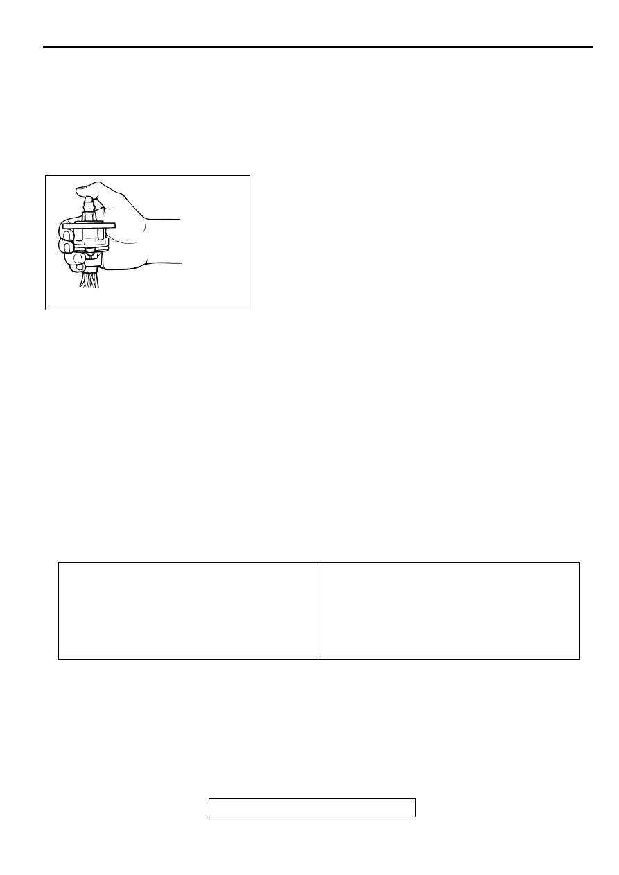
INJECTOR
TSB Revision
MULTIPORT FUEL INJECTION (MFI) <2.4L>
13A-449
(3) Connect the negative terminal of the power supply to
terminal 3 and terminal 6.
(4) Connect the negative terminal of the power supply to
terminal 1 and terminal 6.
(5) Connect the negative terminal of the power supply to
terminal 1 and terminal 4.
(6) Repeat the tests in sequence from (5) to (1) to test
opposite movement of the IAC.
6. If vibration is detected during the test, the stepper motor can
be considered to be normal.
EVAPORATIVE EMISSION PURGE SOLENOID
CHECK
M1131005600079
Refer to GROUP 17, Emission Control System
−
Evaporative
Emission Control System
−
Evaporative Emission Purge
Solenoid Check (
EGR SOLENOID CHECK
M1131005700076
Refer to GROUP 17, Emission Control System
−
Exhaust Gas
Recirculation (EGR) System - EGR Solenoid Check (
IN JEC TO R
REMOVAL AND INSTALLATION
M1131007100081
AKX01626
Pre-removal Operation
•
Fuel Discharge Prevention (Refer to
•
Engine Coolant Draining [Refer to GROUP 00,
Maintenance Service
−
Engine Coolant (Change)
•
Air Cleaner Removal (Refer to GROUP 15, Air
Cleaner
•
Throttle Body Removal (Refer to
Post-installation Operation
•
Throttle Body Installation (Refer to
•
Air Cleaner Installation (Refer to GROUP 15, Air
Cleaner
.)
•
Engine Coolant Refilling [Refer to GROUP 00,
Maintenance Service
−
Engine Coolant (Change)
.]
•
Fuel Leakage Inspection