Mazda 6. Manual - part 385


  Index      Mazda     Mazda 6 - service repair manual 2002 year


Search            


Content   ..  383  384  385  386   ..


Mazda 6. Manual - part 385


U–44

CONTROL SYSTEM 

End Of Sie

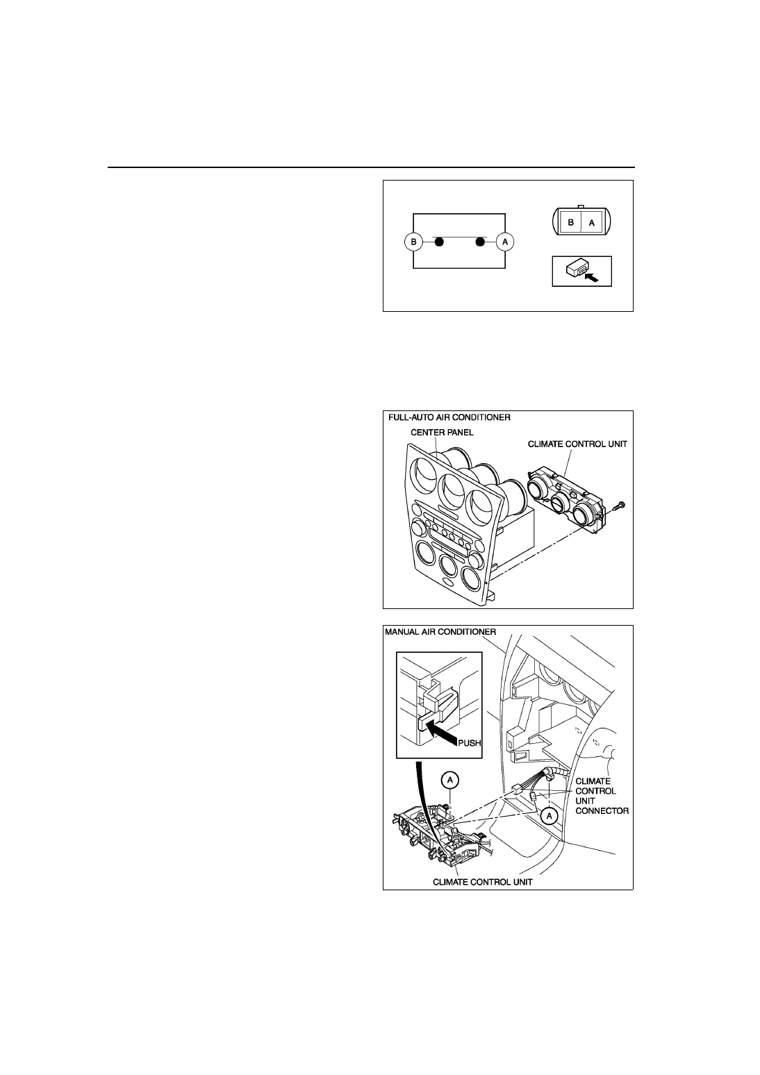
CLIMATE CONTROL UNIT REMOVAL

A6E854061190W03

1. Disconnect the negative battery cable.
2. Disconnect the air mix and airflow mode wires from each wire clamp and link. (Manual air conditioner)
3. Remove the center panel. (See 

T–96 CENTER PANEL MODULE REMOVAL/INSTALLATION

.)

4. Remove the screws and climate control unit. (Full-auto air conditioner)
5. Release the hook and pull the climate control unit toward you. (Manual air conditioner)
6. Disconnect the climate control unit connectors 

and remove the climate control unit. (Manual air 
conditioner)

End Of Sie

A6E8540W027

A6E8540W028

A6E8540W059

CONTROL SYSTEM 

U–45

U

CLIMATE CONTROL UNIT INSTALLATION

A6E854061190W04

1. Pass each wire through the following routes then 

connect to A/C unit. (Manual air conditioner)

2. Connect the climate control unit connectors. 

(Manual air conditioner)

3. Install the climate control unit to the center panel. 

(Full-auto air conditioner)

4. Install the center panel.
5. Adjust the climate control unit wires. (Manual air 

conditioner) (See 

U–46 CLIMATE CONTROL 

UNIT WIRE ADJUSTMENT

.)

6. Connect the negative battery cable.

End Of Sie

CLIMATE CONTROL UNIT DISASSEMBLY/ASSEMBLY

A6E854061190W01

1. Disassemble in the order indicated in the table.

2. Assemble in the reverse order of disassembly.

A6E8540W029

1

Illumination bulb

2

Body

1

Fan switch

2

Air mix wire
(See 

U–46 Wire Disassembly Note

)

(See 

U–46 Wire Assembly Note

)

3

Airflow mode wire
(See 

U–46 Wire Disassembly Note

)

(See 

U–46 Wire Assembly Note

)

4

Body

A6E8540W061

A6E8540W030

U–46

CONTROL SYSTEM 

Wire Disassembly Note

1. Disassemble the wires in the shown in the figure.

Wire Assembly Note

1. Assemble the wires to the position as shown in 

the figure.

End Of Sie

CLIMATE CONTROL UNIT WIRE ADJUSTMENT

A6E854061190W05

Air Mix Wire

1. Set the temperature control dial at max cold.
2. Set the air mix link to max cold in the direction shown 

by the arrow and insert a screwdriver at the set hole.

3. Connect the air mix wire to air mix link.
4. Clamp the air mix wire to wire clamp.
5. Verify that the temperature control dial moves its full 

stroke.

Airflow Mode Wire

1. Set the airflow mode control dial at defroster.

A6E8540W031

A6E8540W032

A6E8540W033

A6E8540W034

CONTROL SYSTEM 

U–47

U

2. Set the airflow mode main link to defroster in the 

direction shown by the arrow and insert a 
screwdriver at the set hole.

3. Connect the airflow mode wire to airflow mode 

main link.

4. Clamp the airflow mode wire to wire clamp.
5. Verify that the airflow mode control dial moves its 

full stroke.

End Of Sie

CLIMATE CONTROL UNIT INSPECTION

A6E854061190W02

Full-auto Air Conditioner

1. Connect the all center panel connectors.
2. Turn the ignition switch to ON position.
3. Measure the voltage at each climate control unit terminal and refer to the terminal voltage list.

• If not as specified, inspect the parts listed under “Action” and the related wiring harness.

— If there is any malfunction, replace the climate control unit.

Terminal Voltage List (Reference)

A6E8540W035

Terminal

Signal

Connected to 

Test condition

Voltage (V)

Action

1A

Blower motor 
feedback signal

• Blower motor

• Power MOS 

FET

Fan switch is OFF

12

1. Inspect for continuity or 

short circuit (Climate control 
unit—blower motor: 1A—B) 
(Climate control unit—power 
MOS FET: 1A—B, 1C—E) 
(Blower motor—blower 
relay: A—C) (Blower relay—
fuse: D—BLOWER 40 A 
fuse)

2. Inspect for continuity (Power 

MOS FET—ground: A—
GND) (Blower relay—
ground: A—GND)

3. Inspect power MOS FET
4. Inspect blower motor
5. Inspect blower relay
6. Inspect BLOWER 40 A fuse
7. Replace power MOS FET

Fan switch is at manual 
LO

7.8

Fan switch is at manual 
HI

0.2

1B

+5 V

• Air mix actuator

• Airflow mode 

actuator

• Solar radiation 

sensor

Ignition switch at ON 
position

5.0

• Inspect for short circuit 

(Climate control unit— air 
mix actuator, airflow mode 
actuator, solar radiation 
sensor: 1B—B, B, A)

• Inspect air mix actuator

• Inspect airflow mode 

actuator

• Inspect solar radiation 

sensor

• Inspect terminal voltage of 

climate control unit 
connector (2H, 2L)

Ignition switch at LOCK 
position

Below 1.0

• Replace climate control unit

A6E8540W038


Content   ..  383  384  385  386   ..