Mazda 6. Manual - part 257
P–84
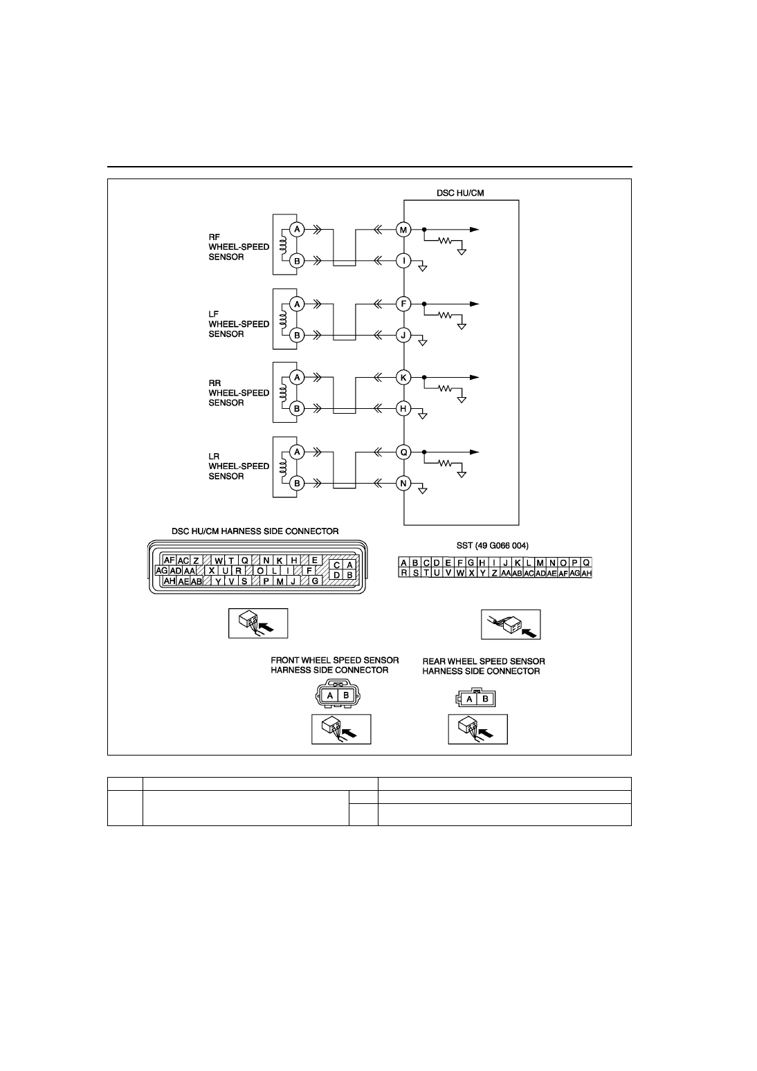
ON-BOARD DIAGNOSTIC (DYNAMIC STABILITY CONTROL)
Diagnostic procedure
STEP
INSPECTION
ACTION
1
VERIFY OTHER DTC HAS BEEN RECORDED
• Have DTCs related to solenoid valve, pump
motor, or pump motor relay been stored?
Yes
Go to applicable DTC inspection.
No
Go to next step.