Mazda 6. Manual - part 204
ON-BOARD DIAGNOSTIC
K–57
K
End Of Sie
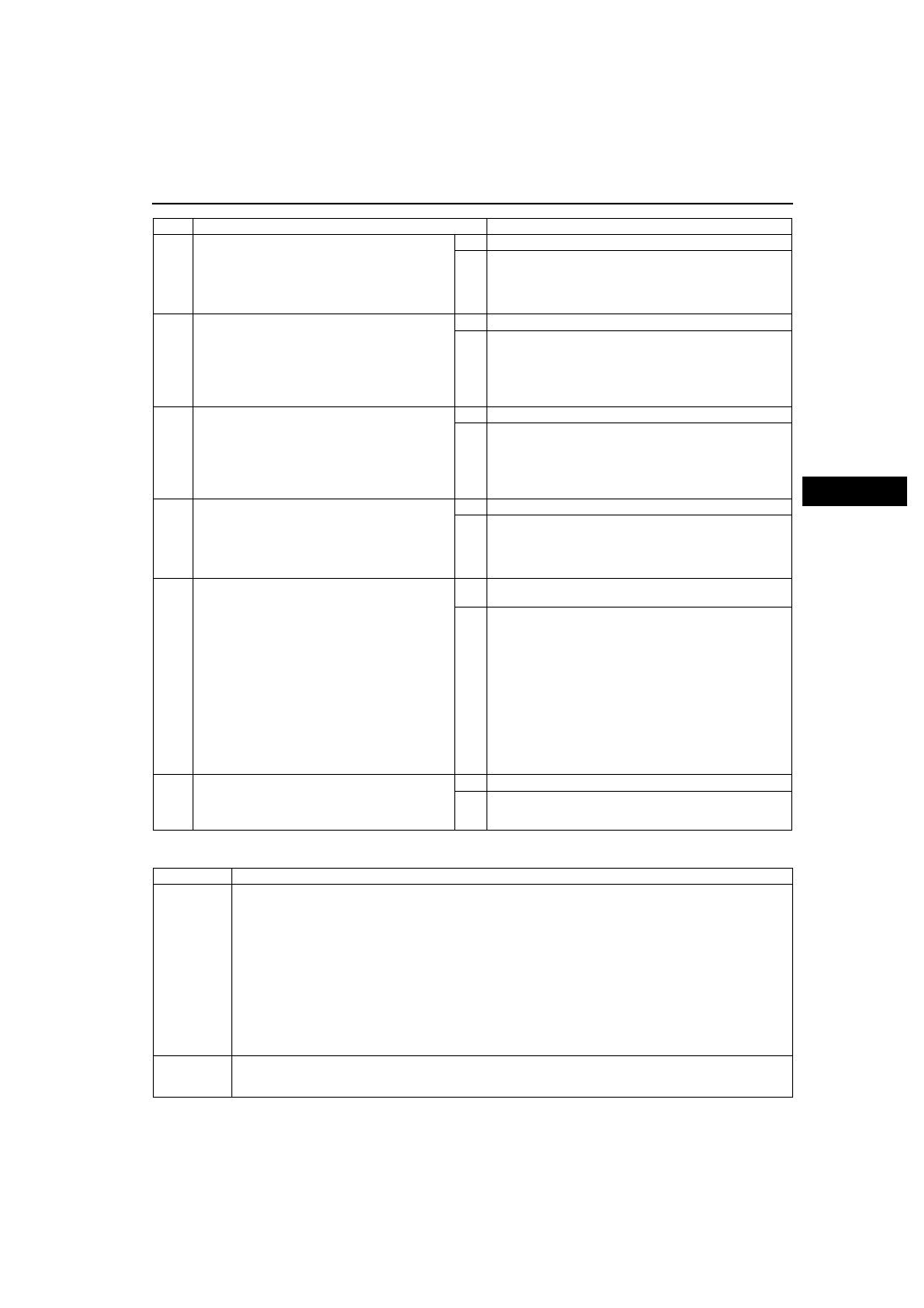
DTC P0706
A6E567001030W06
6
INSPECT PCM CONNECTOR FOR POOR
CONNECTION
• Disconnect PCM connector.
• Check for poor connection (damaged/pulled-
out terminals, corrosion, etc.).
• Is connection okay?
Yes Go to next step.
No
Repair or replace pin or connector, then go to Step 10.
7
INSPECT VEHICLE SPEED SIGNAL CIRCUIT
FOR OPEN
• Disconnect PCM connector and VSS
connector.
• Inspect for continuity between VSS terminal B
and PCM terminal 3C.
• Is there continuity?
Yes Go to next step.
No
Repair or replace harness, then go to Step 10.
8
INSPECT VEHICLE SPEED SIGNAL CIRCUIT
FOR SHORT TO GROUND
• Verity that VSS connector and PCM connector
are disconnected.
• Inspect for continuity between PCM terminal
3C and body ground.
• Is there continuity?
Yes Repair or replace harness, then go to Step 10.
No
Repair VSS, then go to Step 14.
9
INSPECT PCM CONNECTOR FOR POOR
CONNECTION
• Disconnect PCM connector.
• Check for poor connection (damaged/pulled-
out terminals, corrosion, etc.).
• Is connection okay?
Yes Go to next step.
No
Repair or replace pin or connector, then go to Step 10.
10
VERIFY TROUBLESHOOTING OF DTC P0500
COMPLETED
• Make sure to reconnect all disconnected
connectors.
• Clear DTC from memory using WDS or
equivalent.
• Warm up engine.
• Drive vehicle under following conditions for 4.5
seconds or more while monitoring PIDs.
— Engine coolant temp: 60
°C {140 °F} or
above
— Drive in L range
— Frequency of input/turbine speed sensor:
800 Hz or above
• Is pending code present?
Yes Replace PCM, then go to next step.
(See
No
No concern is detected. Go to next step.
11
VERIFY AFTER REPAIR PROCEDURE
• Perform “After Repair Procedure”.
• Are any DTCs present?
Yes Go to applicable DTC inspection.
No
Troubleshooting completed.
STEP
INSPECTION
ACTION
DTC P0706
Transaxle range (TR) switch range/performance
DETECTION
CONDITION
• When all conditions below are satisfied and 100 seconds or more have passed.
— Engine speed 530 rpm or above.
— Vehicle speed 20 km/h {12 mph} or above.
— voltage at PCM terminal 1W is 0.5 V or above.
— P, R, N, D, S or L range/position not detected.
Diagnostic support note:
• This is a continuous monitor (CCM).
• MIL illuminates if PCM detects the above malfunction condition in two consecutive drive cycles or in one
drive cycle while the DTC for the same malfunction has been stored in the PCM.
• PENDING CODE is available if PCM detects the above malfunction condition during first drive cycle.
• FREEZE FRAME DATA is available.
• HOLD indicator light flashes.
• DTC is stored in the PCM memory.
POSSIBLE
CAUSE
• TR switch malfunction
• TR switch misadjustment
• PCM malfunction